


Abstract
Statistical dependences among features of coronal mass ejections (CMEs), solar flares, and sigmoidal structures in soft-X-ray images were investigated. We applied analysis methods to all the features in the same way in order to investigate the reproducibility of the correlations among them, which may be found from previous statistical studies. Samples of 211 M-class and X-class flares, observed between 2006 and 2015 by the Hinode/X-ray telescope, Solar and Heliospheric Observatory/Large Angle and Spectrometric Coronagraph, and Geostationary Operational Environmental Satellite, were examined statistically. Five kinds of analysis were performed: occurrence rate analysis, linear-correlation analysis, association analysis, the Kolmogorov–Smirnov test, and the Anderson–Darling test. These give three main results. First, the sigmoidal structure and long-duration events (LDEs) have a stronger dependence on CME occurrence than large X-ray-class events in on-disk events. Second, for the limb events, a significant dependence exists between LDEs and CME occurrence, and between X-ray-class events and CME occurrence. Third, 32.4% of on-disk flare events have sigmoidal structure and are not accompanied by CMEs. However, the occurrence probability of CMEs without sigmoidal structure is very small, 8.8%, in on-disk events. While the first and second results are consistent with previous studies, we provide for the first time a difference between the on-disk and limb events. The third result, that non-sigmoidal regions produce fewer eruptive events, is also different from previous results. We suggest that sigmoidal structures in soft X-ray images will be a helpful feature for CME prediction in on-disk flare events.
1. Introduction
Coronal mass ejections (CMEs) are large amounts of plasma ejected from the solar corona into interplanetary space, thereby having a great influence on the space environment. CMEs sometimes disturb the magnetosphere of the Earth, leading to catastrophic consequences for satellites and communication systems (Clark 2006). Other explosive events, known as solar flares, also occur in the solar atmosphere. These are defined as an abrupt increase in electromagnetic radiation with a broad spectral range.
The relation between CMEs and solar flares is an important topic in solar physics. First, CMEs were considered to be initiated by large flares (Lin & Hudson 1976). However, Zhang et al. (2001) showed that CMEs are initiated before the onset of the associated flares. In their investigation, four CME events were analyzed with the Large Angle and Spectrometric Coronagraph (LASCO; Brueckner et al. 1995) and Extreme-ultraviolet Imaging Telescope (EIT; Delaboudinière et al. 1995) aboard the Solar and Heliospheric Observatory (SOHO; Domingo et al. 1995). Scenarios in which CMEs are driven by flare-induced thermal pressure were rejected. Although there seems to be a close relation between CMEs and solar flares, not all solar flares are accompanied by CMEs. Bein et al. (2012) reported that 25% of CMEs were not associated with solar flares. It is also known that solar flares without CMEs exist (Yashiro et al. 2006). Solar flares are roughly classified into two types: eruptive flares (with CMEs) and confined flares (without CMEs). In eruptive flares, the eruption of a magnetic flux rope corresponds to a CME and the heated plasma caused by the magnetic reconnection is observed as a solar flare (see the review by Shibata & Magara 2011). Gas motion in the lower atmosphere, e.g., shear, rotation, and emergence, are thought to contribute to the storage of magnetic energy in the corona (Krall et al. 1982; Hagyard et al. 1984; Leka et al. 1996) and to lead to solar flares and/or CMEs through certain initiation processes, e.g., breakout (Antiochos et al. 1999), tether cutting (Moore et al. 2001), preflare reconnection (Kusano et al. 2012; Bamba et al. 2013; Wang et al. 2017), or magnetohydrodynamic instabilities (Kruskal & Schwarzschild 1954; Kliem & Török 2006; Ishiguro & Kusano 2017). Although these models can explain specific flare–CME events, the question of which kind of solar flare (or coronal magnetic field configuration) is strongly related to the presence/absence of CMEs, is inconclusive from the statistical viewpoint.
Since coronal plasmas are heated to 10–20 MK during solar flares, the characteristics of solar flares are often identified through X-ray observations (e.g., Benz 2017 and references therein). The magnitude of a solar flare is usually defined by the peak flux of the soft-X-ray measured by the Geostationary Operational Environmental Satellite (GOES) and classified into several classes (A, B, C, M, and X). The light curves in soft X-rays are also characteristic features in solar flares, and can be divided into two phases: a rise and decay phase. The duration of solar flares ranges from several minutes to a few hours. Since the decay time corresponds to the plasma cooling time due to radiation and thermal conduction, the decay time is often used to diagnose the size of flaring loops (Reale 2002).
Several statistical observational studies have been done to investigate the properties of solar flares and/or CMEs. By focusing on flare occurrence, Bobra & Couvidat (2015) showed that a few parameters (total unsigned current helicity, total magnitude of Lorentz force, and total photospheric magnetic free energy density) are more relevant to the occurrence of solar flares than other parameters (mean photospheric magnetic free energy and mean current helicity). Zhang & Liu (2015) indicated that the rise time of the soft-X-ray flux of a flare is approximately half of the decay time, and the rise and decay times increase with variations in the peak flux of the soft X-ray. Regarding CMEs, Yashiro et al. (2006) investigated the frequency distributions in the energy of solar flares and found that the power law indices of the frequency distributions for flares without CMEs are steeper than those for flares with CMEs. According to Toriumi et al. (2017), if the area of flare ribbons normalized by the sunspot area is large, solar flares tend to be accompanied by CMEs.
Another important observational characteristic of solar flares is the shape of the magnetic field lines in the corona. Since the plasmas in the corona are frozen to the magnetic field lines, the loop-like structure, which can be seen through soft X-ray or extreme ultraviolet (EUV) observations, reflects the structure of the magnetic field lines. One of the characteristic coronal structures in flare-productive active regions is a sigmoid—an S-shaped or inverse S-shaped bright structure visible in soft X-ray and EUV high-temperature line images (Rust & Kumar 1996; Liu et al. 2007; Cheng et al. 2014). A sigmoidal structure is thought to be formed by flux emergence (Archontis et al. 2009) or flux cancellation (van Ballegooijen & Martens 1989; Savcheva et al. 2012). Since sigmoids are bundles of twisted magnetic field lines containing electric currents and thus free energy, sigmoids are likely to be eruptive (Canfield et al. 1999). Savcheva et al. (2014) reported that 64% of sigmoids produce flares and Hα filaments are observed in 65% of sigmoids in the analysis of a sample of 72. Conventionally, sigmoids are identified by visual inspection, including the study of Savcheva et al. (2014). However, with increasing sample number, the identification of sigmoids requires more time and effort. In this study, we develop a new method for detecting the shape of bright X-ray regions and supporting the identification of sigmoids.
Some studies have focused on comparisons between CMEs and solar flares. Dumbović et al. (2015) aimed to investigate the relation between the geomagnetic disturbance storm time (Dst: the temporal variation of the Earth's magnetic field, which contains information on the ring current around Earth), CME parameters, and solar flare parameters. Their results confirmed that the initial CME speeds, apparent width, position, and class of solar flare are related to the magnitude of geomagnetic storms. Tiwari et al. (2015) also studied the relation between CME speeds and magnetic parameters such as magnetic flux, magnetic twist, and free magnetic energy proxies. They showed that global alpha parameter (Tiwari et al. 2009) determines the CME speed upper limit. Few studies have focused in detail on the statistical relation between the existence of sigmoids and the occurrence of CMEs, although Canfield et al. (1999) investigated the eruptivity of sigmoids using only soft-X-ray data with Yohkoh (Tsuneta et al. 1991). In this study, we focus on the relations between coronal parameters, e.g., X-ray class, duration of solar flares, and existence of sigmoids and CME parameters, e.g., existence, speed, and size. We applied data obtained by the Hinode satellite (Kosugi et al. 2007), SOHO, and GOES. These missions have been observing the Sun for more than ten years and enable statistical studies with enormous and uniform data quantities. Although previous statistical studies have investigated relations between CMEs, solar flares, and sigmoidal structures, none investigated all of the relations between them in the same manner. Thus, the purpose of this investigation is to confirm the statistical relations between all of the features or parameters by applying common analysis methods to the data set.
This paper is organized as follows. The observations and data selection are described in Section 2, and the analysis is explained in Section 3. Section 4 presents the results, followed by a discussion in Section 5.
2. Data Selection and Observations
Events were selected based on flare observations. We used the Hinode flare catalog (Watanabe et al. 2012), which describes whether each solar flare was observed by the Hinode instruments. A set of 211 flare events was selected from the period between 2006 December and 2015 June based on the following criteria:
- (i)larger than M-class flares (according to the soft-X-ray flux peak measured with GOES);
- (ii)existence of at least one map observed with the spectropolarimeter (Lites et al. 2013), which is one of two focal-plane instruments of the Solar Optical Telescope (Ichimoto et al. 2008; Shimizu et al. 2008; Suematsu et al. 2008; Tsuneta et al. 2008) aboard the Hinode satellite, within 6 hr before and after the flare peak.
The first criterion was set in order to focus on the relation between large flares, CMEs, and sigmoids. The second criterion aims to investigate quantitatively the properties of the photospheric magnetic field in relation to the occurrence of flares and CMEs in our subsequent studies.
To identify sigmoidal structures, we analyzed soft-X-ray images observed with the X-ray telescope (XRT: Golub et al. 2007; Kano et al. 2008) aboard the Hinode satellite. Recent observations show that sigmoids can be identified not only through soft X-ray but also through EUV observations (Liu et al. 2007), which means that sigmoids have a wide range of temperature (1–10 MK). However, the sigmoidal structure is most prominent and easily identified in soft-X rays (Savcheva et al. 2014), which we use in this study. The XRT can observe coronal plasmas in a wide temperature range using several filters. The majority of the chosen flare events were observed with the Be-thin, Ti-poly, and Al-thick filters. Since the temperature sensitivity of Al-thick is extremely high, approximately 10 MK, the sigmoidal structure looks blurred. The Ti-poly filter is often saturated in the flaring region of the chosen events. Thus, images with Be-thin were used in our study. Each map consists of 384 × 384 pixels or 512 × 512 pixels at a plate scale of 1 0286 per pixel. The time cadence of the observations is different at each event (1–5 min).
To derive the duration of flares, we used time series of the 1–8 Å soft-X-ray flux observed by GOES, which obtained data at 2 s or 3 s intervals (GOES 13–15 or GOES 11–12, respectively) and provided us with a continuous soft-X-ray flux during solar flares.
3. Analysis
3.1. Property Definition of Events
The focus of our analysis is to determine the statistical relations among physical parameters of CMEs and solar flares simultaneously. We chose CME presence/absence, speed, and size as the CME parameters, and X-ray class, duration, and sigmoid presence/absence as solar lare parameters. Each characteristic is defined below.
3.1.1. CMEs
To obtain the existence and physical parameters of CMEs, we used the SOHO/LASCO catalog6 (Yashiro et al. 2004; Gopalswamy et al. 2009). In the catalog, the existence of CMEs is manually identified from LASCO C2 and C3 data, which cover the outer corona for 2.5–6.0 solar radii (C2) and 3.7–30 solar radii (C3). CME speed is defined by fitting a straight line (i.e., linear or first-order polynomial fit) to the height–time measurements, and CME width is measured in LASCO C2 after it becomes stable.
3.1.2. Duration of Flare Events
We define the flare rise time (trise), decay time (tdec), and duration (tdur) as follows:


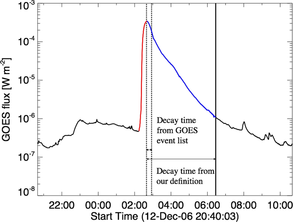
where Tst, Tpeak, and Ten are the flare start time, flare peak time, and flare end time, respectively. Although Tst, Tpeak, and Ten are provided by the GOES event list,7 we re-determined them based on the method of Aschwanden & Freeland (2012), which enabled us to distinguish more clearly between long-duration events (LDEs) and impulsive flares. In the GOES event list, the flare end time is defined as time when the flux level decays to a point halfway between the maximum flux and pre-flare background level. However, this study defines the flare end time as the time when the flux level reaches approximately the pre-flare background level. The procedure is as follows.
- 1.Data rebinning. The original time resolution of dt = 2 s or 3 s was rebinned to time steps of Δt = 6 s.
- 2.Data smoothing. The rebinned light curve was smoothed with a boxcar average, and the width of the smoothing window measured 60 s.
- 3.Detection of flare peak time. We defined the peak time, Tpeak, as the local maximum, where the X-ray flux, F(T), satisfies F(Tpeak − Δt) < F(Tpeak), F(Tpeak+Δt) < F(Tpeak), and F(Tpeak) > 10−5 W m−2.
- 4.Detection of flare start time. The definition of the flare start time (Tst) is equal to that of the GOES start time, which is determined by the first minute of a sequence of 4 min of steep monotonic increase.
- 5.Detection of flare end time. We defined the flare end time (Tend) as the time when the soft-X-ray flux satisfies F < 3Fback, with Fback as the background flux, which is defined by the average X-ray flux 36 s before the flare start time.
Figure 1 shows an example of GOES X-class flares and our detection of the rise time (red line), decay time (blue line), and duration (red line + blue line) described above. The peak and end times from the GOES event list are represented by the vertical dotted line. The decay time of the GOES event list is quite short (∼16 min), despite visual inspection that conventionally declared this event as an LDE. In contrast, our method captured a long decay time (∼4 hr).

Figure 1. Soft-X-ray flux observed with GOES during the period between 20:40 UT on 2006 December 12 and 10:40 UT on 2006 December 13. The red and blue lines show the rise and decays time from the definitions, respectively. The peak and end times from the GOES event list are represented by a vertical dotted line. The background flux in this event is 3 × 10⁻⁷ W m−2.
Download figure:
Standard image High-resolution imageIt should be noted that there are 20 events which occurred at decay times of other events. Further, five events lacked data and were thus excluded from our duration analysis.
3.1.3. Sigmoids
The sigmoids can be identified as S-shaped or inverse S-shaped structures with higher intensity than the surrounding structures in soft X-ray. We identified sigmoidal structures in soft-X-ray images as follows.8
First, we determined the frequency distribution of the X-ray intensity in each image to obtain the XRT noise level. The XRT data were normalized using the exposure time. The left panels in Figure 2 show examples of the frequency distribution at this step. A peak exists in the range below 50 DN s–1, which corresponds to photon noise. We determined this value by fitting the distribution with a Gaussian function for each image. The typical value of noise is 15 DN s–1. Note that the system gain of the XRT is 57 e−1/DN.

Figure 2. Examples of sigmoid structures in X-ray images. The left column shows the frequency distribution of the X-ray intensity. The asterisks were fitted with a Gaussian function and indicate the photon noise. The vertical dashed lines correspond to signals presenting the enhancement onset. The middle column shows the derivative of the frequency distribution of the X-ray intensity. The horizontal line corresponds to zero and the vertical lines correspond to the lowest signals of each enhancement range. The right column presents the results of the bright-region detection. The background represents the X-ray intensity image and the contours show discriminated bright regions. The contour colors correspond to those in the left and middle columns.
Download figure:
Standard image High-resolution imageNext, we looked for enhancement in the frequency distribution. While the distribution typically decreases as a power-law function in the range above the photon noise level, certain enhancement ranges are occasionally seen. We extracted all enhancements in the range above 100 DN s–1, which is marked with triangles in the left column of Figure 2, as ranges where the first derivative of the frequency distribution is larger than zero. The middle column of Figure 2 shows examples of this step. The horizontal line corresponds to zero and the vertical dashed lines correspond to the lowest values of enhancement ranges detected in the analysis. Afterwards, the bright enhancement region (candidate for sigmoid detection) was drawn in an X-ray intensity image using the threshold value obtained in the analysis above. The right column of Figure 2 presents an example of enhancement regions found with this method. The colors of the contour lines correspond to those of the vertical dashed ones in the left and right columns.
At the final step of sigmoid recognition, we judged whether the bright regions are S- or J-shaped. Three authors, i.e., Y. Kawabata, Y. Iida, and T. Doi, separately carried out this step by visual inspection for all bright regions of all flare events. When two or three individuals judged that the bright region had an S- or a J-shaped structure, it was classified as a sigmoid. The flare event was judged to be accompanied by a sigmoid structure when it appeared at least in one image taken in 12 hr before the flare peak time.
3.2. Association between Flare Parameters, Sigmoid Existence, and CME Occurrence
We investigated the independence of four parameters through contingency tables and probabilities of intersection sets: X-ray class, duration, sigmoid (hereafter SGM) existence, and CME existence. We define large X-ray-class (hereafter LXC) events as events in which the X-ray class is more than M2.3. LDEs are defined as events in which the duration exceeds 1 hr. Both thresholds were approximately set to the median value of the 211 and 186 events, respectively.
First, we computed the occurrence probability of each event. Events without Be-thin data were excluded from the SGM analysis. Further, CME data were excluded when it was difficult to judge whether CMEs had occurred or not. An error was obtained as a Poisson noise value in the case of many events, i.e., , with N as event number.

Next, a contingency table of the pairs among all four parameters, e.g., LXC, LDE, SGM, and CME, was created to investigate the association of each pair of parameters. We calculated the ϕ coefficient defined by

where χ is Pearson's chi-square and N is the number of events.
The association was also investigated from a different point of view. We focused on how large differences exist between the actual occurrence probabilities of the intersection sets and those assuming the independence of each parameter. We computed the occurrence probability of each intersection set, A ∩ B, from the individual occurrence probabilities by assuming independence. The occurrence probability of the intersection set could be obtained as a product due to the independent events in this case. The error bars of the intersection events, σind, were calculated as Poisson noise for each occurrence probability. The occurrence probability of the actual intersection event was obtained from the observation result. The error value, σobs, was calculated as Poisson noise from the occurrence number of the actual intersection event. Finally, we compared the occurrence probability of the intersection events with independent events with that from the actual observation obtained in the analysis above, calculated by how many multiples of the error value they were separated.
3.3. Kolmogorov–Smirnov and Anderson–Darling Tests
In order to estimate how much SGM and CME occurrence depends on the four flare properties, i.e., (i) flare duration, (ii) rise time, (iii) decay time, and (iv) soft-X-ray flux, we conducted the Kolmogorov–Smirnov (KS) test and Anderson–Darling (AD) test for each condition. The KS and AD tests judge whether two distributions are similar or not. We derived the cumulative distribution functions (CDFs) of the four parameters (i)–(iv),

where F and f are CDF and frequency distribution. Both x and t are taken from parameters (i)–(iv). The KS and AD tests were conducted for the two CDFs with and without CMEs (or SGMs). The KS and AD statistics, DKS and DAD are calculated as


where sup is the supremum, m and n are the sample number of each distribution, and G(x) = mF1(x)−nF2(x). The AD test gives more weight to the tails of the CDFs than the KS test. In the latter, the two populations are judged to be different distributions in the confidence interval of 100(1−α)% when the DKS satisfies the relation

Note that the critical value is proportional to . The minimum value of α (e.g., α ∼ 0) corresponds to the probability that the two populations are in a different distribution function (i.e., ∼100% confidence), which means that CME (SGM) occurrence has some dependence on the flare parameter. In this study, we adopted α = 0.01 to judge whether the two populations are different or not. In the AD test, the critical value is also set to 99% confidence as follows (Scholz & Stephens 1987):


4. Results
4.1. General Description
Figure 3 presents the frequency distribution of solar flares as a function of the soft-X-ray peak intensity, dN/dW, which includes 195 M-class flares and 16 X-class flares. The median of the X-ray class is M2.3. The power-law index of this distribution is ∼−2.0, which was derived by linearly fitting the frequency distribution. The value is consistent with the previous result (∼−1.9) derived from XRT observations (Sako et al. 2013).

Figure 3. Frequency distribution of solar flares as function of soft-X-ray peak intensity from the GOES flare list. The power-law index of the distribution is ∼−2.0.
Download figure:
Standard image High-resolution imageFigure 4 shows histograms of the duration, rise time, and decay time. The respective medians are 3385, 676, and 2409 s. The duration and decay time show similar distributions. More events exist in the shorter timescale (<1000 s) in the decay time histograms. Further, extremely long durations and decay times such as ∼10,000 s exist. The rise time behaves differently from the duration and decay time. It has a peak at ∼400 s.

Figure 4. Histogram of duration, rise time, and decay time.
Download figure:
Standard image High-resolution imageWe categorized the 211 events into two groups: on-disk and limb events. On-disk events are located within 500'' from the disk center of the Sun and limb events describe the rest. Based on our definition, 63 on-disk events and 148 limb events occurred. The existence of SGMs and CMEs for on-disk and limb events is summarized in Table 1. If no Be-thin images were taken in 12 hr before the onset of flares, SGM judgement was impracticable. Furthermore, when it was difficult to identify which flare produced the CME, CME judgement was also impracticable.
Table 1. Number of Events at Each Observation Position
| All | On-disk | Limb | |
|---|---|---|---|
| (211 events) | (63 events) | (148 events) | |
| SGM | 58 | 21 | 37 |
| no SGM | 62 | 21 | 41 |
| undeterminable | 91 | 21 | 70 |
| CME | 57 | 15 | 42 |
| no CME | 120 | 36 | 84 |
| undeterminable | 34 | 12 | 22 |
Download table as: ASCIITypeset image
4.2. Occurrence Dependence between Parameters
In this section, we illustrate the dependence of SGM and CME occurrence on the duration, rise time, decay time, and X-ray flux of flares. SGM (CME) occurrence is defined as the number ratio of events in which the SGM (CME) occurred. Out of the 211 events, there were 58 events with SGMs and 62 events without. Also, there were 57 events with CMEs and 120 events without (see Table 1).
In Table 2, we give the Spearman's rank correlation coefficient ρ and Kendall's rank correlation coefficient τ of the occurrence dependences, which are shown in Figures 5–7. Bold values show the deviation from zero in the 99% confidence interval, which means that the relation of the two parameters can be represented by a monotonic function. There are significant correlations between the duration and SGM, rise time and CME, and X-ray flux and CME for all events. Significant correlation also can be seen between decay time and SGM for the on-disk events, and between rise time and CME and X-ray flux and CME for the limb events.
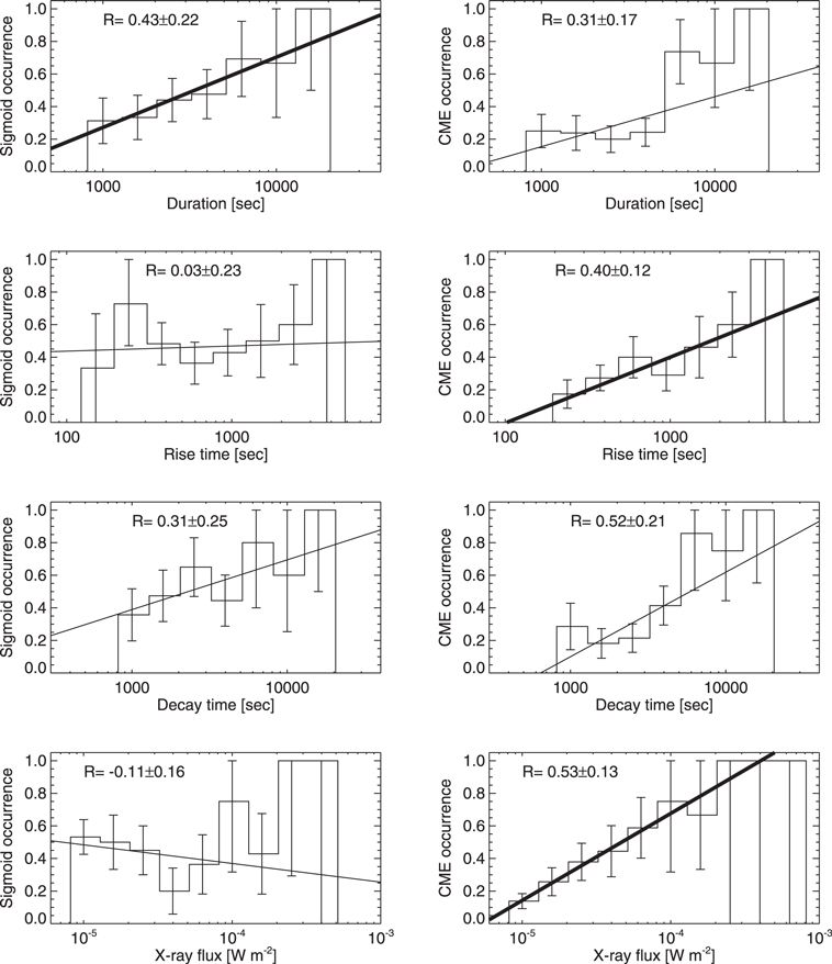
Figure 5. SGM (left) and CME (right) occurrence as functions of flare duration, rise time, decay time, and soft-X-ray peak flux for all events in which recognizable SGMs/CMEs occurred. The error bar length was estimated assuming Poisson noise. The inclined line represents the result of linear fitting.
Download figure:
Standard image High-resolution imageTable 2. Spearman's Rank Correlation Coefficient ρ, and Kendall's Rank Correlation Coefficient τ, of Occurrence Distribution in Figures 5–7
| All (211 events) | On-disk (63 events) | Limb (148 events) | ||||
|---|---|---|---|---|---|---|
| ρ | τ | ρ | τ | ρ | τ | |
| duration—SGM | 0.96 | 0.90 | 0.85 | 0.72 | 0.79 | 0.62 |
| duration—CME | 0.71 | 0.52 | 0.76 | 0.65 | 0.86 | 0.71 |
| rise time—SGM | 0.57 | 0.50 | 0.20 | 0.14 | 0.35 | 0.18 |
| rise time—CME | 0.98 | 0.93 | 0.81 | 0.69 | 0.98 | 0.93 |
| decay time—SGM | 0.75 | 0.62 | 0.93 | 0.82 | 0.44 | 0.41 |
| decay time—CME | 0.86 | 0.71 | 0.85 | 0.72 | 0.86 | 0.71 |
| X-ray flux—SGM | 0.41 | 0.25 | 0.63 | 0.49 | 0.26 | 0.18 |
| X-ray flux—CME | 0.98 | 0.92 | 0.83 | 0.68 | 0.90 | 0.78 |
Note. Bold values show the deviation from zero in the 99% confidence interval.
Download table as: ASCIITypeset image
Figure 5 shows the SGM and CME occurrence as functions of the respective flare properties. The length of the error bar is estimated assuming Poisson noise. Hence, a larger error bar is due to a smaller sample size (e.g., only one event exists at which the rise time ranges between 103.7 < trise < 103.9 s. It can be estimated whether a CME was included. Therefore, the 1σ uncertainty of the occurrence in the range equals 1.0). In order to estimate the dependence of the SGM and CME occurrence on the respective flare parameter, the histograms were fitted to a linear function using the least-squares method and considering a Poisson error scale. Only when the Spearman's rank correlation coefficient ρ and Kendall's rank correlation coefficient τ are significantly different from 0 in the 99% confidence interval, the fitted lines are shown in bold. The error value of a slope R is the 1σ uncertainty. Regarding SGM occurrence, we obtained a slope of R = 0.43 ± 0.22 for the duration, which is a positive value for a 1σ uncertainty. Regarding CME occurrence, we obtained a positive slope for two parameters: R = 0.40 ± 0.12 for the rise time, and R = 0.53 ± 0.13 for the soft-X-ray peak flux.
To compare on-disk and limb events, we derived the SGM and CME occurrence as functions of the respective flare properties. We conducted linear fitting, as above. The results are shown in Figures 6 and 7. Since the total number of events for SGMs is small (42), the occurrence error is large. For the on-disk events, the SGM occurrence as a function of the decay time possesses a steep slope (R = 0.61 ± 0.41). For the limb events, we obtained a positive slope from the CME occurrence as a function of the rise time (R = 0.45 ± 0.14), and X-ray flux (R = 0.60 ± 0.15).

Figure 6. Similar to Figure 5, but for on-disk events.
Download figure:
Standard image High-resolution image
Figure 7. Similar to Figure 5, but for limb events.
Download figure:
Standard image High-resolution image4.3. Linear Correlations between Parameters
We investigated the linear correlations between physical parameters by creating a scatter plot. Before presenting the result of this plot, we show Pearson's correlation coefficient C, Spearman's rank correlation coefficient ρ, and Kendall's rank correlation coefficient τ, between two parameters in Table 3. As in Table 2, bold values show the deviation from zero in the 99% confidence interval. As we can see, there are significant correlations between the duration, decay time, and rise time for all, on-disk, and limb events. Significant correlations are also seen between duration and CME width, decay time and CME width, duration and X-ray flux, and decay time and X-ray flux for all events. In the limb events, there is no correlation between duration and CME width, or decay time and CME width. Note that the results of linear fitting are shown later in this section but the linear model may be invalid when the rank correlation coefficient is not significantly different from 0 in the 99% confidence interval.
Table 3. Pearson's Correlation Coefficient C, Spearman's Rank Correlation Coefficient ρ, and Kendall's Rank Correlation Coefficient τ, between Two Parameters
| All (211 events) | On-disk (63 events) | Limb (148 events) | |||||||
|---|---|---|---|---|---|---|---|---|---|
| C | ρ | τ | C | ρ | τ | C | ρ | τ | |
| duration—rise time | 0.62 | 0.63 | 0.47 | 0.61 | 0.54 | 0.41 | 0.63 | 0.67 | 0.51 |
| duration—decay time | 0.97 | 0.96 | 0.85 | 0.97 | 0.96 | 0.87 | 0.97 | 0.96 | 0.84 |
| rise time—decay time | 0.45 | 0.46 | 0.32 | 0.45 | 0.38 | 0.28 | 0.45 | 0.49 | 0.35 |
| duration—CME speed | 0.19 | 0.20 | 0.15 | 0.17 | 0.22 | 0.15 | 0.19 | 0.18 | 0.14 |
| rise time—CME speed | 0.16 | 0.14 | 0.10 | 0.18 | 0.15 | 0.09 | 0.16 | 0.13 | 0.09 |
| decay time—CME speed | 0.16 | 0.19 | 0.13 | 0.13 | 0.20 | 0.12 | 0.17 | 0.18 | 0.12 |
| duration—CME width | 0.38 | 0.37 | 0.26 | 0.55 | 0.42 | 0.35 | 0.30 | 0.31 | 0.22 |
| rise time—CME width | 0.27 | 0.27 | 0.21 | 0.09 | 0.07 | 0.07 | 0.30 | 0.31 | 0.24 |
| decay time—CME width | 0.40 | 0.37 | 0.27 | 0.60 | 0.51 | 0.42 | 0.31 | 0.30 | 0.23 |
| duration—X-ray flux | 0.44 | 0.36 | 0.25 | 0.27 | 0.22 | 0.16 | 0.51 | 0.42 | 0.29 |
| rise time—X-ray flux | 0.14 | 0.10 | 0.07 | 0.05 | −0.04 | -0.03 | 0.17 | 0.16 | 0.11 |
| decay time—X-ray flux | 0.47 | 0.39 | 0.28 | 0.30 | 0.24 | 0.17 | 0.54 | 0.47 | 0.33 |
Note. Bold values show the deviation from zero in the 99% confidence interval.
Download table as: ASCIITypeset image
In Figures 8–10, we show the results of linear fitting, in which bold lines are used when the the values of ρ and τ are significantly different from 0 in the 99% confidence interval. The correlation coefficients C are shown for all (black), on-disk (red), and limb (blue) events. The correlation coefficient of the duration and decay time (middle panel) is extremely large, C = 0.97. However, C is relatively small (∼0.45) for the decay and rise time.

Figure 8. Scatter plot of duration and rise time (left panel), duration and decay time (middle panel), rise time and decay time (right panel). The red and blue points mark on-disk and limb events, respectively.
Download figure:
Standard image High-resolution image
Figure 9. Scatter plot of duration and CME speed (top left), rise time and CME speed (top middle), decay time and CME speed (top right), duration and CME width (bottom left), rise time and CME width (bottom middle), and decay time and CME width (bottom right). The red and blue points mark the on-disk and limb events, respectively.
Download figure:
Standard image High-resolution imageIn Figure 9 the correlation coefficients are small and similar for all relations for all events, C = 0.16–0.40. In the on-disk events, however, the correlation coefficient between the duration and CME width, and decay time and CME width is relatively high, C = 0.55, 0.60. The low correlation in the limb events may come from the upper limit of the CME width (360°). There are more limb events than on-disk events. As the number of CME events with 360° width increases, the correlation coefficient decreases.
In Figure 10 the correlation coefficients for all events between the duration and X-ray class, and the decay time and X-ray class, are relatively large: C = 0.44, 0.47, respectively. In contrast, that of rise time and X-ray class is quite small, C = 0.14.

Figure 10. Scatter plot of duration and X-ray class (left panel), rise time and X-ray class (middle panel), and decay time and X-ray class (right panel). The red and blue points mark the on-disk and limb events, respectively.
Download figure:
Standard image High-resolution image4.4. Association Between Parameters
Table 4 summarizes the occurrence probabilities. Those of LXC events and LDEs constitute roughly half. As described above, in five of 211 flare events, data are lacking in GOES. In addition, certain events occur at decay times of other events, which makes it difficult to evaluate their duration. We excluded these events from our analysis. Thus, there are 186 events in the second row in Table 4 instead of 211. The SGMs are accompanied by flares in approximately half of the events. The CME occurrence probability is 32.2%, which is slightly lower than those for LXCs, LDEs, and SGMs. No occurrence probabilities show significant variation among all, on-disk, and limb events.
Table 4. Occurrence Probability of Events
| All | On-disk | Limb | ||||
|---|---|---|---|---|---|---|
| Number | Probability | Number | Probability | Number | Probability | |
| LXC | 105/211 | 49.8 ± 4.9% | 32/63 | 50.8 ± 9.0% | 73/148 | 49.3 ± 5.8% |
| LDE | 89/186 | 47.8 ± 5.1% | 29/53 | 54.7 ± 10.2% | 60/133 | 45.1 ± 5.8% |
| SGM | 58/120 | 48.3 ± 6.3% | 21/42 | 50.0 ± 10.9% | 37/78 | 47.4 ± 7.8% |
| CME | 57/177 | 32.2 ± 4.3% | 15/51 | 29.4 ± 7.6% | 42/126 | 33.3 ± 5.1% |
Download table as: ASCIITypeset image
The contingency tables of each two sets regarding LXC, LDE, SGM, and CME are summarized in Table 5. The fourth and seventh columns show the intersection probabilities and those of negation on both events. The fifth and sixth columns present the results for the intersection probability of negation on one event. In the SGM–CME analysis, many unaccompanied SGMs exist (39.2%), but the quantity of CMEs without SGMs is much lower (12.8%). Many LXC events exist without CMEs (25.4%), but the quantity of CMEs without LXC events is much lower (9.6%). Further, LDEs without CME are observed (26.1%), but the occurrence probability of CMEs without LDEs is much lower (8.9%). Nevertheless, no dependence on the observation location could be observed (on-disk or limb) for LXC–LDE, LXC–SGM, or LDE–SGM. The ϕ coefficient is shown in the eighth column. We employ 0.2 as the threshold value for a weak association. A ϕ coefficient larger than 0.2 is shown in bold face in Table 5. A dependence on observation location is observed. In all and limb cases, the ϕ coefficients of all pairs from LXC–LDE–CME show relatively high values. On the other hand, those from LDE–SGM–CME are larger than 0.2 but those of LXC–CME and LXC–SGM are not in the on-disk case.
Table 5. Contingency Table of Events and Mean Square Contingency Coefficient
| A | B | Ntot | ϕ | |||||
|---|---|---|---|---|---|---|---|---|
| All | ||||||||
| LXC | LDE | 186 | 28.5 ± 3.8% (53) | 19.4 ± 3.2% (36) | 18.4 ± 3.1% (34) | 33.9 ± 4.3% (63) | 0.25 | |
| LXC | SGM | 120 | 21.7 ± 4.2% (26) | 26.7 ± 4.7% (32) | 26.7 ± 4.7% (32) | 25.0 ± 4.6% (30) | 0.07 | |
| LXC | CME | 177 | 22.6 ± 3.6% (40) | 9.6 ± 2.3% (17) | 25.4 ± 3.8% (45) | 42.1 ± 4.9% (75) | 0.31 | |
| LDE | SGM | 108 | 27.8 ± 5.1% (30) | 21.3 ± 4.4% (23) | 23.2 ± 4.6% (25) | 27.8 ± 5.1% (30) | 0.11 | |
| SGM | CME | 102 | 13.7 ± 3.7% (14) | 12.8 ± 3.5% (13) | 39.2 ± 6.2% (40) | 34.3 ± 5.8% (35) | 0.01 | |
| CME | LDE | 157 | 24.8 ± 4.0% (39) | 26.1 ± 4.1% (41) | 8.9 ± 2.4% (14) | 40.1 ± 5.1% (63) | 0.32 | |
| On-disk | ||||||||
| LXC | LDE | 53 | 26.4 ± 7.1% (14) | 28.3 ± 7.3% (15) | 22.6 ± 6.5% (12) | 22.6 ± 6.5% (12) | 0.02 | |
| LXC | SGM | 42 | 28.6 ± 9.0% (12) | 21.4 ± 7.1% (9) | 21.4 ± 7.1% (9) | 28.6 ± 8.3% (12) | 0.14 | |
| LXC | CME | 51 | 15.7 ± 5.5% (8) | 13.7 ± 5.2% (7) | 27.5 ± 7.3% (14) | 43.1 ± 9.2% (22) | 0.13 | |
| LDE | SGM | 39 | 30.8 ± 8.7% (12) | 18.0 ± 6.8% (7) | 18.0 ± 6.8% (7) | 33.3 ± 9.3% (13) | 0.28 | |
| SGM | CME | 34 | 20.6 ± 7.8% (7) | 8.8 ± 5.1% (3) | 32.4 ± 9.8% (11) | 38.3 ± 10.6% (13) | 0.22 | |
| CME | LDE | 44 | 25.0 ± 7.5% (11) | 36.4 ± 9.1% (16) | 6.8 ± 3.9% (3) | 31.8 ± 8.5% (14) | 0.24 | |
| Limb | ||||||||
| LXC | LDE | 133 | 29.3 ± 4.7% (39) | 15.8 ± 3.5% (21) | 16.5 ± 3.5% (22) | 38.4 ± 5.4% (51) | 0.34 | |
| LXC | SGM | 78 | 18.0 ± 4.8% (14) | 29.5 ± 6.1% (23) | 29.5 ± 6.1% (23) | 23.1 ± 5.4% (18) | 0.18 | |
| LXC | CME | 126 | 25.4 ± 4.5% (32) | 7.9 ± 2.5% (10) | 24.6 ± 4.4% (31) | 42.1 ± 5.8% (53) | 0.37 | |
| LDE | SGM | 69 | 26.1 ± 6.2% (18) | 23.2 ± 5.8% (16) | 26.1 ± 6.2% (18) | 24.6 ± 6.0% (17) | 0.02 | |
| SGM | CME | 68 | 10.3 ± 3.9% (7) | 14.7 ± 4.7% (10) | 41.2 ± 7.8% (28) | 33.8 ± 7.1% (23) | 0.12 | |
| CME | LDE | 113 | 24.8 ± 4.7% (27) | 22.1 ± 4.4% (25) | 9.7 ± 2.9% (11) | 43.4 ± 6.2% (49) | 0.35 | |


Download table as: ASCIITypeset image
The results of association analysis for the intersection sets are summarized in Table 6. The parameter Pind represents the intersection probability assuming that two sets are independent, Pind = P(A) × P(B); Pobs corresponds to the intersection of the events according to observations, in Table 5; ΔP is the difference between Pind and Pobs. The error value σΔ is obtained from the propagation of the error values assuming independent σind and σobs, i.e., . For all events, LXC–CME and CME–LDE show significant probabilities (1.25 and 1.42), while LXC–SGM and SGM–CME exhibit smaller probabilities (−0.36 and −0.33) compared to other events. Although there are no significant probabilities in the on-disk events, LXC–SGM, SGM–CME, and CME–LDE show comparatively higher probabilities. For limb events, the CME–LXC and CME–LDE values show significant dependence.


Table 6. Association Analysis for Intersection Sets
| Pind ± σind | Pobs ± σobs | ΔP ± σΔ | ΔP/σΔ | ||
|---|---|---|---|---|---|
| All | |||||
| LXC-LDE | 23.8 ± 4.9% | 28.5 ± 3.9% | 4.7 ± 6.3% | 0.75 | |
| LXC-SGM | 24.2 ± 5.5% | 21.7 ± 4.2% | −2.5 ± 6.9% | −0.36 | |
| LXC-CME | 16.1 ± 3.7% | 22.6 ± 3.6% | 6.5 ± 5.2% | 1.25 | |
| LDE-SGM | 23.1 ± 5.5% | 27.8 ± 5.1% | 4.7 ± 7.5% | 0.63 | |
| SGM-CME | 15.5 ± 4.1% | 13.7 ± 3.7% | −1.8 ± 5.5% | −0.33 | |
| CME-LDE | 15.4 ± 3.7% | 24.8 ± 4.0% | 9.4 ± 5.4% | 1.74 | |
| On-disk | |||||
| LXC-LDE | 27.8 ± 10.1% | 26.4 ± 7.1% | −1.4 ± 12.3% | −0.11 | |
| LXC-SGM | 25.4 ± 10.0% | 34.9 ± 9.0% | 9.5 ± 13.5% | 0.70 | |
| LXC-CME | 14.9 ± 6.5% | 15.7 ± 5.5% | −0.8 ± 8.5% | −0.09 | |
| LDE-SGM | 27.4 ± 11.1% | 30.8 ± 8.9% | 3.4 ± 14.2% | 0.24 | |
| SGM-CME | 14.7 ± 7.2% | 20.6 ± 7.8% | 5.9 ± 10.6% | 0.56 | |
| CME-LDE | 16.1 ± 7.2% | 25.0 ± 7.5% | 8.9 ± 10.4% | 0.86 | |
| Limb | |||||
| LXC-LDE | 22.2 ± 5.5% | 29.3 ± 4.7% | 7.1 ± 7.2% | 0.99 | |
| LXC-SGM | 23.4 ± 4.4% | 18.0 ± 4.8% | −5.4 ± 6.5% | −0.83 | |
| LXC-CME | 16.4 ± 6.6% | 25.4 ± 4.5% | 9.0 ± 8.0% | 1.13 | |
| LDE-SGM | 21.4 ± 6.3% | 26.1 ± 6.2% | 4.7 ± 8.8% | 0.53 | |
| SGM-CME | 15.8 ± 5.0% | 10.3 ± 3.9% | −5.5 ± 6.3% | −0.87 | |
| CME-LDE | 15.0 ± 4.2% | 24.8 ± 4.7% | 9.8 ± 6.3% | 1.56 | |
Download table as: ASCIITypeset image
4.5. KS and AD Tests
We conducted KS and AD tests and estimated the dependence of the SGMs and CMEs on the flare parameters. We selected 58 events with an SGM and 62 events without (see Table 1). Also, we selected 57 events with a CME and 120 events (see Table 1).
Figure 11 shows the CDFs.

Figure 11. Cumulative distribution functions of SGMs (left side) and CMEs (right side) for flare duration, rise time, decay time, and soft-X-ray peak flux. The solid curves represent the CDF for events with SGMs (CMEs), and the dashed curves show the CDF for the events without SGMs (CMEs). The vertical dash–dot lines indicate the maximal deviation between two CDFs. The black, red, and blue lines represent all events, on-disk events, and limb events, respectively.
Download figure:
Standard image High-resolution imageTables 7 and 8 show the values of the KS and AD statistics regarding SGMs and CMEs, respectively. Bold values indicate than the 99% confidence level (α < 0.01). According to Table 7, SGM occurrence is not significantly related to all parameters. However, the statistics of both KS and AD tests show relatively larger values in the decay time and duration for all and for the on-disk events, and is less related to the rise time and soft-X-ray peak flux for these events. Because the number of the sample of the limb events is larger than that of the on-disk events, the value of the limb events is lower compared to on-disk events. Therefore, the probability tends to be smaller in the limb events than the on-disk events in the KS test.

Table 7. KS and AD Statistics for Each Condition for SGMs. Bold Values Show More Than 99% Confidence
| All (211 events) | On-disk (63 events) | Limb (148 events) | ||||
|---|---|---|---|---|---|---|
| KS Statistic | AD Statistic | KS Statistic | AD Statistic | KS Statistic | AD Statistic | |
| duration | 0.20 | 1.49 | 0.43 | 3.2 | 0.12 | −0.78 |
| rise time | 0.12 | −0.18 | 0.23 | −0.58 | 0.18 | −0.23 |
| decay time | 0.26 | 2.2 | 0.43 | 3.7 | 0.17 | −0.60 |
| X-ray flux | 0.13 | −0.27 | 0.28 | 0.24 | 0.31 | 1.2 |
Download table as: ASCIITypeset image
Table 8. KS and AD Statistics for Each Condition for CMEs. Bold Values Show More Than 99% Confidence
| All (211 events) | On-disk (63 events) | Limb (148 events) | ||||
|---|---|---|---|---|---|---|
| KS statistic | AD statistic | KS statistic | AD statistic | KS statistic | AD statistic | |
| duration | 0.44 | 18.0 | 0.59 | 7.0 | 0.42 | 11.6 |
| rise time | 0.23 | 5.0 | 0.30 | 0.38 | 0.26 | 3.7 |
| decay time | 0.43 | 18.3 | 0.59 | 7.1 | 0.40 | 12.0 |
| X-ray flux | 0.41 | 17.1 | 0.43 | 2.3 | 0.49 | 15.0 |
Download table as: ASCIITypeset image
According to Table 8, in a confidence interval of 99%, the CME occurrence is related to the flare duration and decay time for all, on-disk, and limb events and to the soft-X-ray peak flux for all and the limb events. Only for all events is the rise time related to the CME occurrence in the AD test.
5. Discussion
5.1. CMEs
CME occurrences as functions of duration, rise time, and decay time show a positive slope in Figure 5, while the duration and the decay time do not show significant dependence at the 99% confidence level. Toriumi et al. (2017) also compared the histograms of the duration and decay time for eruptive and noneruptive events. In their results, the decay time histogram for eruptive events shows large values for long decay times. On the other hand their histograms of duration show little difference between eruptive and noneruptive events, whereas CME occurrence as a function of duration shows a positive slope in our study. Their conclusion that a longer decay time tends to produce CMEs is consistent with our result. However, the decay time and the duration show a similar trend in our study. This is due to the different definition of decay time. They define the decay time as the e-folding time. Therefore, their duration is more prone to being affected by the rise time than the decay time obtained using our definition. In our definition, the rise time is an order of magnitude shorter than the decay time. The duration is determined largely by the decay time from Equation (3). The relation between CME occurrence and decay time can be understood by examining the relation between decay time and flaring loop length. It is known that the decay time depends linearly on the flaring loop length (in the global thermodynamic timescale) (Reale 2002):

where L9 and T7 are loop length and temperature in 109 cm and 107 K, respectively. When a CME occurs, the reconnected field lines, i.e., flare loops, must be large because the reconnection point becomes higher and higher as the flare proceeds. Consequently, the decay time tends to be large.
In limb events, CME occurrence shows a strong dependence on X-ray flux (R = 0.60 ± 0.15), which is consistent with the results in Yashiro et al. (2006). They showed that the value of the slope is R = 0.332 for X-ray flux without on-disk events. Their is different in 1σ uncertainty from our results. We suspect that this is mainly due to different event numbers. There are 16 X-class flares in our study, and 98 in Yashiro et al. (2006). Our results indicate that CMEs are associated with approximately all events whose X-ray flux is larger than 10−3.9 W m−2. This is also consistent with the results in Yashiro et al. (2006).
In Figure 9, fewer correlations exist between duration, rise time, CME width, and CME speed. The correlation of CME speed and duration measures 0.19, although Toriumi et al. (2017) reported a correlation coefficient of 0.50. It should be noted that they selected events at heliographic coordinates less than 45◦ from the disk center, which makes the CME speed uncertain. Furthermore, there are more (57) CME events in our study than in theirs (32). Therefore our results, indicating a lower correlation between duration and CME speed, should be more reliable. In addition, there is more sophisticated way of deriving the CME speed due to Lugaz et al. (2010), who studied the azimuthal property using stereoscopic observations. The application of this method to a statistical study will be a future undertaking. Regarding the CME width, it appears that the correlation coefficients are larger compared to those of the CME speed. This results from the fact that large CME sizes cause larger flare loops and longer duration and decay time, as discussed above.
In Table 5, LXC–CME and LDE–CME show a relatively high association (ϕ > 0.2) in all events and limb events, while LXC–CME does not show high association in on-disk events. The lower association between LXCs and CMEs in on-disk events might be due to their small number. This result indicates that the relation between LDEs and CMEs is stronger than that between LXCs and CMEs. This might be also affected by the detection uncertainty of each phenomenon and structure. In other words, limb events have less uncertainty for CME detection, while it is difficult to associate CMEs with flares for on-disk events. Our association analysis for intersection sets in Table 6 indicates a high dependence for LXC–CME (ΔP/σΔ = 1.25) and CME–LDE (ΔP/σΔ = 1.74) for all events. This is consistent with the results of the occurrence rate in Figure 5. However, several relations show a dependence on the position of the flare event.
The KS and AD tests indicate that in a confidence interval of 99%, the CME is related to longer duration and decay time. Further, for the limb and all events, the X-ray flux is significantly related to the CMEs. Thus, the relation between CME association and X-ray flux strengthens in limb events, which reflects that CMEs are more easily detected at the solar limb than inside the solar disk.
5.2. SGMs
In Figure 5, as in the case of SGM occurrence, the positive values of the slope R = 0.43 ± 0.22 for duration. Thus, duration tends to increase when a sigmoidal structure exists. A sigmoidal structure means highly twisted magnetic field lines and is usually formed in large active regions. Hence, sigmoidal structures tend to have long field lines and can lead to long-duration flares from the discussion above. From Figures 6 and 7, SGM occurrence as a function of X-ray flux appears to exhibit a positive slope, although their dependences do not show significant correlation. A sigmoidal structure implies a large free energy in the 3D magnetic field. Naturally, a large free energy can lead to large flares. Our results, however, do not show significant evidence that a larger free energy is needed to produce larger flares for on-disk events.
From the KS and AD tests, we did not find a relation between the flare parameters and SGM existence in the 99% confidence interval. However, there were weak relations between some parameters. For all events (black line in figures), SGM existence is related to a longer decay time (probability 0.045) and for the on-disk events (red line), it is related to a longer duration and longer decay time (the probabilities are 0.037 and 0.035). In contrast, for limb events (blue line), SGM existence is not related to the duration, rise time,or decay time due to its detection uncertainty regarding active regions far away from the disk center. Moreover, according to the CDF curves in the panel of the fourth row on the left side of Figure 11, if an SGM exists, the X-ray flux becomes large only for on-disk events.
In this study, we determined SGM existence by visual inspection aided by the detection of the bright region described in Section 3.1.3. We plan to develop a fully automatic SGM detection method by applying automatic thinning processing to the sigmoidal region. Although the thinning processing of the spread area is difficult in general, one promising method is OCCULT-2, developed by Aschwanden et al. (2013).
5.3. Relation between CMEs and SGMs
The appearance of X-ray SGMs has been considered as an indicator for eruptive flares (Canfield et al. 1999). In their results, 50% of the non-sigmoidal region produced eruptive events, while 84% of the sigmoidal region produced these events. Our association analysis in Tables 5 and 6, however, indicates that there is less dependence of SGMs on CMEs in all and the limb events. As discussed above, we suspect that in the limb events, sigmoidal structures are difficult to identify due to projection effects. In the on-disk events, on the other hand, the CME–SGM relation shows comparatively high dependence (ϕ > 0.2) in Table 5, while it is not significant in Table 6. Our results in Table 5 show only 39% of sigmoidal structures produce CMEs in the on-disk events. These results show that the sigmoidal structure does not necessarily lead to eruptive flares. The result in Table 5 also supports this statement. Focusing on the on-disk events, while 20.6% of the flare events have both SGMs and CMEs, 32.4% of the flare events have sigmoidal structure but do not produce CMEs. Another important result is that there are extremely few flare events with CMEs and without SGMs. This result shows that the sigmoidal structure is necessary (but not sufficient) factor for the occurrence of CMEs. The methods for identifying sigmoidal structures may result in a deviation of our results from those of Canfield et al. (1999). For example, smaller sigmoidal structures, shown in the bottom panel of Figure 2, were identified in our study. This might reduce the number of non-sigmoidal but eruptive events.
Tripathi et al. (2004) studied the relation between the post-eruptive arcade (PEA) and CMEs and found that almost all PEAs as observed by SOHO/EIT were associated with CMEs. They also studied the length of the PEA at each latitude. It would be an interesting future topic to study the relation between the length of SGMs and the PEA.
6. Summary
We performed statistical analyses to compare the dependence among the parameters of SGM existence, CME existence, duration, decay time, rise time, X-ray peak flux, CME speeds, and CME width, based on five analyses: occurrence rate analysis, linear-correlation analysis, association analysis, the KS test, and the AD test. Our statistical analysis reproduced some results consistent with previous studies. The dependence of CME occurrence on X-ray flux is consistent with that found by Yashiro et al. (2006). The result that longer decay time flares tend to produce CMEs is also consistent with that of Toriumi et al. (2017). Regarding sigmoidal structures, Canfield et al. (1999) investigated the eruptivity of SGMs based on soft-X-ray images only. In contrast, our statistical analysis shows a dependence between SGMs and CMEs by comparing soft X-ray images with a comprehensive CME catalog from SOHO/LASCO. One of our new results is that the dependence between SGMs and CMEs changes with the location of the event, probably due to the uncertainty in the detection of sigmoidal structures. Another new result is that while flare events with SGMs do not necessarily produce CMEs, the latter without the former are very few.
In terms of space weather, the important phenomenon to predict is CME occurrence. We conclude that sigmoidal structure shows a comparatively strong dependence on CME occurrence in on-disk events, whereas the decay time, duration, and X-ray class depend on CME occurrence in on-disk and limb events. Since CMEs produced on-disk have a high probability to have a great impact on the Earth, sigmoidal structures are very useful to predict approaching CMEs. In addition, sigmoidal structures are often created more than tens of hours before the flare onset, thereby enabling an early prediction of CMEs. However, regarding limb events, the decay time, duration, and X-ray class events help to predict CMEs, but can only be used after the occurrence of solar flares.
We thank the referee for constructive criticisms and valuable comments, allowing us to improve the manuscript significantly. Hinode is a Japanese mission developed and launched by ISAS/JAXA, in collaboration with NAOJ as domestic partner, and NASA and STFC (UK) as international partners. The mission is operated by these agencies in cooperation with ESA and NSC (Norway). This study was carried out using the Hinode Flare Catalog (https://hinode.isee.nagoya-u.ac.jp/flare_catalogue/), which is maintained by ISAS/JAXA and the Institute for Space–Earth Environmental Research (ISEE) at Nagoya University. A part of this study was carried out by the joint research program of ISEE. The CME catalog is generated and maintained at the CDAW Data Center at NASA and The Catholic University of America in cooperation with the Naval Research Laboratory (USA). SOHO is an international cooperation project between ESA and NASA. This work was supported by MEXT/JSPS KAKENHI grant No. JP15H05814.
Footnotes
- 6
- 7
- 8
The detection code is available from https://zenodo.org/record/1484859#.W_yURhP7TVA.