Abstract
Three approaches to describing the separation of charges in near-cathode regions of high-pressure arc discharges are compared. The first approach employs a single set of equations, including the Poisson equation, in the whole interelectrode gap. The second approach employs a fully non-equilibrium description of the quasi-neutral bulk plasma, complemented with a newly developed description of the space-charge sheaths. The third, and the simplest, approach exploits the fact that significant power is deposited by the arc power supply into the near-cathode plasma layer, which allows one to simulate the plasma–cathode interaction to the first approximation independently of processes in the bulk plasma. It is found that results given by the different models are generally in good agreement, and in some cases the agreement is even surprisingly good. It follows that the predicted integral characteristics of the plasma–cathode interaction are not strongly affected by details of the model provided that the basic physics is right.
Export citation and abstract BibTeX RIS
1. Introduction
Impressive advances achieved in the modelling of high-pressure arc discharges have been summarized in recent review papers [1, 2]. Significant improvements have been acknowledged, attained over the last 15 years in the modelling of cathode and anode phenomena in order to couple the electrodes with the bulk plasma in a general model. On the other hand, a clear need for further improvement has been pointed out, in the first place, as far as the cathode phenomena are concerned. It is worth noting that the near-cathode space-charge sheath plays an important role in the energy balance of arc discharges: substantial electric power is deposited by the arc power supply into the sheath. Therefore, an adequate account of the near-cathode sheath in the modelling of high-pressure arc discharges is indispensable for the modelling to be physically justified.
A number of different models to account for near-cathode sheaths in numerical simulations of high-pressure arc discharges have been described in the literature. The aim of this work is to systematize these models and to compare the results wherever possible.
The outline of the paper is as follows. Different approaches to accounting for near-cathode sheaths in numerical models of high-pressure arc discharges are discussed in section 2. Characteristics of the cathodic part of arc discharges predicted by the different approaches are compared in sections 3 and 4. Conclusions are summarized in section 5. Boundary conditions describing positive and negative space-charge sheaths in non-equilibrium models of arc discharges are derived in the appendix.
2. Different ways to account for near-cathode sheaths in numerical models of high-pressure arc discharges
The physics of current transfer to electrodes of high-pressure arc discharges is rather complex and involves processes characterized by substantially different length scales, such as the Debye length, the mean free paths of the ions, electrons and neutral atoms, the lengths of Maxwellization of emitted electrons and the relaxation of their energy, the ionization length etc. There are a large number of publications dedicated to different aspects of near-electrode physics in arc discharges, e.g. the reviews [3–12]. Without trying to provide another review, we will rather focus on a particular aspect: methods of quantitative description of charge separation in the near-cathode region.
2.1. Unified modelling
A standard approach to the simulation of cold plasmas is to use a single set of equations, including the Poisson equation, in the whole interelectrode gap, without a priori dividing the computation domain into quasi-neutral plasma and space-charge sheaths. However, such unified modelling is highly computationally intensive in the case of arc plasmas, where the density of charged particles is very high, space-charge sheaths occupy only a tiny fraction of the computation domain, and the separation of charges in the bulk plasma is very small. Up to now this approach has been applied only to one-dimensional (1D) models of near-cathode and near-anode regions, which separate the electrodes from the bulk of the arc where local thermodynamic equilibrium (LTE) holds [13–15].
A result of the unified modelling of the near-cathode regions [13] relevant to this work is that the energy flux in typical situations is directed not from the bulk plasma to the near-cathode layer, but from the layer into the bulk. In other words, it is the near-cathode layer that heats the arc bulk rather than the other way around. This originates in significant power deposited by the arc power supply into the near-cathode space-charge sheath and eventually into the adjacent ionization layer; part of this power is transported to the cathode surface, thus heating it to temperatures sufficient for electron emission, and the rest is transported into the bulk plasma. A consequence is that the plasma–cathode interaction is governed primarily by processes in the thin near-cathode plasma layer and is to the first approximation independent of processes in the arc bulk.
2.2. Separate treatment of the plasma bulk and space-charge sheaths
An alternative to unified modelling is to employ separate descriptions of the bulk quasi-neutral plasma and space-charge sheaths formed near solid surfaces (electrodes and insulators).
The bulk plasma of high-pressure arc discharges has been described in the literature by models of different levels of complexity. Most works employ models based on the assumption of LTE, which amounts to assuming the ionization (Saha) equilibrium and equilibrium between the electron and heavy-particle temperatures Te and Th; see e.g. reviews [1, 2, 16]. Many papers employ the so-called 2T models, which take into account deviations between Te and Th but assume ionization equilibrium, e.g. the review [17]. Other papers, vice versa, assume  but do not assume ionization equilibrium, e.g. [18–22]. Finally, there are fully non-equilibrium models, which rely on assumptions of neither thermal nor ionization equilibrium; e.g. [23–27].
Matching of solutions for the bulk plasma and sheaths depends on the models used for each of these regions and is considered in subsequent sections.
2.2.1. NLTE-sheath approach.
If the bulk plasma is described by means of a fully non-equilibrium model, solutions for the bulk plasma and the sheaths may be matched directly. In what follows, such an approach will be referred to as the NLTE-sheath approach.
Boundary conditions for the bulk plasma equations, describing space-charge sheaths in the framework of this approach, are derived in the appendix. A numerical realization of the NLTE-sheath approach, based on these boundary conditions, is described in [28]. The equations describing the bulk plasma in [28] are the same as those used in the unified modelling [13, 14] except that the Poisson equation is replaced by the quasi-neutrality condition; these equations contain a full account of diffusion of the species, also in Ohm's law, and this made the matching possible. The equations of heat conduction and current continuity are solved inside the electrodes.
Note that transport processes in the bulk plasma are dominated by collisions under conditions of high-pressure arc discharges, which implies a description by means of hydrodynamics equations. (For example, in [28] transport of the ions and the electrons is described in terms of the Stefan–Maxwell equations.) Therefore, a direct matching with a sheath solution is possible, strictly speaking, only if the sheath is assumed to be collision-dominated. In this sense, the matching conditions derived in the appendix for the case of a sheath with collisionless ions are approximate.
2.2.2. 2T-ionization layer-sheath approach.
If the bulk plasma is described by means of a 2T model, one needs to consider an ionization layer (e.g. [9]): a thin layer of quasi-neutral plasma separating the sheath from the region where ionization equilibrium holds, i.e. a layer where deviations from ionization equilibrium are localized. An adequate account of the ionization layer is important for evaluation of the ion flux to the surface, which is generated in this layer.
For numerical realization, one needs a model of a thin near-surface layer comprising a quasi-neutral ionization layer and a space-charge sheath with negligible volume ionization and recombination, which can serve as an interface separating the 2T ionization-equilibrium bulk plasma from the solid surface. Such models for near-cathode layers in high-pressure arc discharges were developed in [29–33]; see [9] for discussion and further references.
On joining a model of a near-surface layer, comprising a quasi-neutral ionization layer and a space-charge sheath, with a 2T model for the bulk plasma and with equations for heat conduction and current continuity inside the electrodes, one obtains a model for the arc as a whole. Such an approach may be termed the 2T-ionization layer-sheath approach and was realized in [34, 35] with the use of the model of near-cathode layers developed in [29–31].
As mentioned in section 2.1, the plasma–cathode interaction is to the first approximation independent of processes in the plasma bulk. This feature is reflected in the 2T-ionization layer-sheath approach in a natural way: the cathodic part of the discharge (the cathode and the near-cathode plasma layer) is computed independently of the plasma bulk. After this has been done, 2T equations describing the bulk are solved with the boundary conditions at the cathode surface being distributions of the surface temperature, current density and electron temperature in the ionization layer, computed as a part of the cathodic part of the solution.
The first step of this approach, i.e. calculation of the cathodic part of the arc, is sometimes called the model of nonlinear surface heating. It was proposed for the first time apparently in [36]; see [9] for discussion and further references. By now this model has gone through a detailed experimental validation for low-current arc discharges. One can specifically mention the works of Mentel and coworkers [37], in particular; further examples of experimental verification and references can be found in [9, 38–40].
This work is concerned with comparison of characteristics of the cathodic part of the arc given by different models. No solution for the bulk plasma is needed to this end, therefore the 2T-ionization layer-sheath approach amounts to using the model of nonlinear surface heating in the context of this work.
2.2.3. Other possible approaches.
An approach similar to the 2T-ionization layer-sheath approach may be devised on the basis of the LTE description of the bulk plasma, with the near-surface layer comprising, in addition to the space-charge sheath and the ionization layer, also a layer of thermal non-equilibrium: a layer adjacent to the ionization layer, beyond which the equality  holds, e.g. [9]. A variant of the approach employing the LTE description of the bulk plasma was considered in [41, 42]. Another variant of this approach can in principle be developed on the basis of simulations [13–15].
One could think of devising a similar approach also on the basis of a bulk plasma model accounting for deviations from ionization equilibrium but assuming  . The near-surface layer should comprise the sheath and the layer of thermal non-equilibrium in this case. However, this approach will be consistent provided that thermal equilibrium breaks down closer to the surface than the ionization equilibrium does, which is not a typical case as demonstrated by figures 1, 3 and 5 of [13].
3. Comparing results from the unified modelling and the model of nonlinear surface heating
The rest of this work is concerned with comparing characteristics of the cathodic part of arc discharges computed by means of three approaches: the unified modelling, the NLTE-sheath approach and the model of nonlinear surface heating. Since the unified modelling has been performed until now only in 1D cases [13–15], while the NLTE-sheath approach has been realized only for the 2D (axially symmetric) case [28], we cannot compare all three approaches at once. In this section, we compare the unified modelling and the model of nonlinear surface heating. The NLTE-sheath approach and the model of nonlinear surface heating are compared in the next section.
Let us consider an arc cathode having the shape of a right cylinder with the base being externally cooled; the electrical conductivity of the cathode material is high enough so that Joule heat production in the cathode body is negligible; the lateral surface is thermally and electrically insulated, so the energy flux and the electric current from the plasma enter the cathode through the front surface and leave it through the base. The heat conduction equation in the cathode body admits a 1D solution in this geometry, with the temperature distribution varying only in the axial direction and all parameters being constant along the cathode surface. This makes such geometry a convenient test case for the unified modelling.
More precisely, we compare characteristics of the cathodic part of the discharge computed by means of two approaches. In the framework of the first approach, the near-cathode region, separating the cathode from the bulk plasma where LTE holds, is simulated by means of the 1D unified modelling code [13]. The cathode bulk is described by the 1D solution of the heat conduction equation, with the energy flux from the plasma to the cathode surface being matched to the heat flux from the surface into the cathode bulk. The other approach is the model of nonlinear surface heating, based on the model of the near-cathode layer [29–31] (a summary of equations of this model can be found in [43]) and realized by means of a tool available on the internet [44]. While the tool is capable of computing both the diffuse and spot modes of current transfer, the results given here refer to the diffuse mode, where the distribution of temperature in the cathode is 1D.
All the results of this work refer to the cathode material being tungsten and the plasma-producing gas being argon at 1 bar, except for figure 6 which refers to mercury vapor at 200 bar. Simulations reported in this section refer to a cathode height equal to 1 cm with the bottom of the cathode maintained at room temperature.
The choice of calculation results to compare is not quite trivial since the unified modelling [13] and the model of the near-cathode layer [29–31] involve different sets of variables. The most natural choice seems to be as follows. The results will be compared for the same value of the current density, which is equivalent to the same value of the arc current in the 1D case being considered. The parameters to be compared are the cathode surface temperature  ; the near-cathode voltage U; the sheath voltage Ush; the average electron temperature in the ionization layer, Teil; the densities of the ion current to the cathode surface, jiw, the electron emission current, jem, and the current of fast plasma electrons counter-diffusing to the cathode surface against the sheath electric field, jCD; the density of the net energy flux to the cathode surface,
  ; densities of energy fluxes transported to the cathode surface by the heavy particles and the fast plasma electrons, qhw, qCD, and from the cathode surface by the emitted electrons, qem. All these quantities appear in a natural way in the model of the near-cathode layer [29–31], but most of them have not been expressly specified in the unified modelling [13] and for completeness need to be related to the variables employed there. The quantities jCD, qem and qCD are expressed as
where Af is the work function of the cathode material and the subscript 'w' in the unified model means that the corresponding quantity (in this case, the electron number density ne or temperature Te) is evaluated at the cathode surface. The sheath was identified in the results of unified modelling as a near-cathode region beyond which the charge separation is below  . The ionization layer was identified as a region adjacent to the sheath beyond which the deviation of the charged particle density from the value nb obtained from the Saha equation, evaluated in terms of local values of Te and Th, is below
  . (More precisely,
  was obtained from the assumption of a local balance of ionization and recombination with account of radiation escape. It deviates from the Saha value if the electron number density is of the order of 1021m−3 or smaller; see figure 5(a) of [13].) Ush and U have been evaluated as potential differences between the edge of the sheath or the ionization layer, respectively, and the cathode. Teil was evaluated as the average of the values of Te at the edge of the space-charge sheath (which represents the inner boundary of the ionization layer) and at the edge of the ionization layer.
Densities of energy fluxes transported by each particle species in the direction of the cathode in the framework of the unified model are defined as (see equation (31) of [13])
where the x-axis is directed from the cathode into the plasma,  and
and  are the density of flux in the direction of the cathode and the thermal conductivity of species α (
 ), Ai is the ionization energy and Aitd designates the term accounting for the effect inverse to the thermal diffusion (the second term on the rhs of equation (15) of [13]). The density of energy flux transported in the direction of the cathode by the heavy particles is
  .
.
A comparison of the above-listed quantities as functions of the current density is shown in figure 1. The agreement between the two approaches is good, except for a discrepancy in the current density and energy flux transported by the fast plasma electrons ( jCD, qCD) occurring in the range  A m−2. This discrepancy, however, has little relevance since contributions of the plasma electrons in this range are small anyway:
  ,
,  .
.

Figure 1. Parameters of the cathodic part of the arc computed with the use of the unified modelling (solid) and the model of nonlinear surface heating (dotted).
Download figure:
Standard image High-resolution imageThe net electron energy flux to the cathode surface is  . (In the framework of the unified model, this expression conforms to equation (3) evaluated at x = 0, which can be verified with the use of the boundary condition (25) of [13].) It is seen from figure 1(c) that
  for both models, i.e. cooling of the cathode by thermionic emission prevails over the heating by plasma electrons, so qew is negative and the net electron energy flux is directed from the cathode surface into the plasma.
The net energy flux to the cathode surface in both models is evaluated as  . However, the energy flux transported by the heavy particles is evaluated differently: account is taken of only the ion contribution (
 ) in the model of the near-cathode layer [29–31] and of both ion and neutral atom contributions (
 ) in the unified modelling. In fact, qaw exceeds qiw in the framework of the unified model as seen from figure 2. In spite of this difference, values of the net heavy-particle energy flux qhw predicted by the two models agree quite well, as seen from figure 1(c).

Figure 2. Densities of energy fluxes transported to the cathode surface by different particle species, the electron temperature at the cathode surface and the average temperature of electrons in the ionization layer. Unified modelling.
Download figure:
Standard image High-resolution imageIt is seen from figure 2 that Teil, the average temperature of electrons in the ionization layer, is close to Tew, the electron temperature at the cathode surface in the unified modelling, for  A m−2. (Note that the line Teil in figure 2 represents the same data as the similar line in figure 1(b).) This suggests that the electron temperature does not vary much across the near-cathode layer. It is unsurprising that the integral-balance evaluation of Teil, employed in the model of the near-cathode layer [29–31], is accurate enough under these conditions. On the other hand, one can see from figure 1(b) that values of Teil predicted by the two models agree quite well also for
  A m−2, where Teil is significantly lower than Tew and the electron temperature distribution across the near-cathode layer is therefore strongly non-uniform.
In view of the above, the reasons for the agreement seen in figure 1 are not obvious. In order to figure out these reasons, it is useful to look at examples of distributions of parameters in the near-cathode layer obtained from the unified modelling and shown in figures 3 and 4. Here ni is the ion number density and E is the x-projection of the electric field. The vertical dotted lines here and elsewhere represent the edges of the space-charge sheath and the ionization layer, identified as described above.
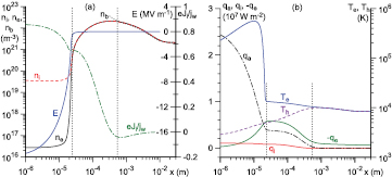
Figure 3. Distributions of parameters in the near-cathode layer. Unified modelling.  A m−2.
Download figure:
Standard image High-resolution image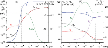
Figure 4. Distributions of parameters in the near-cathode layer. Unified modelling.  A m−2.
Download figure:
Standard image High-resolution imageThe quantity  in figures 3(a) and 4(a) has the meaning of fraction of electric current transported by the ions. In the bulk plasma, this fraction is low, as should have been expected. On the cathode surface, this fraction attains a value of about 0.86 in the case
  A m−2 and 0.22 for
  A m−2. The ion current is generated primarily in the ionization layer, as expected.
In the case  A m−2 (figure 4(b)), the electron temperature in the near-cathode layer does not change much. In contrast, the variation of Te is very large in the case
  A m−2 (figure 3(b)). However, the variation of Te in the ionization layer remains relatively small. This explains why the integral-balance evaluation of the average electron temperature in the ionization layer, employed in the model [29–31], is accurate over the whole range of jw shown in figure 1.
Neglecting variation of Te in the case  A m−2, one can assume that the density of plasma electrons in the sheath follows the Boltzmann distribution evaluated at the temperature Teil. Then one can write
  , where
  is the density of the ions (or the electrons) at the sheath edge, and the expression for jCD in equation (1) will coincide with the corresponding expression in the model [29–31]; see equation (A.7) of the appendix or equation (5) of [43]. This explains the good agreement in current density and energy flux transported by the fast plasma electrons ( jCD, qCD) seen in figures 1(b) and (c) for
  A m−2. For lower
  , Te in the sheath significantly exceeds Teil, and the electron density in the sheath significantly exceeds values given by the Boltzmann distribution evaluated at the temperature Teil. This explains why, for
  A m−2, jCD and qCD given by the unified modelling significantly exceed the values given by the model of the near-cathode layer [29–31], as seen in figures 1(b) and (c).
One can see in figures 3(b) and 4(b) that in the bulk plasma the energy fluxes of the heavy particles, qa and qi, are small compared to the electron energy flux, as should have been expected. The net energy transport is directed not from the bulk plasma into the near-cathode layer, but in the opposite direction, which is also expected [34]. qa and qi grow in the near-cathode layer.
Equation (11) of [13], which describes conservation of energy of heavy particles in the unified model, may be transformed to
where φ is electrostatic potential, Dea and Dei are binary diffusion coefficients, and n is the total number density of the plasma. The terms on the rhs of this equation account for, respectively, work of the electric field over the ions, energy gained by the ion species due to ionization, and the energy received by the atoms and ions in elastic collisions with the electrons. Integrating equation (4) from x to the outer boundary L of the calculation domain, one finds the integral balance of energy of heavy particles in the layer ![$[x,L]$](https://content.cld.iop.org/journals/0022-3727/49/21/215201/revision1/daa1d8fieqn036.gif) :
:


An example of the distribution of the terms on the rhs of equation (5) in the near-cathode layer is shown in figure 5. The energy flux at the outer boundary of the calculation domain is relatively small,  W m−2, and cannot be seen on the graph. As x decreases, qh increases, first due to energy transfer from electrons to the ions in ionizing and elastic collisions (Wion, Wei) and then due to work of the electric field over the ions (
 ). The energy Wea transferred from electrons to the atoms is small. Hence, the increase in qh in the near-cathode layer occurs due to the energy supplied to the ions. Part of this energy is subsequently transferred to the atoms through ion–atom collisions. The latter process affects the distribution of the energy between the ions and the atoms, but does not affect the total energy of the heavy particles. This explains the very good agreement between values of qhw given by the two models seen in figure 1(c).
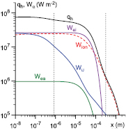
Figure 5. Energy balance of the heavy-particle gas in the near-cathode region. Unified modelling,  A m−2.
Download figure:
Standard image High-resolution imageNote that the use of a single heavy-particle temperature in the unified modelling implies that thermal equilibrium between the ions and the atoms is established instantaneously. In reality, the (translational) energy is transferred from the ions to the atoms over distances of the order of the mean free path for collisions between ions and atoms,  . Let us consider as an example a high-current arc in atmospheric-pressure
  and assume that
  K and
K and  K in the near-cathode plasma. An estimate for these conditions gives
  μm. It follows from figure 5 that most of the energy that the ions receive from the electric field in the near-cathode layer cannot be transferred to the atoms. Thus, values of the ion energy flux density qiw, predicted by the unified modelling and the model of nonlinear surface heating, should be considered as, respectively, lower and upper estimates.
The model of nonlinear surface heating, as it is used in this work, comprises the model of the near-cathode layer [29–31], based on the assumption that the ions cross the near-cathode space-charge sheath without collisions. If the pressure of plasma-producing gas is much higher than atmospheric, the latter assumption becomes unrealistic. However, the model of nonlinear surface heating comprising the model of the near-cathode layer [29–31] may still remain useful. As an example, a comparison similar to that of figure 1 is shown in figure 6 for an arc burning in mercury vapor at 200 bar, which is a representative plasma-producing gas in projection lamps. (The dependences  computed by means of the two models coincide to the accuracy of the graph, so the corresponding curves in figure 6(c) overlap.) There is a significant discrepancy in the current density and energy flux transported by the fast plasma electrons (jCD, qCD), but all the other quantities are close to each other.

Figure 6. Parameters of the cathodic part of the arc computed with the use of the unified modelling (solid) and the model of nonlinear surface heating (dotted). Arc in Hg plasma at 200 bar.
Download figure:
Standard image High-resolution image4. Comparing results from the NLTE-sheath modelling approach and the model of nonlinear surface heating
Let us consider a free-burning arc in atmospheric-pressure argon. The cathode is a tungsten rod of radius 1 mm and height 12 mm, with a hemispherical tip. The anode is planar and made of copper. A numerical investigation of this arc by means of the 2T-ionization layer-sheath approach was performed in [34, 35] and by means of the NLTE-sheath approach in [28]. In particular, the computed arc voltage was in good agreement with the experimental data [45]. In this work, we do not consider characteristics of the arc as a whole and will rather focus on comparison of characteristics of the cathodic part of the arc given by the two approaches.
The NLTE-sheath approach is used as described in [28]. The model of nonlinear surface heating, to which the 2T-ionization layer-sheath approach is reduced, is used as described in [34, 35]; the only difference from the previous section is that the nonlinear boundary-value heat conduction problem in the cathode body is solved by means of the steady-state solver of COMSOL Multiphysics instead of a home-made FORTRAN code implemented in the internet tool [44].
Distributions along the cathode surface of the surface temperature and the density of electric current to the surface, computed by means of the NLTE-sheath approach for the arc current I = 100 A and three different values of the interelectrode distance (7, 10 and 13 mm), are plotted in figure 7 as solid lines. (The distance l is measured from the centre of the front surface of the cathode along the generatrix of the cathode surface.) The lines corresponding to the different interelectrode distances coincide. This is a manifestation of plasma–cathode interaction being to the first approximation independent of processes in the arc bulk, which constitutes the basis of the model of nonlinear surface heating as discussed in section 2.2.1. The results given by the model of nonlinear surface heating (dotted lines in figure 7) are in excellent agreement with those given by the NLTE-sheath approach.

Figure 7. Distribution of cathode surface temperature and current density computed with the use of the NLTE-sheath approach for different values of the interelectrode distance (solid) and the model of nonlinear surface heating (dotted). I = 100 A.
Download figure:
Standard image High-resolution imageA comparison of distributions along the cathode surface of characteristics of the cathodic part of the discharge, computed with the use of the two models for three values of the arc current I = 60, 100 and 200 A, is shown in figure 8. The distributions computed by means of the NLTE-sheath model for different interelectrode distances (7, 10 and 13 mm) are very close to each other; we note for definiteness that the data shown in figure 8 refer to the interelectrode distance of 10 mm.

Figure 8. Distribution of parameters of the cathodic part of the arc computed with the use of the NLTE-sheath approach (solid) and the model of nonlinear surface heating (dotted or dashed).
Download figure:
Standard image High-resolution image
In most cases, the agreement is good, especially at the front surface of the cathode tip ( mm), which is the main part of the arc attachment. Distributions of the surface temperature and density of electric current to the cathode surface (figure 8(a)) agree quite well, similarly to those in figure 7. Distributions of the energy flux to the cathode surface (figure 8(b)) are in good agreement for I = 60 A, but deviate for 100 A and especially for 200 A. Note that one could think that this deviation is a consequence of the Joule effect inside the cathode, which was taken into account in the NLTE-sheath approach but not in the realization of the model of nonlinear surface heating being employed; however, this has been disproved by additional simulations performed by means of the model of nonlinear heating with account of the Joule effect as in [46].
Values of the density of ion current to the cathode surface (figure 8(b)) given by the NLTE-sheath approach are close to those given by the model of nonlinear surface heating at the centre of the front surface of the cathode, but decrease faster with increasing l. Values of the sheath voltage (figure 8(c)) given by the two models are close to each other at the centre of the front surface of the cathode. As l increases, the values given by the NLTE-sheath model increase weakly, while those given by the model of nonlinear surface heating decrease weakly; however, the difference between the two is not very significant.
In the framework of the NLTE-sheath model, Te in figure 8(c) represents the electron temperature on the plasma side of the interface describing the sheath. In the nonlinear surface model, Te has the meaning of the average electron temperature in the ionization layer as in section 1. The two distributions are not very different, except for the maxima occurring in the range  in the NLTE-sheath model, which, however, have little relevance since the current density at these l values is already quite small.
5. Summary and concluding remarks
Three approaches to describing separation of charges in near-cathode regions of high-pressure arc discharges are considered. The most straightforward one is the unified modelling, which does not rely on a priori division of the interelectrode gap into quasi-neutral plasma and space-charge sheaths.
The second approach, which may be called the NLTE-sheath approach, is based on separate descriptions of the bulk quasi-neutral plasma and space-charge sheaths formed near solid surfaces (electrodes and insulators). The description of the bulk plasma is fully non-equilibrium, i.e. it does not rely on assumptions of thermal ( ) or ionization equilibrium. The appropriate description of space-charge sheaths is developed in the appendix.
The third approach employs separate descriptions of the bulk plasma, where deviations between Te and Th are taken into account but deviations from ionization equilibrium are not, of the ionization layer and of the near-cathode space-charge sheath. This approach may be called the 2T-ionization layer-sheath approach. Since processes in the bulk have little effect over the cathodic part of the arc, calculation of the cathodic part (the cathode, the sheath and the ionization layer) is decoupled from calculation of the bulk plasma in the framework of this approach. The reduced version, in which only the cathodic part is simulated, is sometimes referred to as the nonlinear surface heating model.
Since the unified modelling has been performed until now only in 1D cases while the NLTE-sheath approach has been realized only for the axially symmetric case, we cannot compare all three approaches at once. Results given by the unified modelling are compared with those given by the model of nonlinear surface heating for the simple 1D test case of a rod cathode with thermally and electrically insulated lateral surface. Results given by the NLTE-sheath approach are compared with those given by the model of nonlinear surface heating for the (axially symmetric) test case of a free-burning atmospheric-pressure argon arc with a rod cathode with a hemispherical tip. It is found that the results given by different models are generally in good agreement, and in some cases the agreement is even surprisingly good.
On one hand, this finding is consistent with estimates given in the appendix (see also section 1 of [28]), which indicate that for typical high-pressure arcs the Debye length is much smaller than the ionization length, which is in turn much smaller than characteristic arc dimensions; hence the necessary conditions of applicability of both the NLTE-sheath and 2T-ionization layer-sheath approaches are fulfilled. On the other hand, the above finding shows that the predicted integral characteristics of the arc-cathode interaction are not strongly affected by details of the model (such as the ion motion in the sheath being collision-free or collision-dominated, variability of Te and Th in the near-cathode layer, distribution of the heavy-particle energy flux from the plasma to the cathode surface between the atoms and the ions) provided that the basic physics is right.
The unified modelling approach is at present prohibitively intensive computationally in situations of practical interest that require multidimensional simulations. If the main objective is to simulate the cathodic part rather than the arc as a whole, then it seems natural to employ the model of nonlinear surface heating, which is the simplest one and is ready for use for a wide range of plasma-producing gases and cathode materials (e.g. [44]). This model is a natural first step also in simulations of the arc as a whole, which can be performed by means of either the NLTE-sheath approach or the 2T-ionization layer-sheath approach. The former is the method of choice in cases where deviations from ionization equilibrium occurring in the vicinity of the anode and in the arc fringes are of interest. The current density distribution along the cathode surface, given by the model of nonlinear surface heating, may be used as an initial approximation in this approach, which will contribute to the solution's stability [28].
The 2T-ionization layer-sheath approach may be used in cases where deviations from ionization equilibrium occurring in the vicinity of anode and in the arc fringes are not of primary interest. The solution given by the model of nonlinear surface heating provides boundary conditions at the cathode surface for the bulk plasma equations in this approach.
Up to now, both the NLTE-sheath and the 2T-ionization layer-sheath approaches have been applied only to cases where current transfer to the cathode occurs in the diffuse mode. It will be very interesting to extend the modelling to spot modes. Since the model of nonlinear surface heating allows a routine calculation of spot modes, calculation of corresponding states of the arc bulk is straightforward in the 2T-ionization layer-sheath approach and seems to be feasible in the NLTE-sheath approach. Another effect to be treated in the future is motion of the molten metal in the cathode, which is especially important at high currents.
Acknowledgments
The work at Universidade da Madeira was supported by FCT—Fundação para a Ciência e a Tecnologia—of Portugal through the projects PTDC/FIS-PLA/2708/2012 and Pest-OE/UID/FIS/50010/2013. The work at INP Greifswald e.V. was supported in part by the DFG (German Science Foundation) under grant UH106/11-1. The collaboration between INP Greifswald e.V. and Universidade da Madeira has been supported in part by funding from the European Union Seventh Framework Programme under grant No. 316216.
Appendix.: Boundary conditions describing positive and negative space-charge sheaths in non-equilibrium models of arc discharges
The calculation domain in fully non-equilibrium models of arc discharges includes the quasi-neutral plasma and eventually the adjacent solid bodies (electrodes and insulators), separated by interfaces describing the space-charge sheaths. The boundary conditions at these interfaces are formulated in what follows.
The electrostatic potential is discontinuous at the interface:

Here Ush has the meaning of the sheath voltage, which varies along the solid surface and has to be found as part of the solution, the upper indices 'pl' and 's' denote values on the quasi-neutral plasma side of the interface and on the side of the solid, respectively. The electric current is continuous at the interface:
where  and
and  are the normal components of the densities of electric current from the quasi-neutral plasma to the interface and from the interface into the solid. (If the solid represents a dielectric, then
  and this boundary condition implies that temporal variations of surface charge on the dielectric are neglected.) In the following, let us replace both designations
  and
and  with jw. Again, jw varies along the surface and has to be found as part of the solution. One can write

Here  and
and  designate normal components of the number densities of, respectively, the ion and electron fluxes coming to the interface from the quasi-neutral plasma, which are governed by the hydrodynamic (diffusion) equations describing the plasma.
Let us consider as an example a high-current arc in atmospheric-pressure  and assume that
  K and
K and  K in the near-cathode plasma. An estimate for these conditions gives
  μm for the Debye length and
  μm for the ionization length. Since
  , ionization and recombination are negligible inside the sheath. Hence, the densities of ion and electron fluxes across the sheath are constant and equal to
  and
and  , respectively.
If the solid represents a dielectric,  , or an electrode operating as a cathode,
  , then
  . If the solid represents an electrode operating as an anode,
  , then Ush may be either negative or positive. Note that in terms of the so-called near-anode voltage (see, e.g. definition in [14])
  corresponds to positive near-anode voltage and vice versa.
It is natural to neglect variations of the heavy-particle temperature inside the sheath, which gives a boundary condition

The energy flux is discontinuous at the interface and the corresponding boundary condition is represented by the equation of integral balance of energy:
where  and
and  are normal components of the energy fluxes coming, respectively, from the quasi-neutral plasma to the interface and from the interface into the solid, Af is the work function of the electrode material, Ai is the ionization energy and
  is the net density of energy flux removed from the solid surface by radiation. Note that
  comprises the heat fluxes caused by heat conduction and by the effect inverse to thermal diffusion, the enthalpy transport by the diffusion fluxes, but not transport of production enthalpies and radiation. The term
  on the rhs of equation (A.5) represents power deposited into the sheath by the arc power supply,
  is cooling of the electrode surface due to passage of the electrons from metal into the plasma, and
  is the power deposited at the solid surface due to neutralization of the ions coming from the plasma.
It may be convenient for numerical implementation to introduce a new variable, which equals the temperature in the solids and the heavy-particle temperature in the bulk plasma, and to treat the equation of energy of heavy particles in the quasi-neutral plasma jointly with the equations of heat conduction inside the solids. In this connection, it may be convenient to transform the boundary condition (A.5) with the use of the relation  , where
  and
and  are normal components of energy fluxes transported from the quasi-neutral plasma to the interface by heavy particles and electrons, respectively, and to rewrite this boundary condition as

The form of the rest of the boundary conditions depends on the sign of the sheath voltage. Let us consider first the case of a positive sheath,  . In this case, the electrons from the quasi-neutral plasma are repelled by the sheath electric field and follow in the sheath the Boltzmann distribution in space with a temperature equal to
  , the electron temperature in the quasi-neutral plasma estimated at the interface. The density of the flux of plasma electrons counterdiffusing to the surface against the retarding electric field is given by the usual expression
If the solid represents an electrode and its surface is hot enough, there is a second group of electrons in the sheath: those emitted by the electrode surface. Therefore, in the general case one can write

where jem is the density of electron emission current.
Integral balance of electron energy in the sheath yields
The first term on the lhs represents the density of flux of energy removed from the solid surface by the emitted electrons, evaluated under the conventional approximation of the velocity distribution of the emitted electrons being the half-Maxwellian function with the surface temperature.  is the flux of energy delivered to the surface by the plasma electrons, so the first and second terms jointly represent the net electron energy flux from the solid to the sheath. The third and fourth terms represent, respectively, the electron energy flux from the quasi-neutral plasma to the sheath and the work of the electric field over the electrons inside the sheath.
Lowering of the work function due to the presence of an electric field (the Schottky effect) is appreciable for arc electrodes if  . It is logical to assume in such conditions that the energy gained by an emitted electron on crossing the space-charge sheath is equal to
  , where
  is the Schottky correction. The energy gained (lost) by a singly charged ion (plasma electron) moving to the electrode is the same. Therefore, in the following we will assume that the factor Ush in the last term on the lhs of equation (A.9) is replaced by
  . Note that there is no need for such replacement in equation (A.5) or (A.6), where Ush appears in the combination
  .
.
Relaxation of the two-group electron distribution function in the sheath to the Maxwellian distribution in the bulk plasma occurs on the length scale  , the mean free path for electron–electron collisions. Under the above-mentioned conditions of a high-current arc in atmospheric-pressure
  ,
,  μm. Hence, another zone distinguished by specific physics is relevant: the layer of electron relaxation, which is much thicker than the sheath but much thinner than the ionization length. The fact that equations (A.8) and (A.9) involve electron particle and energy fluxes to the interface,
  and
and  , which are governed by the hydrodynamic (diffusion) equations, implies that the layer of electron relaxation is implicitly included in the interface jointly with the space-charge sheath.
The number density of charged particles in the sheath is much smaller than that in the quasi-neutral plasma, so the boundary condition for the distribution of the charged particles in the quasi-neutral plasma to be applied at the interface could be written simply as  . However, we consider the case where the sheath is collision-free for ions, and in this case the use of this boundary condition would require one to expressly treat the Knudsen layer, i.e. a region of quasi-neutral plasma that is adjacent to the sheath and has a thickness of the order of the mean free path for ion–neutral collisions, where the ions are accelerated up to the Bohm speed
  (in other words, the Knudsen layer plays the role of a presheath). In order to avoid such treatment, one can assume that the acceleration of the ions up to the Bohm speed may be described to a reasonable accuracy by the hydrodynamic (diffusion) equations and can use at the interface the boundary condition (e.g. [29])

The electric field at the electrode surface needed for evaluation of the Schottky correction may be estimated with the use of equation (10) of [29] (which was derived for the case where the sheath is collision-free for ions). Then relations (A.1) and (A.2); (A.4) and (A.5); (A.9); and (A.10) represent a complete set of boundary conditions at the interface for the differential equations of, respectively, current continuity in the quasi-neutral plasma and the electrode; heavy-particle energy in the plasma and heat conduction in the solid; electron energy in the plasma; and ambipolar diffusion in the plasma. Since the sheath voltage Ush remains indeterminate in this reasoning, an additional relationship is needed: equation (A.8).
Let us proceed to the case of a negative sheath,  . In this case, the ions in the sheath follow the Boltzmann distribution with a temperature
  and one can write, similarly to equation (A.7),
Most of the electrons eventually emitted by the solid cannot overcome the potential barrier in the sheath and immediately return to the surface. Therefore, electric current transported by the emitted electrons can be neglected. In particular, one should drop the term involving jem and set  in equation (A.9) (of course, there is no need to replace Ush with
  in this equation in the case
  ).
).
The electrons from the quasi-neutral plasma enter the sheath with the electron Bohm speed  ; see discussion in [47]. Therefore, equation (A.10) is replaced with

Equation (A.9) with the above-described changes and equation (A.12) represent boundary conditions at the interface for the differential equations of electron energy and ambipolar diffusion in the plasma in the case  . The additional relationship is supplied by equation (A.11).
Note that in finite-element codes such as COMSOL Multiphysics the Dirichlet boundary condition for the ambipolar diffusion equation may be less favorable from the point of view of numerical stability than the Neumann condition. In this connection, it may be appropriate to use as a boundary condition for the ambipolar diffusion equation in the plasma not equation (A.12) as it is, but rather a combination of this equation with (A.11):