

Abstract
The Time Transfer by Laser Experiment (T2L2) on the Jason 2 satellite is a mission allowing remote clocks synchronization at the picosecond level. It is based on laser ranging technologies, with a laser station network on the ground and a dedicated instrument on board the satellite. It was launched in June 2008 and has been working continuously since then. T2L2 performances are very promising for time and frequency metrology and also for fundamental physics. The scientific objectives of the whole experiment rely on a rigorous uncertainty budget. This is governed by the characteristics of the space instrument and the laser stations network, the post treatment done on the ground, and also the process used to calibrate the laser stations. The uncertainty budget demonstrates that T2L2 is able to perform common-view time transfers between remote sites with an expanded uncertainty better than 140 ps (coverage factor = 2).
Export citation and abstract BibTeX RIS

Content from this work may be used under the terms of the Creative Commons Attribution 3.0 licence. Any further distribution of this work must maintain attribution to the author(s) and the title of the work, journal citation and DOI.
1. Introduction
T2L2 [1–3] is a two-way time transfer mission based on the timing of optical pulses emitted by a network of laser stations and detected by a dedicated space instrument. It allows for the synchronization of remote clocks with a time stability in the range of a few picoseconds over hundreds of seconds. After four unsuccessful proposals, in 2005 T2L2 was accepted as a passenger instrument on the Jason 2 altimetry satellite. It was launched in June 2008 and has been working without any major interruption since that time. It was put in place by a Delta launcher at an altitude of 1336 km and an inclination of 66°.
The elementary T2L2 link is a ground-space time transfer between a given laser station and the space instrument. For a time comparison between two laser stations, several ground to space elementary links are used for each ground station. To realize the ground-space transfer, the laser station emits asynchronous short light pulses towards the satellite. A reflector array on board the satellite returns some of the light pulses to the ground station. The epoch of the laser emission tE and the epoch of the reception tR are measured according to the ground station's timescale. The T2L2 payload records the arrival time tB of laser pulses according to the timescale of the space clock. Schematically, the time offset ΔAS between a ground clock A and the space clock S is computed for each laser pulse, where the difference between the start and the arrival epochs is shifted by the time of flight divided by two. ΔAS is given by:

where CAS is a correction term that takes into account instrumental calibrations, atmospheric phenomena, speed aberrations and relativistic effects. The T2L2 data are very interesting for both time and frequency metrology and for fundamental physics. For instance, T2L2 is able to calibrate and validate the best available microwave time transfer techniques [4, 5] and will be able to compare the time transfer systems embedded on the new mission ACES (Atomic Clock Ensemble in Space) that will be launched on the ISS (International Space Station) in 2017 [6]. The possibilities given by an accurate time transfer between remote clocks is also of interest for the search for a potential anisotropy of the speed of light [7] or for the validation of one-way laser ranging for some future tests involving solar orbit [8, 9]. All these scientific objectives rely on a rigorous uncertainty budget for the whole experiment that is governed by the characteristics of both the space instrument and the laser stations network, as well as the calibration process used on the ground.
In section 2 we give a brief description of the whole instrumentation (ground and space) involved in a T2L2 time transfer. In sections 3 and 4, we describe the time transfer equations for both the ground to space and the ground to ground links. Then, from these equations, we give in section 5 the uncertainty budget of a typical T2L2 time transfer.
2. Instrumentation
The ground-level part of the T2L2 time transfer is based on the international laser station network [10]. This gathers data from more than 40 laser ranging stations over the world and is driven by the International Laser Ranging Service (ILRS) which provides global satellite and lunar laser ranging data to support research in many scientific domains such as geodesy, geophysics, lunar science, and fundamental physics.
A typical laser station is composed of the following elements (figure 1):
- A clock to give the station a frequency reference (5 or 10 MHz). From this frequency reference a numerical divider generates a one pulse per second signal (PPS) for timescale purposes. For laser ranging, this clock is used to measure the time interval between the start and the return; for T2L2, it is the clock which has to be synchronized.
- A neodymium YAG doubled laser to generate pulses at a rate of between 10 Hz and 2 kHz. The wavelength is usually 532 nm and the full width at half maximum is between 50 ps to 200 ps.
- A telescope to transmit and receive laser pulses. Some stations have the same telescope for both transmission and reception, while others have two distinct apertures.
- A start detector to generate the start reference at the output of the laser.
- A return detector to detect pulses which have been reflected by the satellite.
- An event timer that has two independent channels to time tag the electrical pulses of both start tE and return tR detectors. The time setting of the event timer is carried out at the first initialization with the PPS signal delivered by the clock of the time and frequency standard laboratory.

Figure 1. Simplified scheme of a typical laser station. Time and frequency equipments are generally located in a dedicated laboratory.
Download figure:
Standard image High-resolution imageThe T2L2 space equipment is an instrument able to time with picosecond resolution the arrival of all laser pulses arriving from the laser stations. It comprises a photo-detection device and an event timer. This equipment is associated with an ultra-stable quartz oscillator used as the T2L2 onboard clock and a retro-reflector array. These two components are used by T2L2 but are not integral to T2L2: the oscillator is the frequency reference of the DORIS System [11] and the LRA is used for satellite laser ranging (figure 2).

Figure 2. T2L2 Global architecture with unit A outside the satellite oriented toward the earth direction and unit B inside the payload. The DORIS USO and the LRA equipments are not a T2L2 subassembly.
Download figure:
Standard image High-resolution imageThe photo detection device includes two avalanche photodiode photo detectors. One of them works in a nonlinear mode for time tagging purposes [12], the other works in a linear mode to trig the non linear detector and to measure the received laser energy. The most important function of the nonlinear photo detector is to generate an electrical pulse from a very low level of light. The propagation delay inside the photo detector depends on the photon number. To avoid the temporal noise that would be introduced by an uncontrolled energy variation of the laser pulse (atmosphere, pointing error, laser variation and so on) this internal delay is compensated for. This is achieved with the linear photo detector giving the energy received. This energy together with the arrival time is recorded in real time onboard and downloaded to ground every two hours. The compensation for the internal delay of the detector is achieved by means of a post treatment process [13, 18]. The laser energy received at the satellite plane is sent to the photo-detectors through two distinct optics assemblies. This allows the geometry to fit the field of view of the instrument, the photon number to be adjusted and the spectral band width to be fixed. All this instrumentation is divided on the Jason 2 payload in two units A and B.
3. Ground to space time transfer
The offset ΔAS between a ground clock A and the space clock S is given by:

where tE and tR are respectively the emission and reception epochs of laser pulses at the laser station, tB the reception epoch on board, CSag a correction due to the speed aberration, CRel a term illustrating the relativistic frequency shift [13], CAtm an atmospheric correction and CICal (internal calibration), CECal (external calibration) are two calibration terms to obtain respectively the time of flight between the reference point of the station and the satellite and the epoch of laser events at the reference point of the laser station. In order to minimize the noise associated with the measurement of the time of flight (computed from tR and tE in equation (2)), some reception epochs tR' are computed from an interpolation calculated on the actual measure tR. This process also allows the use of laser events which have been detected on board the satellite but not on the ground. It is especially important for laser stations using a single photon mode detector (where the detection probability is in the range of 10%). In this case, the number of echoes detected by the laser station may be several times lower than the number of detected events on board.
CSag is associated with the computation of the time coordinates to take into account the propagation of laser pulses. CSag is given by:
It is computed from the coordinates x from the satellite and X from the station for each emission epoch.
CRel is associated with the transformation from the proper time of the onboard clock to coordinate time. It is a frequency shift of the space oscillator integrated as a function of time. CRel is given by:
where GME is the geocentric gravitational constant. This relativistic frequency shift includes a constant term, which can be neglected in the ground to ground time transfer, and also a periodic term. The amplitude of the periodic frequency shift integrated over an orbit is in the range of 100 ps.
CAtm is a correction reflecting the optical path difference introduced by the atmosphere between the uplink and the downlink. The worst case occurs with a laser station located near the equator and an observation of the satellite at a very low elevation angle (typically 5°). In that case, the time delay for the one-way link is roughly 40 ns and the time correction CAtm between the uplink and the downlink is 1.5 ps.
CICal is obtained from epochs measured by means of laser pulses sent to the reception chain of the station by means of a calibration corner cube located in the laser beam (figure 1) at a set distance dcc from the spatial reference of the station (cross axes of the telescope mount). This is measured at the same time as the acquisition of echoes on the satellite from the mean value of an ensemble of NICal epoch differences:

 being the reception epochs of laser pulses coming from the retro reflector and δcc a correction term taking into account the distance between the reference corner cube and the cross axis of the telescope.
CECal is measured by means of a dedicated calibration process. Laser stations are basically designed to measure the time difference between a start and a stop with an accuracy of the start pulse of typically 100 ns. In order to obtain the picosecond accuracy required for T2L2, laser stations are carefully calibrated with a dedicated calibration station. This calibration is based on a set of simultaneous measurements made of the habitual chronometry of the laser station and the dedicated calibration station. It permits measurement of the delay between the optical pulse at the cross axis of the telescope and the electrical reference coming from a given output of the PPS distribution unit of the time and frequency laboratory. The calibration station gathers all the metrology required to perform that measurement in a unique piece of equipment: this comprises a SigmaTime STX301 sub-picosecond event timer (figure 3), an optical module to grab laser pulses from the laser station and an optical fiber (figure 4). The event timer has two independent channels connected to optical and electrical inputs. The optical module comprises a collimation optic connected to a 50 m mono mode optical fiber (532 nm).

Figure 3. STX301-002R SigmaTime sub-picosecond event timer designed for the calibration of laser stations.
Download figure:
Standard image High-resolution image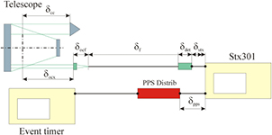
Figure 4. Definition of the propagation term through the telescope to the PPS distribution unit.
Download figure:
Standard image High-resolution imageCharacteristics of the calibration station are given in table 1.
Table 1. Main characteristics of the T2L2 calibration station.
| Parameters | Values |
|---|---|
| Time stability @ 1000s (TDev) | < 20 fs |
| Linearity | 0.3 ps RMS |
| Standard deviation | 700 fs RMS |
| Optical input bandwidth | DC − 20 GHz |
| Electrical input bandwidth | DC − 8 GHz |
The term CECal is computed from the mean value of an ensemble of NECal measurements. The time equation that allows the accurate time-tagging of laser pulses may be written as:
where  is the emission epoch measured by the calibration station, δocx the free space delay propagation between the station reference and the optical input of the calibration station, and δprg the global internal propagation inside the calibration station. δPPS is the delay in the PPS cable, δ f the delay in the optical fiber, δocf the delay of the collimation optic, δdet the propagation constant induced by the optical to electrical conversion inside the detector [14] and δstx the delay in the cable between the detector and the event timer. By using the same calibration station to calibrate the different laser stations, the delays
  in equation (6) do not need to be known accurately. It must be emphasized that in this case, the calibration becomes relative since we do not know the real emission epoch of laser pulses. It is perfectly well suited for an accurate comparison of T2L2 with any other time transfer techniques from the temporal reference of each laboratory but it would become a difficulty if it was necessary to compare a given technique directly from the laser pulses.
The term  is determined from the time setting of the SigmaTime STX301 event timer and from a simultaneous acquisition of an ensemble of laser pulses from the laser station and the calibration station. The time setting process allows the acquisition of measurements directly referenced to the time reference of the laboratory. It is carried out using a preliminary measurement of the PPS reference signal of the laboratory. The PPS threshold level is always set at 1 V. The time stability over one day of a typical PPS signal is in the range of 20 ps. To minimize the uncertainty of that time setting process, the PPS measurement is carried out over a set of NTS = 30 PPS events. At the same time, a scan of that PPS signal is also performed by the event timer to determine the actual shape of the PPS signal. For that measurement, the event timer is used as an oscilloscope. It generates a graph where the abscissa axis is time and the ordinate axis is voltage. One channel of the event timer is used as the trigger for the time reference and the other is used to measure the signal. Figure 5 is an example of such a scan measured by the STX301 event timer.

Figure 5. PPS Scan measured by the Sigma time STX301 event timer.
Download figure:
Standard image High-resolution image4. Ground to ground time transfer
The ground to space time transfer computed from equation (2) can be used directly on individual echoes. It allows monitoring of the time transfer with the optimum temporal resolution (the typical time interval between consecutive laser event is roughly 1 s). The same computation, integrated over a few tens of seconds or over an entire satellite pass in order to minimize the white noise of the time transfer, is also of interest.
Ground to ground time transfer can be realized in either common-view or non-common-view mode. In the first case, the satellite is seen during a common period while in the other, the satellite is observed alternatively. For common-view, the maximum distance to the ground is roughly 6000 km.
Ground to ground time transfer depends very significantly on the visibility of the satellite. In common-view mode, the space oscillator is only solicited over the time interval of laser pulses (typically between 0.1 s to a few seconds). Over a longer period, noise is common for both stations and the difference vanishes. In the non–common-view mode, the noise of the space oscillator has to be considered over the time interval during which the satellite is not visible, and the noise of the space oscillator can become the main source of noise. That noise can be significantly reduced with a correction model Cosc taking into account parameters such as temperature, radiation or time. Up to now this model has not been operational. In what follows, we will only discuss ground to ground time transfer in common-view.
A ground to ground time transfer ΔAB between two ground clocks A and B in common-view is computed from the difference between the individual time transfers xAS and xBS individually acquired by the stations. One has:

Since the laser emissions for each station are not synchronous, data from the ground to space time transfer of each station are first interpolated on the full seconds in the timescale of the satellite. The final time transfer xAB is computed from the individual time transfer interpolated on the common full seconds.
5. Uncertainty budget
Considering that the terms of equation (2) are independent, the combined uncertainty of a time transfer  between a ground clock and the space clock may be written as:
The combined uncertainty of a ground to ground time transfer in common view is given by:

Each uncertainty term in equations (8) and (9) is evaluated from other parameters. Some of them are evaluated using a statistical analysis of a series of observations (Type A) and others are arrived at using other methods (Type B).
Each uncertainty term should be determined on the basis of the precise experimental setup for a given link between two laser stations. In order to give a more general uncertainty budget, we will consider in the following a typical setup reflecting the characteristics of a large number of laser stations well suited for time transfer. The main uncertainties of such a station are summarized in table 2.
Table 2. Typical laser station.
| Sub-system | Characteristics | Type | u/ps | Comments |
|---|---|---|---|---|
| Start detector | InGaAs pin photodiode, Band Width = 3 GHz Diameter 30 µm | A | 5 | Standard deviation obtained at constant threshold in a saturated mode [1, 22] |
| Return detector | Avalanche silicon photodiode, Geiger mode Diameter 200 µm | A | 50 | Standard deviation made in a single photon mode over the whole aperture [12, 14, 15] |
| Nd:YAG Laser | Active and passive mode locked laser, Flash pumped λ = 532 nm, 10 Hz, E = 50 mJ, FWHM = 100 ps | B | 25 | Uncertainty of the laser pulse width at half maximum (long and short term pulse variations)4 |
| Event timer | 2 independent channels, External frequency reference 10 MHz, Internal frequency PLL 200 MHz, resolution 1 ps | A | 5 | Standard deviation based on a perfect frequency reference [16, 21] |
| PPS Generator | Numerical division of a frequency source, 2.5 Vpp | A | 20 | Standard deviation of the output pulses as compared to the frequency reference [32] |
| TF lab to Laser Station cable | L < 100 m, Thermal <± 5 °C, <0.1 psK−1 m−1 | B | 30 | Uncertainty introduced by delay variations (thermal, radius, aging)5 |
| Ref. Corner cube | Simple corner cube, localization ±1 mm | B | 4 | Uncertainty introduced by the geometrical measurement between the corner cube and the spatial reference of the station6 |
The final combined uncertainty depends also on the quantity of data acquired. Of this data, the number of laser events emitted NE, echoes acquired NR and events recorded on board NB are especially important for the final uncertainty budget. The technical specifications of the laser station, together with observation conditions, of course have a strong influence on the outcome. For the sake of simplicity, these numbers are chosen to correspond to data acquired after a complete pass of the satellite above a ground station when observation conditions are difficult, with minimum on board events NB equal to 200. For the MeO laser station, this requirement represents roughly 90% of recorded passes. This value ensures also a satisfactory signal to noise ratio. The number of measurements for the internal and external calibration process and time setting is selected so that there is a negligible uncertainty associated with the mean value of each of those terms. Table 3 gives the values for all these measurements.
Table 3. Number of data considered for the uncertainty budget.
| Number | Value |
|---|---|
| Emission NE | 1000 |
| Reception NR | 300 |
| On board NB | 200 |
| PPS for time setting NTS | 30 |
| Event of internal calib. NIC | 250 |
| Event for external calib. NEC | 500 |
5.1. Instrumental uncertainties u(tE), u(tR), u(tB), u(CICal), u(CECal)
Regardless of the atmospheric correction CAtm illustrating the difference between the up-link and the down-link, atmosphere has a significant role on the measurement of epoch tB and tR [17]. The air turbulence generates fluctuations of refractive index along the beam path which randomly modify the propagation delay. The turbulence can be characterized by the outer scale parameter Lo (size of the largest turbulent eddy), the inner scale parameter Li (size of the smallest eddy) and refractive index structure constant Cn (strength of turbulence). Up to now, the theoretical model of the atmospheric fluctuation does not accurately reflect the actual fluctuations measured by laser ranging. The most conservative measured value that can be used in the uncertainties of the two way laser ranging is 3 mm RMS [18]. This value implies an uncertainty on the up-link (tB) of 5 ps (1.5 mm) and on the total link (tR) of 10 ps (3 mm).
Tables 4–8 give an evaluation of the combined uncertainty of the whole instrumentation of the T2L2 Time transfer [19–22]. Each parameter u(tE), u(tR), u(tB), u(CICal) and u(CECal) is a combined uncertainty computed from the quadratic sum of other uncertainties depending on the instrumentation [23–25]. Tables 7 and 8 are divided in three sub-sections separated by double lines. The first sub-section shows uncertainties which are not specific to the calibration process: the instrumentation of the laser station is used under exactly the same conditions as those for a classical observation. The next sub-section shows uncertainties corresponding to measurements of events which are specific to the calibration process. The final sub-section is specifically related to the calibration equipment.
Table 4. Emission epochs uncertainty u(tE).
| Uncertainty Source | Type | u/ps | Observation |
|---|---|---|---|
| Laser station start detector time walk versus Laser FWHM | B | 14 | Induced by the duration fluctuations of laser pulses7 [15] |
| Laser station start detector time walk versus laser energy | B | 3 | Induced by the energy variation of laser pulses7 [20] |
| Laser station cable delay: laser to detector | B | 6 | Uncertainty introduced by delay variations of the coaxial cable used for the signal propagation (thermal)5 |
| Laser station start detector internal noise | A | < 1 | Standard deviation obtained at constant threshold in a saturated mode. The uncertainty is computed on the mean value over NE [1, 22] |
| Frequency distrib. Between TF lab and laser station event timer | B | 30 | Uncertainty introduced by delay variations of the coaxial cable used for the distribution (thermal)5. The distribution is supposed free: no monitoring [32] |
| Time setting of the laser station event timer | A | 4 | Uncertainty computed on the over NTS8 [21] |
| Laser station event timer internal noise | A | < 1 | Uncertainty computed on the mean value over NE [21] |
| Combined uncertainty uc(tE) | A & B | 34 | Quadratic sum |
Table 5. Reception epochs uncertainty u(tR).
| Uncertainty source | Type | u/ps | Observation |
|---|---|---|---|
| Laser station return detector time walk versus laser FWHM | B | 3 | Induced by the duration fluctuations of laser pulses in a single photon detection mode7 [12] |
| Laser station return detector time walk versus laser energy | B | 5 | Included by the energy variation of laser pulses in a single photon detection mode7 [12, 22] |
| Laser station return detector time walk versus spot position | B | 7 | Speed aberration9 [12] |
| Laser station return detector internal noise | A | 3 | Uncertainty computed on the mean value over NR [12] |
| Laser station event timer internal noise | A | < 1 | The uncertainty is computed on the mean value over NR [21] |
| LRA signature | B | 13 | Attitude sensitivity10 [23, 24] |
| False detection | A | 4 | White noise [20] |
| Atmosphere (uplink + downlink) | A | 1 | Uncertainty computed on the mean value over NR [17] |
| Combined uncertainty uc(tR) | A & B | 17 | Quadratic sum |
Table 6. On board epochs uncertainty u(tB).
| Uncertainty source | Type | u/ps | Observation |
|---|---|---|---|
| Board detector time WALK versus laser FWHM | B | 14 | Induced by the duration fluctuations of laser pulses7 [22, 24] |
| Board detector time walk versus laser energy | B | 3 | Included by the energy variation of laser pulses7 [22, 24] |
| Board detector time walk versus incident angle | B | 3 | Optical path [24] |
| Board detector internal noise @ EMin | A | 5 | Uncertainty computed on the mean value over NB [24] |
| Board event timer internal noise | A | < 1 | Uncertainty computed on the mean value over NB [24] |
| LRA-detector geometry versus attitude | B | 3 | Attitude sensitivity11 [24] |
| False detection on board | A | 7 | White noise [20] |
| Atmosphere (uplink) | A | < 1 | Uncertainty computed on the mean value over NB [17] |
| Combined uncertainty uc(tB) | A & B | 16 | Quadratic sum |
Table 7. Internal calibration uncertainty u(CICal).
| Uncertainty source | Type | u/ps | Observation |
|---|---|---|---|
| Laser station start detector time walk versus laser FWHM | B | 14 | Induced by the duration fluctuations of laser pulses7 [15] |
| Laser station start detector time walk versus laser energy | B | 3 | Included by the energy variation of laser pulses7 [20] |
| Laser station start detector internal noise | A | < 1 | Standard deviation obtained at constant threshold in a saturated mode. Uncertainty computed on the mean value NIC [1, 22] |
| Laser station event timer internal noise | A | < 1 | Uncertainty computed on the mean value over NIC [21] |
| Laser station return detector time walk versus laser FWHM | B | 14 | Induced by the duration fluctuations of laser pulses in a single photon detection mode7 [12] |
| Laser station return detector time walk versus laser energy | B | 3 | Included by the energy variation of laser pulses in a single photon detection mode7 [12, 22] |
| Laser station return detector time walk versus spot position | B | 2 | Center uncertainty12 |
| Laser station return detector internal noise | A | 3 | Uncertainty computed on the mean value over NIC [12] |
| Laser station event timer internal noise | A | < 1 | Uncertainty computed on the mean value over NIC [21] |
| False detection | A | 1 | White noise |
| Corner cube position of the laser station | B | 4 | Free space delay6 |
| Combined uncertainty uc(CICal) | A & B | 21 | Quadratic sum |
Table 8. External calibration uncertainty u(CECal).
| Uncertainty source | Type | u/ps | Observation |
|---|---|---|---|
| Laser station start detector time walk versus laser FWHM | B | 14 | Induced by the duration fluctuations of laser pulses7 [15] |
| Laser station start detector time walk versus laser energy | B | 3 | Included by the energy variation of laser pulses7 [20] |
| Cable delay: laser to laser station start detector | B | 6 | Uncertainty introduced by delay variations of the coaxial cable used for the signal propagation (thermal)5 |
| Laser station start detector internal noise | A | < 1 | Standard deviation obtained at constant threshold in a saturated mode. Uncertainty computed on the mean value NE [1, 22] |
| Time distribution between TF lab and laser station event timer | A | 30 | Uncertainty introduced by delay variations of the coaxial cable used for the distribution (thermal)5. The distribution is supposed free: no monitoring [32] |
| Time setting of the laser station event timer | A | 4 | Uncertainty computed on the over NTS8 [21], |
| Laser station event timer internal noise | A | < 1 | Uncertainty computed on the mean value over NE [21] |
| Calibration station start detector time walk versus laser FWHM | B | 6 | Induced by the duration fluctuations of laser pulses13 [31] |
| Calibration station start detector time walk versus laser energy | B | 6 | Included by the energy variation of laser pulses13 [31] |
| Calibration station Start detector internal noise | A | < 1 | Uncertainty computed over the mean value over NEC13 |
| Time setting of the calibration station event timer | A | < 1 | Uncertainty computed over the mean value over NTS |
| Calibration station event timer internal noise | A | < 1 | Uncertainty computed over the mean value over NEC |
| Calibration station fiber delay: optic to detector | B | 9 | Thermal variation and aging [25] |
| Calibration station cable delay: ref. to event timer | B | 2 | BNC Connection14 |
| Calibration station ref. optic position | B | 4 | Free space delay15 |
| Combined uncertainty uc(CECal) | A & B | 36 | Quadratic sum |
5.2. Atmospheric uncertainty u(CAtm)
The amplitude of the atmospheric correction CAtm (difference between the up-link and the down-link) is 1.5 ps. The corresponding uncertainty u(Catm) of that correction is in the fs domain and can be set to 0 in the framework of this study.
5.3. Sagnac and relativity uncertainties u(CSag), u(CRel)
Both corrections CSag and CRel are calculated from the Jason 2 ephemerides and from the ITRF 2008 solution giving station coordinates [26, 27]. The coordinate uncertainties of both the laser station and the satellite are in the range of a few centimeters leading to negligible uncertainties for those terms (table 9) [13]:
Table 9. Sagnac and relativity uncertainties u(CSag), u(CRel).
| Uncertainty source | Type | u/ps | Observation |
|---|---|---|---|
| Combined uncertainty uc(CSag) | B | < 1 | Negligible |
| Combined uncertainty uc(CRel) | B | < 1 | Negligible |
5.4. Ground to space and ground to ground extension of uncertainties uE(ΔGS), uE(ΔGG)
The Ground to Space and the Ground to Ground uncertainties are computed from equations (8) and (9) with a number of acquired events given in table 3 (typically acquired during a single pass of the satellite). In the common-view mode, since the space oscillator is only solicited over the time interval between laser pulses, the uncertainty u(Cosc) may be neglected in comparison with the other noises.
In accordance with the recommendations given by the European Association of National Metrology Institutes (EURAMET), these uncertainties are computed for a coverage factor k = 2 [28]. The final uncertainty budget of the whole experience is summarized in table 10.
Table 10. Ground to space and ground to ground expanded uncertainties for a coverage factor = 2.
| Time transfer | Type | u/ps | Comments |
|---|---|---|---|
| Ground to space expanded uncertainty uE(ΔGS) | A & B | 98 | k = 2 |
| Ground to ground expanded uncertainty uE(ΔGG) | A & B | 138 | k = 2, Common view |
6. Validation
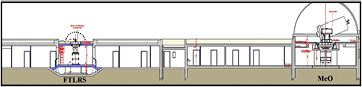
Observatoire de la Côte d'Azur (OCA) has two laser stations on the same site (MeO and FTLRS) that can be used together to realize a time transfer in a co-location configuration (figure 6). MeO is one of the biggest laser stations in the world with a 1.54 m telescope and a frequency doubled Nd:YAG laser (rate = 10 Hz, FWHM = 150 ps, Energy = 100 mJ) [29]. FTLRS is a transportable system using a very small telescope (13 cm) and also a doubled frequency Nd:YAG laser (rate = 10 Hz, FWHM = 35 ps, Energy = 30 mJ) [30]. The distance between the two SLR stations is 35 m.
Figure 6. Laser stations at OCA. MeO: 1.54 m telescope; Nd:YAG laser @ 532 nm; rate = 10 Hz; FWHM = 150 ps; Energy = 100 mJ. FTLRS: 0.13 m telescope; Nd:YAG laser @ 532 nm; rate = 10 Hz; FWHM = 35 ps; Energy = 30 mJ.
Download figure:
Standard image High-resolution image
Since the beginning of the T2L2 mission on Jason 2, five co-location experiments have been made at OCA. Among them, one was conducted in spring 2010, with a unique H-Maser connected to both MeO and FTLRS [31]. Another was performed between March and April 2012 with two independent clocks connected to FTLRS (Caesium) and to MeO (H-Maser) and also two independent GPS receivers (Dicom GTR50) and an ultra stable event timer (STX301) to inter-compare T2L2 results with GPS and direct comparison [32].
In the first experiment made with a unique clock for both MeO and FTLRS, the comparison is made directly based on the differences between calibration and T2L2 results. One gets from nine common passes acquired in four days (filtered @ ± 3σ):


This result is in close agreement with the uncertainty budget given in table 10.
For the second experiment, conducted with an independent clock for each station, a comparison was made between the calibrated T2L2 link (MeO-FTLRS) and a direct comparison was based on the STX301 event timer. The computation took into account the important drift existing between the caesium and the H-Maser in order to avoid any error in the epochs of realization of each comparison. The global uncertainty budget of the comparison depends on the uncertainties of the ground to ground time transfer and also on the uncertainties introduced by the direct comparison. It includes uncertainties in cables, output to output skew introduced by pulse distribution units and errors generated by the interpolation process. The combined uncertainty of that direct comparison is estimated at uc(ΔDirect) = 50 ps [33], giving an extend uncertainty of uE(ΔDirect) = 100 ps with a coverage factor of 2. One gets for a given pass:


The difference between T2L2 and direct comparison is 166 ps which is compatible with the quadratic sum of uE(ΔGG) given in table 10 and uE(ΔDirect).
7. Perspectives and conclusions
In the typical laser station summarized in table 2, the most significant uncertainty terms come from the delay variation (thermal) of the cable between the time and frequency laboratory and the event timer of the laser station and from the laser pulse width variation. To improve the former, we designed an ultra stable time signal generator including an event timer able to monitor the time delay variation in the propagation of the signals (SigmaTime STS201) [32]. This monitoring is performed by means of a double propagation of the signal emitted by the distributor and repeated by the user (laser station). The overall standard deviation of the instrument (distribution and monitoring) is better than 1.5 ps RMS. With such a performance and with a laser having a pulse width uncertainty of 10 ps, the ground to ground expanded uncertainty becomes smaller than 100 ps (table 11).
Table 11. Ground to space and ground to ground expanded uncertainties with an active monitoring of the cable connecting T&F Lab and Laser station for a coverage factor = 2.
| Time transfer | Type | u/ps | Comments |
|---|---|---|---|
| Ground to space expanded uncertainty uE(ΔGS) | A & B | 55 | k = 2 |
| Ground to ground expanded uncertainty uE(ΔGG) | A & B | 77 | k = 2, Common view |
Another way to improve the global uncertainty of T2L2 is to improve our knowledge of the duration of the laser pulses emitted by the laser station. Up to now, the pulse width has been determined using a dedicated process performed by the calibration station using high speed photo detection triggered alternatively from positive to negative slope. This process is perfectly well suited to our needs but requires good laser energy stability. Some pulse widths in the range of 20 ps were measured using this process. When the energy stability is not high enough, the measurement can be biased by a significant factor. In this case a single photon measurement may be preferable. The pulse width is determined from data acquired by a dual channel event timer triggered by a multi photo detector and stopped by a single photon detector. This process would permit the use of a single photon detector as a detection device, permitting the simultaneous measurement of pulse width and time delay. This single photon detector has been built and will be used in the next calibration process [34].
Today, the T2L2 experiment launched in 2008 on the satellite Jason 2 is fully operational. It gives a unique opportunity to perform time transfers in common-view between remote sites with an uncertainty better than 140 ps (coverage factor = 2). It allows accurate comparisons with other microwave time transfer systems using a totally independent technique. Some direct comparisons of collocated observations and other dedicated experiments have also enabled us to validate the uncertainty budget described in section 5.
The T2L2 space mission has been extended until 2017. This extension will allow for non-common-view time transfer realization, link budget analysis and other optical time transfer comparisons [35]. If the timetable is compatible with the launch of the ACES mission, some time transfer comparisons between the optical time transfer of ACES (European Laser Timing ELT) and T2L2 should be scheduled at the mission start-up together with some comparisons with the microwave link MWL also embedded on ACES.
Acknowledgment
The authors would like to thank the Centre National d'Etudes Spatiales (CNES) for its global support for the T2L2 mission.
Footnotes
- 4
Streak camera measurements made on a Nd:YAG mode locked laser; laser rate: 10 Hz, FWHM = 100 ps; passive mode locking (SESAM).
- 5
Event timer measurement made on a coaxial cable having a length encountered in some typical laser stations (70 m).
- 6
The corner cube is located at the output of the telescope; the reference of the station is materialized by the crossing of the axis of the telescope. The distance is classically done using a measuring tape.
- 9
The speed aberration of the satellite introduces an offset between the main axis of the reception channel and the line of sight. The uncertainty is introduced by this offset which generates a displacement of the laser spot on the detector and the sensitivity of the return detector to that displacement.
- 10
The reflected pulses are affected by a specific time signature coming from the superposition of the pulses reflected by each individual corner cube of the whole LRA. The uncertainty is introduced by this signature and the sensitivity of the return detector to the temporal shape of the laser pulse.
- 11
Because the LRA and the detection unit are not located in the same place, the reflection and detection points do not coincide. The uncertainty is introduced by the accuracy location of both the LRA and the detection unit of the space instrument and by the attitude uncertainty of the Jason 2 satellite.
- 12
The spot projected on the detector coming from the calibration does not have exactly the same shape nor the same position as those coming from the satellite. The uncertainty is introduced by these differences and the sensitivity of the return detector.
- 7
The uncertainty is induced by the variations of the laser pulses (energy and pulse width) and the sensitivity of the start detector to these variations.
- 8
The time setting of the event timer is done at the first initialization with the PPS reference of the Time and Frequency laboratory.
- 13
The uncertainty is induced by the variations of the laser pulses (energy and pulse width) and the sensitivity of the calibration detector to these variations. The calibration detector is an ultrafast PIN photodiode having a bandwidth of 20 GHz and an impulse response of 18 ps (FWHM).
- 14
Most of the connections used in the calibration setup are made with SMA connectors but the final connection with the main PPS distribution unit of the time and frequency laboratory is usually BNC. The mechanical reference uncertainty of BNC connector is better than 1 mm.
- 15
The optical module of the calibration station is attached to the structure of the telescope, usually close to the secondary mirror of the instrument. The distance between the calibration module and the cross axis of the telescope is done with a measuring tape.