


Abstract
Multipactor, the well-known electron avalanche phenomena occurring in waveguides when the amplitude of the RF electric field exceeds a threshold, is modelled for lower hybrid current drive (LHCD) antennas. The electric field threshold departures significantly from the expected linear scaling with the frequency when the width of the waveguide along the electric field increases. For 5 GHz waveguides, the multipactor does not occur when this width exceeds 26 mm, in very good agreement with analytical formulation. Effect of static magnetic field with typical values of tokamak environment is examined. It is found that the threshold is weakly reduced (−6%) for the front face of the antenna featuring the rows of narrow waveguides. Strong reduction in the threshold is found where the wave frequency equals the electron cyclotron frequency (0.178 T at 5 GHz) but this condition will not be met on ITER. After baking at 240 °C, wide waveguides at the antenna input (29 mm on ITER) have a threshold of ∼7 kV cm−1, assuming a homogeneous magnetic field. However, preliminary results indicate higher threshold when the gradient of the magnetic field along the waveguide is taken into account and no limitation, from this section, is expected for the ITER LHCD antenna.
Export citation and abstract BibTeX RIS
1. Introduction
Lower hybrid waves have been used on tokamaks since the 1970s for ion heating (LHH) in the early experiments and later for current drive (LHCD) applications, taking advantage of the ability of these waves to be efficiently damped on the fast electrons carrying the current when the spectrum of the wave is properly tailored. This spectrum is launched from an array of phased waveguides toroidally aligned with the static magnetic field of the tokamak. The refractive index of the wave along this direction, N∥, is simply obtained from the frequency of the wave f, the width of the waveguides b and the phase of the wave between adjacent waveguides ΔΦ

This relationship holds for a waveguide array with infinitively thin walls. For real antennas, b has to be replaced by b + e, where e is the wall thickness.
For the early experiments, symmetric spectra (ΔΦ = π) with rather high N∥(N∥ ∼ 6) were used for ion heating leading to b ∼ 2 cm for f = 1 GHz. Present time current drive experiments, with low N∥(N∥ ∼ 2) asymmetric spectra (ΔΦ = π/2) at frequencies varying between 2.45 and 8 GHz, use antennas with narrow waveguides (b = 0.5–1.5 cm). These waveguides generally have a height (labelled 'a') slightly below the vacuum wavelength (λ = 4–12 cm) in order to only allow the fundamental TE10 mode to propagate.
The limitation in the power handling capability of these narrow waveguides has been a crucial issue from the beginning and the multipactor has been identified as the cause of this limitation since the late 1970s [1]. The beneficial effect of baking and RF conditioning on the power limit when breakdown occurs has been observed on JET [2] and Tore Supra [3]. RF power density in the range 20–40 MW m−2 has been launched to plasmas, corresponding to an electric field of 4–5 kV cm−1, whereas on the test bed after 300 °C baking, an electric field strength of 7.5 kV cm−1 was achieved in 60 s breakdown-free shots. In an unconditioned antenna, breakdowns may occur at much lower electric field. Figure 1 shows the time history of output power (pulse length 3–19 s) for the very first pulses on plasma of the Tore Supra C3 launcher composed of 16 modules, with three rows of six waveguides each. The first breakdown is detected at the 12th pulse (TS#27492) when the electric field exceeds 2.2 kV cm−1. Breakdown is detected for high reflected power at the generator output and the power is switched off for 60 ms. At the same time, the neutral pressure in the antenna tank increases (figure 2). Two points should be noted. First, breakdown occurs with a delay of several seconds after the power (and electric field) plateau is established. This may arise from the fact that the electric field is fluctuating as the electron density does near the antenna (typical RMS of electron density of 30% is measured at a frequency of ∼10 kHz), but this could be due to slowly evolving contamination of the waveguide surfaces modifying a key parameter for the multipactor, the secondary electron yield (SEY). Secondly, breakdowns are detected in two modules of the antenna for different power densities (7 and 10.5 MW m−2). However, when the reflected field from the plasma is taken into account, the field threshold is identical (between 2.1 and 2.3 kV cm−1). Thirdly, the gas pressure measured in the antenna tank is initially in the 10−4 Pa range and does not exceed 10−3 Pa when a breakdown occurs. Taking into account the low conductance between the interior of the waveguides and the tank, the initial waveguide pressure is estimated not to exceed 3 × 10⁻³ Pa (10−2 Pa during breakdown). When the pressure increases, the electrons are slowed down and the multipactor threshold increases. Multipactor modelling including collisions indicates that a significant increase in the threshold occurs when the pressure exceeds 0.1 Pa [4, 5]. For higher pressure the corona effect reduces this threshold. In the case of RF antennas installed on a tokamak (pressure is even lower on the JET tokamak [6]), these regimes are not observed.
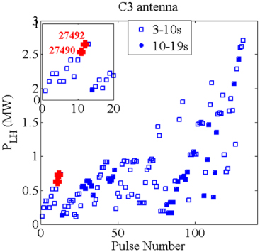
Figure 1. Time history of launched power in the early stage of conditioning of a Tore Supra antenna.
Download figure:
Standard image High-resolution image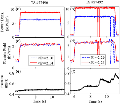
Figure 2. (a), (b) RF power density, (c), (d) electric field, (e) (f) neutral pressure for two consecutive pulses. The first breakdown occurs for pulse 27492. Electric field amplitudes have been low-pass filtered. Time-averaged electric field (in kV cm−1) in the two modules (module 3, solid line and module 4, dotted line) is indicated for the two pulses.
Download figure:
Standard image High-resolution imageThe expected beneficial effect of increasing the wave frequency on the multipactor threshold was also verified experimentally on a wide range of frequencies (1–8 GHz) [7].
Since the discovery of this resonant non-linear growth rate of electron population in RF cavities or waveguides [8], modelling of the multipactor has been carried out by several authors [9–13]. This resonance occurs, in the case of a simple oscillating electric field (no magnetic field), when the transit time τ of an electron from a waveguide wall to the opposite wall equals an odd number of RF half-periods τ = (2N − 1)/(2f) where N = 1, 2, 3 ... is the order of the multipactor and f the frequency of the wave.
These models are generally relevant for quite simple RF components and in particular waveguides are modelled as infinite parallel planes, ignoring finite height (along the tokamak's poloidal direction) and specific boundary conditions (open waveguide to launch the power to the plasma). Moreover in a tokamak, a complex static magnetic field is superimposed on the RF EM field. The effect of this magnetic field is scarcely considered, or computation has only been made with a magnetic field in just one direction, perpendicular to both the RF electric field and the direction of propagation [13]. Numerical codes are now available to take into consideration the full geometry of the waveguides of LHCD antennas [14] and the slowly varying in space 3D static magnetic field.
2. Electromagnetic field in LHCD antenna waveguides
For multi-megawatt LHCD antennas, as installed on JET, JT-60U, Tore-Supra, EAST, the under-vacuum antenna is composed of several modules. Each module has one input waveguide connected to the pressurized waveguide of the transmission line via a window. In the antenna, the power is first divided in the poloidal directions in order to feed a different row of waveguides. The power is further divided in the toroidal direction to end up with narrow waveguides at the extremity facing the plasma. This toroidal power divider is called 'multijunction' and is obtained by inserting walls in the feeding waveguide. The height of some waveguides is reduced in order to change the wave velocity and therefore to adjust the phase at the output. This RF design has an important consequence for the amplitude of the electric field in the waveguide. A tokamak plasma is not a perfectly matched load for the antenna and electric field reflection coefficient (RC) in the range of 20–50% are commonly obtained. The reflected wave propagating backwards will be reflected forwards at the multijunction discontinuity as long as the phases of the merging waves are different. As an example, for JET and Tore Supra antennas, the wave undertakes two round trips before leaving the multijunction. As a first approximation, the electric field amplitude is given by E = E0(1 + RC)2, where E0 is the forward electric field, which has to be compared with the electric field in antennas without a multijunction (usually the case for smaller antennas): E = E0(1 + RC). The phase shifters, obtained by reducing the height of the waveguide, further increase the electric field. The pattern of the electric field in a multijunction, as computed by a full wave software, is shown in figure 3 for two realistic cases of reflection by the plasma. The amplitude of the standing wave increases from 4.1 kV cm−1 to 5.0 kV cm−1 when R increases (2.95 kV cm−1 with RC = 0). The enhanced electric field (by ∼1 + RC) in the for-waveguide section (L > 700 mm) is clearly modelled.

Figure 3. Amplitude of the electric field in a multijunction of a LHCD antenna (f = 5 GHz) along the propagation direction, for two cases of reflection from the plasma. The antenna opening, where the power is coupled to the plasma, is on the right (L = 1170 mm). Reflection coefficient is varied by varying the plasma density from 2 × 10¹⁷ m−3 (solid line) to 10 × 1017 m−3 (dashed line). Waveguide widths b of the three sections of the antenna are indicated above the figure (a = 58 mm).
Download figure:
Standard image High-resolution imageThe static magnetic field, which ensures the confinement of the plasma, is composed of the toroidal field (resulting from the magnetic coils) and the much weaker poloidal field (resulting from the current circulating in the plasma torus). In the narrow waveguides of the antenna which are well inside the iron magnetic circuit, these fields decrease as 1/R for the toroidal field and 1/r for the poloidal field where R and r are, respectively, the distance to the tokamak magnetic axis and the plasma centre.
In this paper, we will focus the analysis of the power limit in the narrow waveguides near the plasma and, at the other end of the antenna, the main wide waveguide connected to the RF window. This latter part of the antenna usually has to cope with very high power density and, taking into account the low reflection coefficient with the multijunction, the electric field can be as high as the one in the narrow waveguides. For such a remote area, the magnetic field may have components (poloidal, toroidal and radial) of the same order of magnitude. As discussed in section 5, the RF power threshold can be strongly reduced when the total field is close to the field Bres for which the electron cyclotron frequency qeBres/2π me equals the frequency of the wave. Computation has been made for Tore Supra (Ip = 0.8 MA, Bt,0 = 3.8 T) and for ITER (Ip = 15 MA, Bt,0 = 5.3 T). In the case of Tore Supra, the magnetic field in the vicinity of the RF window (R ∼ 6.1 m) is very small with respect of the resonance field and the resonance condition occurs just behind the multijunction (R ∼ 4.3 m) in the feeding wide (b = 19 mm or 34 mm) waveguide (figure 4(a)). In the ITER case, the magnetic field exceeds 1 T at the window location (R ∼ 11.5 m) and no resonance occurs in the entire antenna (figure 4(b)).

Figure 4. Dc magnetic field profile near the electron cyclotron resonance layer (thin dashed line). (a) Tore Supra (Bt,R=2.4 m = 3.8 T, Ip = 0.8 MA). (b) ITER (Bt,R=6.2 m = 5.3 T, Ip = 15 MA). The width b of the antenna waveguides at the corresponding radius is indicated.
Download figure:
Standard image High-resolution image3. Multipactor modelling
Modelling was performed mainly with the commercial software FEST3D whose full description can be found on the website of Aurora Software and Testing5. An in-house code MULH was also developed [15] and results were cross-checked in the case of simple geometries. An important input of the code is the SEY which is known to depend on the material, the surface roughness, the surface contamination. These parameters can be changed, and the SEY decreased, by thermal baking or by what is called 'RF conditioning'. This technique combines short pulses on vacuum (with very high reflection, R ∼ 1) and longer pulses on plasma discharges (with lower reflection) with increasing RF power from pulse to pulse. Secondary electron emission is a complex physical process which includes 'true' secondary emission, inelastic backscattering and elastic reflection. The analytic calculation of SEY is a very difficult task and we use here, as in most simulations, Vaughan's empirical fit giving SEY as a function of the energy of the incident electron (Ei) [16]. This model shows that, for perpendicular impact, SEY normalized to the maximum value SEYmax depends only on Ei, the energy for which SEY is maximum (Emax) and a fitting parameter Efit. For an oblique incidence of the primary electron, two more parameters are needed: the incidence angle and a parameter accounting for the surface roughness. It should be noted that for low energy of the primary electron, SEY → 1 and most electrons are reflected (elastically primarily).
Most simulations have been performed for copper with SEYmax = 2.3 and Emax = 165 eV. These values are those of unbaked copper and are therefore pessimistic as all antennas are baked in situ at least up to 100 °C (200 °C on Tore Supra, 240 °C on ITER). Efit is usually set to 12.5 eV but was adjusted in these codes to fit the experimental cut-off E1, the energy for which SEY = 1. For unbaked copper, E1 = 35 eV and Efit was increased to 22 eV (figure 5). Below E1, SEY is assumed to be constant (0.5) to realistically account for elastic and inelastic reflection at low energies.

Figure 5. SEY as a function of the primary electron energy (normal incidence) implemented in FEST3D and MULH for unbaked copper (Efit = 22 eV, E1 = 35 eV, Emax = 165 eV, Ymax = 2.3). The dashed line is Vaughan's empirical fit at low energy.
Download figure:
Standard image High-resolution imageFEST3D and MULH are particle-in-cell (PIC) codes. Electrons are launched with random angles and energies ranging from 0 to 10 eV. However, it has been shown that the details of the population of seed electrons have little effect on the breakdown. Secondary electrons are assumed to have a Maxwell–Boltzmann distribution of energy and an angular distribution following a cosine law (with maximum probability for normal to surface emission).
Starting from the initial position and velocity of seeding electrons, electric and magnetic fields are computed from Ampère's and Faraday's laws on the 3D space grid at each time step, following the algorithm of figure 6 [15].
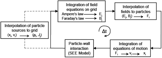
Figure 6. Particle-in-cell scheme for evolving field and particle quantities in one time step.
Download figure:
Standard image High-resolution imageThe RF electromagnetic field map, such as that shown on figure 3, can be imported from a plasma–antenna coupling code, but in this paper we just consider the forward wave E0 cos(ωt − kz) and the reflected wave by the plasma is not included.
The PIC technique is known to be potentially noisy and, in addition, the SEE model leads to intrinsic stochasticity. The accuracy in the determination of the multipactor threshold is determined from 208 runs of the MULH code (figure 7). The standard deviation σ normalized to the mean value μ is less than 2% and about 2% of the runs have a deviation to μ exceeding 3 σ.

Figure 7. Histogram of electric field threshold. The total number of MULH code runs is 208 (a = 72.14 mm, b = 8 mm, length = 100 mm, 3.7 GHz, 100 seed particles).
Download figure:
Standard image High-resolution imageThe thresholds obtained from FEST3D and MULH were compared for rectangular waveguides used for various multijunctions (table 1). The averaged electric field threshold does not vary by more than ∼3% between the two codes.
Table 1. Electric field threshold for various waveguides. Values are averaged on 100 runs. Typical standard deviation is 0.04 kV cm−1.
| Tore Supra C3 | Tore Supra C4 | JET | ITER | |
|---|---|---|---|---|
| b/a (mm) | 8/70 | 14.65/76 | 9/72 | 8.25/56 |
| f (GHz) | 3.7 | 3.7 | 3.7 | 5.0 |
| Eth-FEST3D (kV cm−1) | 2.96 | 3.25 | 3.13 | 4.07 |
| Eth-MULH (kV cm−1) | 3.01 | 3.24 | 3.02 | 4.20 |
The sensitivity of the multipactor threshold to the number of seed electrons N was also verified. For each case, the FEST3D code was run ten times. When N is increased from 100 to 700 electrons, the power threshold, averaged on 10 runs, is decreased by 7% (3.5% for the electric field) and the standard deviation from 6% to 2% (figure 8(a)).
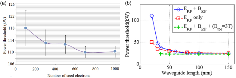
Figure 8. Power threshold as a function of (a) the number of seed electrons (a = 72.14 mm, b = 22 mm, 3.7 GHz), (b) length of the waveguide (a = 72.14 mm, b = 8 mm, 3.7 GHz) from the FEST3D code.
Download figure:
Standard image High-resolution imageEach section of the antenna with constant dimensions (width and height) has a length exceeding 100 mm. In order to reduce the computing time the shortest possible waveguide is desired; this length was determined by studying the convergence of the multipactor threshold with waveguide length using open ends (at input and plasma) where electrons are lost. When the full electromagnetic wave is applied, the threshold increases sharply for short waveguides (figure 8(b)). This is the result of the radial drift of the electron motion caused by the RF magnetic field (∼10−3 T) and many particles leave the waveguide before multipactoring. When this magnetic field is removed, this drift is suppressed but the threshold is still larger for very short waveguides accounting for secondary electrons with oblique emission. For the case of the narrow waveguides of the multijunction, the strong toroidal field (∼3 T on Tore Supra, ∼4 T on ITER) 'freezes' the electron trajectory (primary and secondary) along the field lines and the threshold is constant for all lengths (35–150 mm). This demonstrates that simulating an open waveguide does not lead to a higher threshold.
When the threshold is exceeded by a factor 1.1–1.2, the electron population increases steadily with an amplification factor which can be of the order of 10 every 100 ns, as verified on 3 orders of magnitude. Close above the threshold, there is a phase, which can last 100 ns, where the number of electrons does not vary much. A fine scan of the power near the threshold shows clearly the transition from the electron population decay to the electron amplification and shows that this transition is indeed very sharp (37.5 kW in the case shown in figure 9).
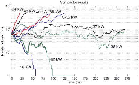
Figure 9. Electron number evolution for various RF powers (f = 3.7 GHz, b = 9 mm, a = 72 mm). Simulation is stopped when the electron number reaches 500. The threshold is determined to be 37.5 kW.
Download figure:
Standard image High-resolution image4. Electric field threshold for the waveguides used in LHCD antennas
The electric field threshold is investigated for a large set of LH antennas in different tokamaks with operating frequency varying between 0.8 and 8 GHz, while the width b of the waveguides varies between 5 and 35 mm. It should be emphasized that the electric field threshold can be easily translated in terms of power threshold for a single waveguide, but for a complex antenna such as those using multijunctions, this is a more complicated task as the field varies from one waveguide to the other. In that case the total power which can be transmitted is lower than that extrapolated from the waveguide with the highest field. The waveguide's material is copper, stainless steel (SS) or titanium. For each case, the threshold is modelled with FEST3D or MULH (figure 10). Discrepancy between the results given by the two codes is very small, less than 5% in most of the cases. For a given material, the threshold scales linearly with the frequency with small deviation. Copper has a higher SEYmax(2.3) than SS (2.0) or titanium (1.9) and the threshold is lower by ∼13% (∼27% in power).

Figure 10. Threshold for various LHH and LHCD antennas from simulations performed with (a) FEST3D, (b) MULH.
Download figure:
Standard image High-resolution imageThis linear scaling is drastically different from the f2 · b scaling found by early authors. This scaling originates from computation considering single multipactor order only but, when combining regions of different orders, a linear scaling of the electric field with the frequency is found. This line can shift in position depending on the assumption made on secondary electron velocity. Two cases were considered: the secondary electrons have a velocity proportional to the velocity of the incident electron ('constant-k' theory) or a constant velocity ('constant-v' theory). These theories do not take into account the non-deterministic nature of secondary emission when the energy of the primary electrons exceeds a few tens of eV and a non-stationary statistical theory gives a more accurate prediction of the threshold [17]. In that case, the energy of these secondary electrons is found to be rather independent of the primary electron energy and to have a rather broad distribution peaked at ∼2 eV [18]. In the codes used for this work, it is assumed that secondary electrons follow this distribution, with a spread of 3 eV. Below 3 eV, results can be very sensitive to this value, but such a sensitivity is lost above this energy.
When comparing with experimental data of LHCD experiments carried out with a parallel refractive index N∥ varying in the narrow range 1.7–2.3, the two scalings should finally not differ much when one remarks that re-rewriting equation (1) as

we conclude that f · b is quasi-constant for present-day experiments with π/2 phasing, which is the most common one (∼37 GHz mm for N∥ = 2).
These plots show a second order effect of the width b. This is, for example, the case for the SS/2.45 GHz points. The threshold increases significantly when b increases from 10 mm (VersatorII) to 15 mm (FT).
This parameter was scanned in a wider range for two frequencies. It is found that Eth/f is actually independent of b in the low-b limit (figure 11). This result is consistent with experimental results performed at 9.5 GHz with b(f × b) varying between 0.2 mm (2 GHz mm) and 4 mm (40 GHz mm) [19], confirmed by modelling [20]. When b is increased, the threshold increases with a constant slope as long as f × b is lower than ∼100 GHz mm. The slope increases with f and the threshold normalized to frequency becomes significantly larger (∼+15%) at 5 GHz when compared with 3.7 GHz. For values of f × b exceeding 100 GHz mm, the threshold increases sharply and disappears for f × b ∼ 125 GHz mm. This is the consequence of the drift of the particles along the poloidal direction from the high RF electric field zone (y = 0) to the low-field zone (y = ±a/2) with the RF magnetic field. This effect increases when the transit time from one face to the opposite face of the waveguide increases and therefore depends on the ratio b/a. An analytical formula can be derived for the condition of non-multipactoring [21]

As a ∼ λ0 = c/f, this condition can be written as

where k = a/λ0 = 0.89 (3.7 GHz case)−0.97 (5.0 GHz case), with δmax = 2.3, this condition is now

in full agreement with the PIC modelling.

Figure 11. Electric field threshold normalized to the frequency as a function of the width b of the waveguide (SEYmax = 2.3, Emax = 165 eV). Dashed vertical lines indicate the b threshold for multipactor suppression (from equation (3)) for a = 58 mm and a = 72 mm. Cases of N∥ = 2 PAM antennas are indicated with diamond symbols for the two frequencies.
Download figure:
Standard image High-resolution imageThe benefit of increasing the frequency from 3.7 GHz (Tore Supra, JET) to 5.0 GHz (ITER) can now be estimated precisely. This is carried out for a passive–active multijunction [22] whose design is optimized for ΔΦ = 3π/4. For N∥ = 2.0, the width b has to be decreased from 13 to 9 mm and the threshold normalized to the frequency is the same for both antennas.
5. Multipactor modelling with static magnetic field
The dc magnetic field of the tokamak environment confines the electrons and strongly reduces the radial and poloidal drift. We first examine the case of a simple toroidal field with no poloidal field. This is the situation on a superconducting tokamak, such as Tore Supra or ITER, when the antenna is conditioned before plasma operation or between plasma pulses. A field of ∼5 × 10⁻³ T is sufficient to suppress the drift caused by the RF magnetic field (∼1 × 10⁻³ T) and the threshold is reduced by ∼22% (∼6%) for the b = 22 mm (8.25 mm) waveguide. A strong resonance is observed when the field is such that the electron cyclotron frequency (qeB/2πme) equals the wave frequency (0.132 T at 3.7 GHz) and the threshold decreases from 2.5 to ∼1 kV cm−1 for the b = 22 mm waveguide. The order of the multipactor is also much larger at the resonance. The resonance effect is weaker for the narrow waveguide with a reduction in the threshold by ∼20% only. For any other values of the magnetic field up to the value reached at the opening of the antenna (∼3 T on Tore Supra), the threshold is unchanged (figure 12).
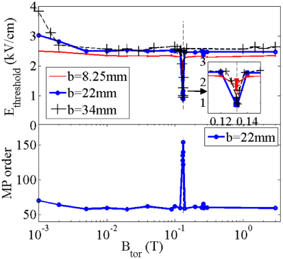
Figure 12. Effect of toroidal field on threshold (top) and multipactor order (bottom).
Download figure:
Standard image High-resolution imageWhen the poloidal field is added to the toroidal field (case of a plasma discharge), the total resulting field may increase or decrease the threshold. For the multijunction with narrow waveguides, where the field is the highest with typical values Bpol ∼ 0.1–0.3 T, Btor ∼ 2–3 T, the addition of the poloidal field has no effect on the threshold. For low-field values (Bpol, Btor ∼ 0.1–0.4 T) as is the case on Tore Supra and on JET behind the multijunction (see figure 4(a)), the threshold is enhanced specifically when Btor ∼ Bpol (figure 13(a)).
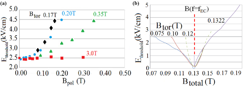
Figure 13. Electric field threshold as a function of (a) the poloidal field for four toroidal field values, (b) the total field near the resonance (f = 3.7 GHz).
Download figure:
Standard image High-resolution imageThe electron cyclotron resonance was found to be related to the value of the EC frequency for the total field
 (figure 13(b)). With increasing toroidal component, the resonance gets sharper. Although the radial field is not included in these simulations, we checked that the radial field and poloidal field alone have a very similar effect on the particle dynamics and the threshold. This effect would be identical in the infinite plane approximation (infinite height a and infinite length).
So far all the simulations have been performed with SEY values of unbaked ('as received') copper. Effect of baking was estimated for the ITER input waveguide (29 mm×58 mm). Although the static magnetic field gradient in the radial direction is high (1–2 T m−1, see figure 4(b)), the computation was performed with a uniform field along this direction. For baking temperatures varying between 100 and 350 °C, SEYmax of copper decreases from 1.9 to 1.4 [23]. It results in increasing the multipactor threshold at 5 GHz from 4.3 kV cm−1 (unbaked) to 9.9 kV cm−1 (figure 14). For the baking temperature envisaged on ITER (240 °C), the threshold (7 kV cm−1) is below what would be required to transmit 500 kW assuming a power reflection coefficient of 5% (8.8 kV cm−1). However, when the gradient is included in the simulation (with a quite large radial mesh of 5 cm), the multipactor disappears.

Figure 14. Electric field threshold as a function of the baking temperature. The assumed SEYmax (1.4–2.3) is indicted for each point.
Download figure:
Standard image High-resolution image
6. Discussion and conclusions
Tri-dimensional multipactor modelling of LHCD antennas in a tokamak environment allows one to precisely predict the frequency scaling of the electric field threshold. The extrapolation from present-day antennas operated at 3.7 GHz (JET, Tore-Supra) to the foreseen ITER antenna at 5 GHz [24] indicates that, comparing antennas launching the same RF spectrum (N∥ = 2), the electric field limit in the narrow waveguides of the multijunction would be exactly increased by the ratio of operating frequency 5/3.7 = 1.35, assuming identical narrow septa (2.2 mm). For 4 mm wide septa, the scaling factor is 1.3. The computation was performed with a very pessimistic value of SEY, corresponding to unbaked copper, but this scaling factor is expected not to vary by much with SEY. Including the static magnetic in the modelling reduces the threshold by less than 10% for narrow waveguides (b < 15 mm). The scaling factor should not also be affected by this parameter.
The translation of this electric field limit in terms of launched power density would require detailed investigation of the EM properties of the antenna and mapping the electric field, especially in the multijunction (as shown in figure 2) for realistic coupling conditions between the antenna and the plasma. Work is in progress to optimize the design of the ITER multijunction aiming at minimizing the electric field while keeping the wave directivity for current drive as high as possible and power reflection towards the RF source low enough during transient and periodic mismatch of the antenna to the plasma, namely during the ELMs.
It should be emphasized that the details of the strength of the toroidal and poloidal fields as long as Btor is much larger than Bpol which is always the case in the multijunction have no effect on the multipactor threshold (figures 11 and 12(a)) and no uncertainties arise when comparing different magnetic equilibria (on the same tokamak or between different tokamaks). Conversely, at the vicinity of the antenna input where wider waveguides are used, a drastic decrease in the threshold occurs in a narrow antenna section where the wave antenna is close to the electron cyclotron frequency (B ∼ 0.2 T). From the experimental point of view, this has not been identified as a limit on Tore Supra at least when the antenna is conditioned. On ITER, this resonance condition does not occur but multipactoring in the WR229 waveguide (29 mm × 58 mm) is predicted when a homogeneous magnetic field is taken into account with a threshold (7 kV cm−1 after 240 °C baking) which could be limiting for a 20 MW antenna.
Static magnetic field gradient and also modulation of the RF electric field resulting from the standing wave ratio (large in the multijunction, small in the input waveguide) are not included in this modelling. Both are expected to increase favourably the multipactor threshold. The effect of a radial gradient of the magnetic field was checked in a preliminary test and the threshold of 6.4 kV cm−1 mentioned here above disappears showing that indeed this quantity is important.
A complete description of the electric field handling capability of an LHCD antenna should include the window featuring a ceramic disc in a complex geometry and will be addressed in a future work.
Finally, an extrapolation of JET results showing that an average power density of ∼15 MW m−2 (25 MW m−2 on 1/6 of the antenna) could be coupled to H-mode plasmas [6] would indicate that 25 MW m−2 (43 MW m−2 if the result on 1/6 of the JET antenna is extended to the whole antenna) can be achieved at 5.0 GHz on ITER, assuming the same plasma–antenna coupling on both devices. Optimization of the antenna design should slightly increase these numbers.
Acknowledgments
This work, supported by the European Communities under the contract of Association between EURATOM and CEA, was carried out within the framework of the European Fusion Development Agreement. The views and opinions expressed herein do not necessarily reflect those of the European Commission.
Footnotes
- 5
Aurora Software and Testing, S. L. FEST3D website, 2012. URL www.fest3d.com/. 53, 54.