

Abstract
In this paper, we propose an experiment for analysing harmonic motion using an iPhone's (or iPad's) magnetometer. This experiment consists of the detection of magnetic field variations obtained from an iPhone's magnetometer sensor. A graph of harmonic motion is directly displayed on the iPhone's screen using the Sensor Kinetics application. Data from this application was analysed with Eureqa software to establish the equation of the harmonic motion. Analyses show that the use of an iPhone's magnetometer to analyse harmonic motion is a practical and effective method for small oscillations and frequencies less than 15–20 Hz.
Export citation and abstract BibTeX RIS
1. Introduction
The motion is defined according to the displacement of an object that can move on a straight or circular line with vibrations or random routes. Kinematics aims to describe the motion of an object and predict variations in motion according to time. A variety of experiences and materials for use in physics lessons have been developed in accordance with this aim. Using a simple chronometer can even give us some information about the motion of an object. However, observing an object's position variation requires more complicated tools than a chronometer, as in the case of periodic motion that is defined as 'the motion of an object that regularly returns to a given position after a fixed time interval' [1].
Our literature review in Institute of Physics Publishing journals shows that there are numerous studies on analysing harmonic motions. Among these studies, we found the use of an optical mouse [2], Nintendo Wii controllers [3, 4], coils [5], and iPhone accelerometer sensors [6, 7] to collect and analyse data on harmonic motion. In this paper we aim to show how an iPhone's magnetometer can be used for the analysis of harmonic oscillations. This method consists of analysing the change in the magnetic field near an iPhone's magnetometer.
A simple experiment shows that a magnetometer sensor measures the magnetic field where an iPhone is placed. As soon as we approach a magnet, the magnetic field nearby will change. However when the magnet isn't moved, the value of the magnetic field will stay as the same. When we move away the magnet below and above (or left and right) of an iPhone, we could observe peaks of magnetic field on the iPhone's screen using an iOS application such as Sensor Kinetics Pro [8]. Accordingly, amplitudes of the peaks will depend on the elongation of magnet: the greater the elongation is, the greater the amplitude will be. If this motion is repeated periodically, the peaks will be periodic. In this context, we propose to analyse two harmonic motions involving a simple harmonic oscillator and a simple pendulum.
2. Experiment 1: simple harmonic oscillator
The term 'simple harmonic oscillator' defines the motion of an object 'whenever its acceleration is proportional to its position and is oppositely directed to the displacement from equilibrium' [1]. The differential equation for a simple harmonic oscillator (horizontally oscillated spring of mass m and spring constant k at the x-axis) is given by [9]

The solution of this equation is

where  is the angular frequency and
  is the phase. The period of harmonic motion is

where m is a suspended mass to the spring and k is the spring constant. This equation is also the same for a spring that is vertically oscillated [10]. We assert that equation (3) is a stimulation period of an iPhone's magnetometer sensor near a suspended magnet on a mass that is oscillating near an iPhone.
2.1. Experimental setup
A spring whose spring constant is known was vertically suspended, as shown in figure 1. A mass of 500 g was at the other extremity of the spring. A small neodymium magnet in a cylinder form ( mm and
  mm) was attached in the middle of the mass. This magnet was preferred because of its mass (
 g). A ruler was placed across the system mass and spring. An iPhone with the Sensor Kinetics application was put on the ruler such that iPhone is at the equilibrium point of the system. The spring was pushed so that it moved vertically with a small oscillation (
 1 cm).

Figure 1. The simple harmonic oscillator experiment with an iPhone. The oscillation is at the z-axis.
Download figure:
Standard image High-resolution imageWe used the default settings for the magnetometer sensor in the Sensor Kinetics application. When this application was turned on, harmonic motion became visible on the iPhone's screen. The change of magnetic field nearby at three axes was detected by the magnetometer (figure 2). However, the function at the z-axis was more regular than others for our experimental setup. A sine curve at this axis was visible on the screen. The period of the oscillation is the difference of time between the two successive peaks and it can be measured on the iPhone's screen with the zoom function. This curve between the magnetic field and time represents the function of a simple harmonic oscillator. We examined in the first 40 s of motion for neglecting under-dumped oscillations.

Figure 2. Function of harmonic motion for a spring (k = 40 N m−1) on an iPhone's screen (top) and measuring period of the oscillation (bottom).
Download figure:
Standard image High-resolution image2.2. Mathematical function for experimental data
Data from an iPhone's magnetometer sensor was exported in csv format with the Sensor Kinetic application. Then, data was analysed with Eureqa software [11, 12] and the magnetic field function at the z-axis was found as the following relationship:

where A refers to the amplitude of magnetic field the at z-axis,  a constant and
  the angular frequency. This constant B0 refers to values of magnetic field at the equilibrium position. This value could not be zero because a neodymium magnet keeps stimulating the magnetometer at this point.
The magnetic field's function in microteslas at the z-axis for the spring k = 40.07 N m−1 with 500 g mass (+0.3 g mass of the magnet) versus time in seconds is as follow:

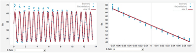
According to equation (5), the angular frequency of harmonic motion is 8.65 rad s−1 and the period of the motion is 0.73 s according to equation (3). This harmonic oscillation was obtained by moving the spring 1 cm away from the equilibrium position. The solution fit graph given by Eureqa software for this equation is shown in figure 3. The goodness of fit for this solution is R2 = 0.995.

Figure 3. Magnetic field at z-axis in microteslas versus time in seconds (left) for oscillated spring (k = 40.07 N m−1) and magnetic field in microteslas at z-axis versus position in centimetres (right).
Download figure:
Standard image High-resolution imageWhen the angular frequency and elongation of spring are known, the relationship between position and magnetic field at the z-axis can be analysed. According to equations (2) and (5), the solution of harmonic oscillation can be written below for 1 cm elongation at the z-axis in centimetres versus time in seconds

Data from two functions (equations (5) and (6)) were analysed with Eureqa. The solution fit graph is shown in the right of figure 3 and the function of change of the magnetic field in microteslas at the z-axis versus position in centimetres is

This equation is valid for maximum and minimum elongation of spring ( ). According to this equation, when the spring is 1 cm below the equilibrium position (
 cm) magnetic field is found as −38.21 μT. When the spring is 1 cm above the equilibrium position (
 cm) the value of the magnetic field is found to be −24.99 μT. At the equilibrium position (z = 0) the magnetic field was −31.6 μT. So, the magnetic field around the iPhone is between −24.99 μT and −38.21 μT (figure 3).
2.3. Verification of experimental results
We used three different springs to verify experimental and theoretical results. All experiments were carried out with small oscillations (approximately a 1 cm elongation of the spring). We first calculated the period with data from Eureqa such as in equation (5). Second, we calculated the same period using the theoretical relationship given in equation (3). Then we compared two values of the period. Results given in table 1 show that experimental and theoretical results are very close or equal to each other.
Table 1. Period of harmonic oscillation for the three springs.
| Trial | k (N m−1) | TEureqa(s) |
Ttheo(s) |
|---|---|---|---|
| 1 | 29.85 | 0.81 | 0.82 |
| 2 | 40.07 | 0.73 | 0.70 |
| 3 | 48.85 | 0.64 | 0.64 |
a refers to experimental values of period according to the magnetic field function in Eureqa. This is also the stimulation period of the iPhone's magnetometer sensor by the harmonic oscillator.
b
refers to experimental values of period according to the magnetic field function in Eureqa. This is also the stimulation period of the iPhone's magnetometer sensor by the harmonic oscillator.
b refers to theoretical values of period.
3. Experiment 2: simple pendulum
In our experimental setup a simple pendulum was created with a metal bob and suspended to one end of a string of length  (figure 4). The other end was placed on a metal bar through a metal ring to reduce friction. Oscillation was produced with small angles (
 ). In this case the motion can be considered as a simple harmonic oscillator. Its differential equation is given by [1]

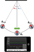
Figure 4. Simple pendulum experiment with an iPad. The oscillation is at the x-axis.
Download figure:
Standard image High-resolution imageThe solution of this equation is

where  is maximum angular position,
  angular frequency and
  is the phase. The period of harmonic motion is
where  is length of the string and
  is gravitational acceleration.
We were interested in the first 10 s of harmonic motion for neglecting under-dumped oscillations. Depending on the direction of elongation, the function of the harmonic motion was obtained from the iPhone's screen using the Sensor Kinetics application. The iPad was placed under the metal bob at the equilibrium position. At the equilibrium position, similarly to the spring system in the simple harmonic oscillator, the value of the magnetic field was called B0 and the magnetic field was observed between Bmax and Bmin. For example, when a simple pendulum ( cm) was oscillated with an angle
  (0.07 rad), the change of the magnetic field in microteslas at the x-axis versus time in seconds is given by Eureqa with the equation (R2 = 0.98)

According to equation (11), angular frequency of harmonic motion is 7.77 rad s−1 and the period of the motion is 0.80s according to equation (10). The solution graph for this equation is given in figure 5. When the relationship between angle of oscillation in radians and Bx in microteslas, we obtained the following equation

for  with R2 = 0.98. According to the equation (12), it is shown that magnetic field is oscillated between 48.21 μT and 65.99 μT (figure 5).
Figure 5. Magnetic field at the x-axis in microteslas versus time in seconds (left) for a simple pendulum of 16 cm and magnetic field at the x-axis in microteslas versus angle in radians (right).
Download figure:
Standard image High-resolution image
We conducted experiments with four strings of different length. We first calculated the value of the period using data from Eureqa such as in equation (11). Second, we calculated the period using theoretical relationship given in equation (10). Then we compared two values of the period. Results in table 2 show that experimental and theoretical values of the period are very close or equal to each other.
Table 2. Period of simple pendulum for various strings length.
| Trial | l(m) | TEureqa(s) |
Ttheo(s) [10] [10] |
|---|---|---|---|
| 1 | 0.16 | 0.80 | 0.80 |
| 2 | 0.32 | 1.12 | 1.13 |
| 3 | 0.42 | 1.30 | 1.30 |
| 4 | 0.51 | 1.44 | 1.43 |
a refers to experimental values of period according to magnetic field function in Eureqa. This is also stimulation period of an iPhone's magnetometer sensor by a simple pendulum.
b
refers to experimental values of period according to magnetic field function in Eureqa. This is also stimulation period of an iPhone's magnetometer sensor by a simple pendulum.
b refers to theoretical values of the period.
4. Results
In this paper, we aimed to show how an iPhone's magnetometer could be used to analyse harmonic oscillations. We found some advantages compared to other methods we emphasized at the beginning of the paper. First, as can be seen in our experiment, it is practical and it does not require any mounting. The same equipment can be used to analyse any type of harmonic motion. For this it is sufficient to have an iPhone (or iPad) with suitable applications and a magnet. Thus, the effect of an observer on the moving system (spring or pendulum) is also minimized with a small neodymium magnet. Second, this method also offers advantages for the visualization and analysis of data from the magnetometer. By this method, we can spontaneously visualize the function that represents the harmonic motion. We can help students to compare the trajectory of the system and its function. Regarding the analysis of data, we can use our method to determine simply the period of the harmonic motion during the class by projecting the iPhone's screen. It is suggested that a more detailed analysis after the lecture could be performed by students to obtain the differential equations of the harmonic motion with Eureqa, which is free for both students and teachers.
Despite the advantages mentioned above, there are also some inconveniences. Analysing harmonic motion with an iPhone's magnetometer requires small oscillations. Otherwise, the neodymium magnet stimulates the magnetometer twice and harmonic motion cannot be correctly visualised and analysed. On the other hand, measures are valid for frequencies less than 15–20 Hz with the application we used on the iPhone. Beyond this frequency, one cannot correctly measure the rate of a magnetic field's change near an iPhone.
Biographies

Ahmet Yavuz is a lecturer of physics at the Nigde University in Turkey. His research is based on the teaching and learning of physics, in particular problem solving. Currently, he conducts studies on the integration of new technologies and the development of physics teaching materials.

Burak Kağan Temiz is a lecturer of physics at the Nigde University in Turkey. His research is based on physics education, problem solving and science process skills. More recently, he has been dealing with the design and development of physics teaching materials.