


Abstract
A wetting liquid brought in contact with a solid covered by microtextures invades the network of textures and fills it, creating a liquid film whose thickness is fixed by the texture height. However, this process of filmification can be opposed by the presence of surrounding menisci, residing for instance in corners at the edges of the film. We discuss the nature to be given to the texture to overcome the negative Laplace pressure associated with menisci. We also describe how the dynamics of filmification is impacted by the design of the texture, focussing on micropillars, lines and grooves, and how it can be optimized for some texture density. We conclude by discussing the distribution of textures generating a constant velocity of filmification instead of the slowing-down classically observed in impregnation processes.
Export citation and abstract BibTeX RIS
Introduction
Covering a flat surface by a liquid film – "filmification" in one word – is an art that a few natural systems have mastered. Some tropical plants use it as strategy to evaporate water as quickly as possible in areas with frequent rain [1], while others, like carnivorous pitcher plants, exploit it to create slippery surfaces to trap insects [2]. Typically, the surfaces of these plants are covered with wettable cones, grooves or pores, rendering them micro-rough and superhydrophilic. Roughness wicks the liquid and selects the film thickness. In addition, it improves and speeds up spreading. Bico et al. have shown that spontaneous spreading of a liquid on a model rough surface occurs if [3]:
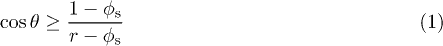
where θ is the static contact angle of the liquid on a flat surface, r is the roughness factor, defined as the ratio of the total to the projected surface area, and  the texture density on the surface. Derived from the roughness factor r, we introduce the excess roughness
  , seen further to govern the whole process of filmification. Using this excess parameter, we can re-express the condition for filmification of a given liquid, having a contact angle
  on a flat surface:

Completely wetting liquids  make films whatever the texture, since
  and eq. (2) is always satisfied. As the contact angle θ approaches
  , the critical roughness
  diverges, and spreading such liquids into a stable film by means of roughness becomes increasingly difficult.
Studies into liquid spreading using rough surfaces are important not only for understanding the survival strategies of plants, but also in daily life, when blotting up spilled liquids from carpet or polishing wooden surfaces, and for improving industrial devices, such as high-performance heat exchangers and oil skimmers. Surfaces microtextured with pillars of well-defined excess roughness Γ (fig. 1(a)) have been extensively studied as model systems [4–11]. An important advantage of such microstructures is the fact that the thickness of the liquid films is directly controlled by their height.

Fig. 1: (Color online) (a) Schematic illustration of the pillar- and line-shaped microstructures used in this paper, defined by their width 2b, height h and pitch p. (b) Artist impression of a curved liquid reservoir in a crevice of size w between plates.
Download figure:
Standard imageIshino et al. showed that the progression of liquids in such 2D porous media obeys a classical Lucas-Washburn law with two main sources of friction: the bottom surface and the pillar walls [6]. Xiao et al. analysed the shape of the liquid front in dense arrays of pillars and used an empirical fit to calculate the capillary pressure driving the spreading [8,9]. Finally, Courbin et al. studied the dynamics of partially wetting liquids on micropillars and found that directionality of spreading can give rise to particular film footprints, ranging from circles to squares [5,7].
Some crucial aspects of filmification, however, have not been taken into account so far. Filmification, spreading and wicking have always been studied with liquid baths or spreading droplets as liquid reservoirs. In reality, liquids often reside in crevices and corners, shaped as menisci with negative curvatures, as for instance in oil sands, spills on carpet and heat exchanger channels. It is harder to cover a surface with a liquid film from a curved meniscus than from a large liquid bath: the negative curvature implies a negative Laplace pressure difference that must be compensated for upon spreading.
Here, we study filmification by microtextures from menisci by constructing liquid reservoirs between two plates with various radii of curvature (fig. 1(b)). We show that a minimum roughness is required to initiate filmification and we elaborate on the nature of this critical roughness for pillars and lines. For both cases, we discuss how and why increasing roughness speeds up filmification initially, but slows it down for very rough surfaces. This analysis provides new insights into the optimum conditions for fast filmification.
Critical condition for filmification
To study the dynamics of filmification from menisci, we made surfaces with the microtextures shown schematically in fig. 1(a). We fabricated cylindrical pillars and straight lines out of SU-8 resist on silicon wafers using photolithography. We first focus on pillars here; the film-forming capabilities of lines and texture gradients are discussed at the end.
We used square arrays of cylindrical pillars (see fig. 1(a)) with a fixed pillar radius b = 17.3±0.8 μm, three different pillar heights ( , 75 ± 5 and 145 ± 3 μm) and a range of different pitch sizes (600 μm > p > 57 μm), covering a vast range of roughnesses
  . The roughness is related to the surface density of pillars
  via simple geometric relations:
 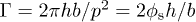 . Alternatively, we can calculate the mean deviation from the mean height
  and the root mean squared roughness
  , with
 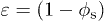 the void fraction.
We brought these surfaces in contact with a reservoir of silicone oil (surface tension 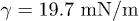 , and viscosity
  , unless specified otherwise) having a negative radius of curvature, set by the thickness w of the spacer between the textured surface and the glass cover slip (see fig. 1(b)). Surfaces were always placed horizontally and we monitored the liquid propagation using a camera placed above or aside.
Silicone oil completely wets both the silicon wafer, glass plate and SU-8, hence,  . According to eq. (2) we expect that it always spreads into a film, whatever the density of pillars. It should be noted that on a surface without any pillars
  , the spreading film only has a nanometric thickness, a situation intrinsically different from liquid films between pillars
  , which adopt the pillar height h, as seen in fig. 2.

Fig. 2: Optical microscope images illustrating liquid propagation between micropillars. The scale bar indicates 100 μm.
Download figure:
Standard imageHowever, we observed that the liquid does not penetrate the micropillar array below a critical surface density of pillars, as shown in fig. 3. If we make the spacer smaller, the curvature increases and it becomes increasingly difficult to induce filmification. Remarkably, the critical pillar density we found does not depend on the pillar height.

Fig. 3: (Color online) Critical density of pillars for filmification of a wetting liquid from a meniscus. Data correspond to a fixed pillar radius b = 17.3±0.8 μm and three pillar heights h. The images show the two distinct states of the textured surface: dry (dark image) below, or impregnated by a film of liquid (bright reflection) above the solid line (eq. (5)).
Download figure:
Standard imageThe existence of a critical roughness to induce wicking must result from the energy associated with the meniscus. The Laplace pressure difference ΔP between the liquid film connected to the meniscus and the surrounding ambient pressure is 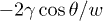 . Extracting a volume
  from this reservoir and extending the liquid film against ΔP corresponds to an amount of work (per unit length of the liquid front L)
  . This must be compensated by the surface energy driving filmification [3]:

where we abbreviated  as γ. Spreading only occurs spontaneously if the energy gain outweighs the cost
  . Hence, there is a critical contact angle of filmification
  given by

The critical angle is modified with respect to eq. (1) due to the presence of a meniscus. If the liquid completely wets the surface  , as is the case for our pillars, a critical excess roughness
  is needed for filmification. For sparsely textured surfaces, such as the pillars used in our experiments,
  and the critical roughness simplifies to
  . In the limit w → ∞, the negative curvature becomes negligible and we find the same criterion as for filmification from a wetting bath:
  . In the limit of strong curvature (small w) found in small crevices, filmification is only possible on very rough surfaces, since
  diverges. In general, filmification is more demanding from menisci than from baths.
Interestingly, the opposite effect of enhanced spreading is expected for filmification and capillary penetration from droplets, as they exhibit a positive curvature and, hence, a positive Laplace pressure difference. In that case eq. (4) becomes  with R the radius of curvature of the deposited drop, and the critical angle
  can exceed
  [12]. For filmification in microtextures this effect is negligible if deposited drops have a radius of curvature much larger than the texture height h.
In the specific case of micropillars, we find a surprisingly simple expression for the critical pillar density  that sets the limit of filmification from menisci. Inserting the excess roughness of micropillars in the expression for
  above results in
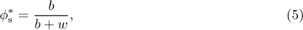
which is independent of the pillar height h, for h < w.
The results in fig. 3 show that eq. (5) provides an accurate prediction for the condition of filmification by micropillars, despite possibly a marginal dependence on the pillar height h. It is worth noting that eq. (5) must follow from an equivalent balance of the local capillary pressure at the spreading front and in the reservoir, like the laws of capillary rise can be found from a balance of hydrostatic and capillary pressures. By rewriting  as
as  , we find an expression for the curvature C of the liquid front between cylindrical pillars:

In general, the liquid front has a complex shape, but eq. (6) shows that the principal radii of curvature that describe it are proportional to the size of the micropillars b and independent of their height h. For sparse arrays of micropillars as used here, the curvature C that drives filmification scales as  . In an attempt to rationalise this simple formula we note that the curvature
 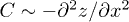 , with z(x) the height profile of the meniscus extending from the foremost wetted pillar. As
  for small pillars, and
  , because the curvature is fixed by the distance at which the front meets the next pillar, the curvature of the interface between pillars is found to scale as
  .
.
Maximum rate of filmification
Beyond the critical pillar density  of eq. (5), the dynamics of filmification follows a characteristic
  -dependence that is known as Lucas-Washburn's law [6,13,14]:

where x is the distance from the liquid reservoir to the front. We extracted the coefficient D in our experiments from the slope of a  plot (see the inset in fig. 4). To understand the dependence of the coefficient D on all geometric parameters, we must solve the force balance that underlies the Lucas-Washburn law in eq. (7). The capillary driving force is given by the change in surface energy (eq. (3)) upon filmification,
  , and it simplifies for a wetting liquid to [3,6]:

per unit length of the liquid front. If the liquid reservoir has a negative curvature, the surface energy must overcome an extra energetic barrier of  , so that the net driving force given by eq. (8) decreases to


Fig. 4: (Color online) The filmification coefficient D is inversely proportional to the liquid viscosity η. These experiments were performed at  and h = 95 μm, using silicone oils of various viscosities. The solid line is a power law fit with slope −1. The inset shows three typical
  graphs at different viscosities.
Download figure:
Standard imageEquations (8) and (9) describe the force that drives filmification on a rough surface in general. The exact nature of the roughness impacts the filmification rate through Γ.
The capillary driving force is balanced by viscous friction. In general, viscous losses occur wherever the moving liquid contacts the solid surface. For pillars, the total viscous friction has been simplified by a sum of two terms: friction due to the bottom surface and friction due to the pillar walls. Although this approach entails a simplification of the actual flow past the array of pillars, it does capture all limits of the viscous dissipation and was found to yield reasonable predictions of filmification coefficients for a variety of pillar arrays [6]. We therefore use the same expression for the total viscous friction here:

where x is the distance from the liquid reservoir to the front, and  is the front velocity. The factor
  is a friction coefficient per unit length of the pillars. Both Hasimoto [15] and Sangani and Acrivos [16] have given numerical expressions for the friction coefficient
  of cylindrical pillars arranged in square and hexagonal arrays. For square arrays:

Balancing the capillary driving force in eq. (9) with the viscous friction in eq. (10) yields a Lucas-Washburn-type expression with a modified coefficient D characterising filmification from menisci in a square array of pillars:

D is expected to be proportional to the surface tension γ, as long as the liquid completely wets the surface, and to be inversely proportional to the viscosity η. We find perfect experimental agreement with the latter prediction, as shown in fig. 4. D is also expected to be proportional to the pillar density  at low
  , provided that h < p. In that case the second term in the denominator of eq. (12), which arises from the friction at the pillar walls, is negligible and D reduces to
  . As p decreases,
  increases and the friction at the pillar walls starts to dominate the friction with the bottom. Since the wall friction increases faster than the driving force with decreasing p, D goes through a maximum and decreases for dense pillar arrays.
Figure 5 compares our experimental filmification rates with eq. (12). The force balance underlying eq. (12) accurately predicts the spreading rates for all possible choices of the geometric parameters h, w and p. We note that the dynamics at large w is quicker than reported previously [6,8], chiefly because the pillars we fabricated are higher, and that filmification slows down for smaller w (stronger curvature). The fits to eq. (12) are quantitative provided we use an effective height h' slightly smaller than h (see inset of fig. 5(a)). The need for an adjusted height h' is likely due to our simplified description of viscous losses: by simply adding the friction of a flat plane and that of infinitely long cylinders, we have neglected the losses in the corners where the pillars are anchored to the bottom surface. Using an effective height smaller than the pillar height is a way to amplify viscous friction (eq. (10)) and leads to a better fit of our data. The relative importance of corners between pillars and bottom is larger for shorter pillars, and we indeed find a bigger difference between the actual and effective height for short pillars.

Fig. 5: (Color online) Filmification coefficients D for surfaces with micropillars of various heights h, as indicated by the labels in (a)–(c). For each height, filmification is initiated from menisci of four different curvatures, set by w and indicated in the legend in (b). D is maximum at a pillar density  , which is plotted as a function of w in (d) for the three pillar heights. The lines in (a)–(c) are theoretical predictions by eq. (12), with a single adjustable height h', plotted in the inset of (a). Dashed lines illustrate the limit w → ∞, corresponding to filmification from a bath. The lines in (d) are solutions of
  .
.
Download figure:
Standard imageEquation (12) predicts a maximum film spreading rate at intermediate pillar densities. The location of the maximum  can be found theoretically from
 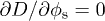 or
or  and is plotted in fig. 5(d). We find good agreement with the experimental values. The optimum pillar density, for which the filmification rate is maximum, decreases with increasing pillar height h. Roughly, this density corresponds to the point where friction at pillar walls starts dominating the friction due to the bottom. Short pillars imply thin films for which friction with the bottom is relatively important, hence friction at pillar walls only dominates in dense arrays of pillars.
Filmification by lines and gradients
Pillars may resemble the papillose cells of certain plants [1], but many more surface textures can be found in nature and industry. In this section, we briefly discuss how changing the type and arrangement of microtextures impacts filmification. We first discuss if the key characteristics of filmification by pillars (critical roughness and maximum rate) are conserved for other textures, such as lines and grooves. We then describe how different texture arrangements may generate new spreading dynamics.
We carried out similar filmification experiments on surfaces with lines (see fig. 1(a)). Lines and grooves between them provide a more efficient way to guide liquid flows [2], to prevent sideways spreading [17], and to induce mixing in channels [18]. The dynamics of filmification by lines again follows Lucas-Washburn's law (eq. (7)), but the characteristics of the coefficient D are different from pillars (fig. 6). We only expect filmification above a critical surface fraction of lines 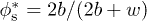 , which is slightly different from pillars. Our experiments show that the filmification rate of lines indeed decreases when decreasing
  , but that it reaches a apparent plateau close to the predicted value of
  , for the two values of w we investigated. Below
  liquid spreading is not completely halted like for pillars, but instead a small amount of liquid still spreads along the two edges bordering each groove (see upper left images in fig. 6).

Fig. 6: (Color online) Filmification coefficients D in grooves as a function of the line fraction for menisci of two different curvatures, set by w. The lines have a height h = 75 μm. Filled symbols indicate grooves filling up and empty symbols grooves remaining empty. The dashed lines indicate the predicted  .
.
Download figure:
Standard imageA closer inspection of the spreading process reveals that filmification between lines consists of two steps: propagation of a meniscus along the lines and filling of the grooves in between two lines. At high line fraction, grooves are narrow and meniscus propagation is quickly followed by the filling stage (see upper right images in fig. 6). However, at low line fraction only meniscus propagation, allowed for by the continuity of the corners between lines and bottom, is observed and the grooves are never filled (see upper left images in fig. 6). A similar distinction between meniscus propagation and filling is expected for continuous microstructures in general. Here, the condition given by eq. (4) only applies to the stage of filling, for which it yields reasonable predictions as evidenced by the dashed lines in fig. 6. Preventing any liquid from spreading is impossible in the presence of continuous edges.
When comparing the rates of film spreading by lines and pillars, lines are found to amount to faster filmification than pillars of comparable height (cf. figs. 5(b) and 6). Surfaces with lines have a larger excess roughness at equal pitch 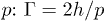 (lines) is larger than
  (pillars) by a factor
  . At high line fractions, filmification rates decrease, like for pillars, as a result of friction at the groove walls.
Finally, it is interesting from a practical point of view to be able to displace liquids at constant flux across the surface, that is, to have a constant velocity for the spreading front instead of a decreasing one [7]. To this end, we fabricated surfaces with a gradient of roughness (using micropillars). The gradient was designed in such a way that  ; hence, as long as
  remains small
  and
and  . While film spreading normally slows down in time (eq. (7)), because of the increased viscous resistance, the coefficient D of this surface increases by the same amount, due to a growing roughness. As a result we observe a linear propagation of the liquid front instead of the all-too-familiar
  -dependence, indicating that film progresses at a constant velocity over a distance of a few centimeters (fig. 7). Propagation eventually slows down, because of friction at the pillar walls, as expected from the decrease in D at high
  in fig. 5.

Fig. 7: (Color online) Dynamics of filmification in a linear gradient of pillar density  , with a constant pillar height h = 75 μm, for
  (blue squares),
  (red circles) and
  (green triangles). The inset shows part of the third gradient, with a scale bar indicating 2 mm.
Download figure:
Standard imageConclusion
We have shown that filmification of liquids from menisci with a negative curvature that occur in crevices and corners like in oil sands and heat pipes, is more difficult than filmification from a bath. We have predicted the minimum roughness required for filmification from a meniscus and discussed how the dynamics of filmification is impacted by roughness and the type and arrangement of textures. The fastest film spreading occurs in grooves, but the surface fraction available to the liquid is always lower than for surfaces with pillars or other discontinuous textures. Consequently, the heat transfer capacity of a line-textured surface will be lower than a surface with pillars. This may help explain why some plants have evolved leaves with cone-shaped texturing for water evaporation, whereas others have evolved line-shaped rims to trap ants and other insects by ultrafast spreading [1,2].
Acknowledgments
We thank C. Clanet (LadHyX) for many fruitful discussions. ES is also grateful to J. Bico and M. Reyssat (ESPCI) for helpful discussions, and to B. Escudero (ENS) for help with the gradient experiments.