


Abstract
Currently, implementation of active circuit elements within metamaterials is an effective way to make them electrically tunable. We combine varactors with split copper loops in a metamaterial absorber in order to obtain an electrically tunable microwave response. This absorber has a compact planar structure and a simplified back feeding network. Flexible frequency tunability of the microwave reflection in the range of 5–6 GHz is experimentally achieved. The design, simulation, and experimental results are systematically presented. The proposed method is scalable for developing active metamaterial absorbers based on metal loops, and shows a promising potential of active metamaterial absorbers for extensive microwave applications.
Export citation and abstract BibTeX RIS
Introduction
As artificially constructed materials, metamaterials have attracted a surge of interest in the past decade due to extensive applications from microwave to optical frequencies, including cloaks [1], superlenses [2], reflectors [3], and antennas [4]. Recently, metamaterial absorbers have also become a research focus due to their promising applications on thermal imaging [5], sensor detection [6], wireless communications [7], electronic tags [8], and light trapping [9]. A typical metal-dielectric-metal configuration with patterned metamaterial unit cells provides a new option to build ultrathin electromagnetic absorbers for high absorptivity. However, the bandwidth of a metamaterial absorber is generally very narrow due to the resonant structures of unit cells, which limits its further utilization. In order to mitigate this problem, many solutions have been demonstrated which involve changes to the metamaterial structure, composition, and constituent material properties. When passive metamaterial absorbers are combined with active circuit components [10–12], they become active with tunable electromagnetic response, which is of great potential to expand their application environment and alleviate the complications with passive metamaterials at the cost of increasing fabrication complexity and expense. In this paper, we design a kind of metamaterial absorbers based on metallic square loops [13,14], and propose an electrically tunable metamaterial absorber using split square loops (SSLs) with loaded varactors on the splits. This design of varactor-loaded SSLs has a low-cost compact planar structure with simple scalability and a feasible feeding circuit network on the back. Most importantly, the unit cell of this design is expandable with multiple concentric metallic loops for further development of the working bandwidth and digital coding [15], and this implies a promising potential of using varactor-loaded split loops in planar metamaterial absorbers for exploring more microwave applications.
In this paper, we focus our study on using SSLs (one SSL for each unit cell) with loaded varactors to tune the microwave absorption of the metamaterial absorber, as shown in fig. 1(a). Since the transmission is blocked by the copper ground layer, we can express the absorptivity of the absorber by  , where
  ,
,  and
and  are the reflectivity, transmissivity and reflection coefficient, respectively. In view of the feasibility in experiments, we use the reflection coefficient to characterize the absorber's efficiency. The parallel location of both the varactors in an SSL facilitates the arrangement of the feeding network, and it also leads to the electromagnetic response dependence on polarization of incident waves due to the non-centrosymmetrical features of the structures. In order to evaluate the resonant properties of the proposed unit cells, we perform a series of electromagnetic simulations under the excitation of TM and TE incident plane waves, which represent magnetic- and electric-field components perpendicular to the xoz incident plane, respectively. The simulation is performed with Floquet port excitation based on a finite element method [16], in which the electrical conductivity of copper is
  , and the dielectric layer has a permittivity of 3.8 with a dielectric loss tangent of 0.02. The variable capacitance of the varactors induces tunable reflection under illumination of the TE wave, but the TM wave excitation does not have the capability to tune the reflection. This is because the resonant frequency of the unit cells is determined by the effective electrical length along the incident electric components, and only changing the lumped capacitance of varactors under TE waves can effectively control the resonant response. This property can be utilized to provide polarization selectivity of incident waves for tuning reflection spectra of metamaterial absorbers. Since TM waves have no effects on the frequency tunability, we focus our investigations on TE wave illumination and further explore the physical insight of such metamaterial absorbers.
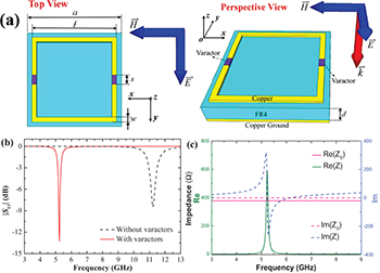
Fig. 1: (Colour online) (a) Proposed unit cell with two varactors under TE wave illumination. (b) Simulated reflection coefficient of SSLs with and without varactors for incident TE wave, where  ,
,  ,
,  ,
,  , and
, and  . (c) Free-space impedance
  and the effective impedance of SSL with two capacitances of 2.35 pF (Z).
Download figure:
Standard imagePhysics of varactors-loaded SSLs
In order to demonstrate the effects of varactors, we compare the reflection coefficient  of SSLs with and without varactors, as shown in fig. 1(b). A typical SSL without varactors has a minimum reflection coefficient of −8.45 dB at 11.23 GHz, which indicates its resonant frequency. When two zero-bias varactors with the capacitance value of 2.35 pF are located on the splits of SSL, the resonant dip shifts to a much lower frequency around 5.24 GHz with a reflection coefficient up to −13.26 dB. These results can be explained by analyzing the impedance of the structure in fig. 1(c) and extracting an equivalent circuit model for metamaterial absorbers under normal incidence, as shown in fig. 2(a). The characteristic impedance of the free space is
  , where
  and
and  are the permittivity and permeability of the free space, respectively. The metamaterial absorber exhibits the frequency-dependent permittivity
  and permeability
  under effective medium approximations [17], and its input impedance in the circuit is determined by
  . When
  is approximately matched with Z0 at about 5.24 GHz, as shown in fig. 1(c), the metamaterial absorber achieves the minimum reflection to the incident wave, and the maximum microwave absorption is reached since transmission is blocked by use of a copper short-circuit ground plane. In this circumstance, the input impedance of the grounded FR4 layer behaves as an equivalent inductor Ld because its thickness is much smaller than a quarter of wavelength [18]. The resonant property of the absorber is attributed to the resonance of an RLC loop in the circuit, where R, L, and C are the equivalent resistor, inductance, and capacitance of the SSL. The resonant frequency of the RLC loop is determined by the following equation:
where the capacitance C mainly depends on the size of the two splits. When the varactors are loaded on the splits, this implies connecting a capacitor in parallel (neglecting other parasitic circuit parameters), which increases the total capacitance in the circuit and lowers the resonant frequency significantly. Additionally, the introduction of the varactor capacitance brings about little change to the resistance in the circuit, but strengthens the capacity of the power storage, which leads to an increase of the quality factor compared to an SSL without varactors.
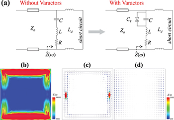
Fig. 2: (Colour online) (a) Equivalent circuit model for proposed metamaterial absorbers. (b) Electric-field distribution on top of the FR4 layer. Surface current distributions: on the square loop (c) and on the ground plane (d). The field and current distributions are for TE wave incidence at 5.24 GHz.
Download figure:
Standard imageNext, we further reveal the absorption mechanism from the view of electromagnetic fields. At the frequency where the absorption reaches a maximum, the incident electric field strongly couples with the copper loop's sides that are parallel to the electric-field component of the incident wave and excites an independent electric dipole response as shown in fig. 2(b). The surface charge oscillates along the sides excited by the external electric field. Figure 2(c) and (d) demonstrate that the incident wave generates an antiparallel surface current on the loop and the copper ground, which leads to magnetic coupling and the magnetic dipole response. The magnetic dipole is guided in the FR4 layer between each loop and the copper ground. Based on the analysis of the electromagnetic field [19], the microwave absorption originates from the superposition of inverse microwave field components that are induced by the electric dipole of the copper loop and the magnetic dipole generated in the FR4 layer, respectively. Moreover, in view of the actual materials in the structure, the microwave absorption arises from both the dielectric loss of FR4 and the ohmic loss on the copper loop due to the interaction of the electric field in these materials [20]. It is also observed in fig. 2(c) that the surface current density across the varactors is dramatically the largest on the square loop, which indicates the significance of varactors for tuning microwave resonant properties. This result demonstrates that the use of varactors makes the copper loop conductive and increases its effective electrical length for lower microwave frequency applications, and implies that one can tune the capacitance values of the varactors electrically in order to further steer the electromagnetic response of the metamaterial absorbers.
Computational simulations of varactors-loaded SSLs
After revealing the physical insight of loading varactors on SSLs, we investigate the influence of tuning capacitance value of varactors. In this study we implement Skyworks SMV 1231 varactors, which have a capacitance determined by the following equation:

where VR is the reverse bias voltage,  is the zero bias capacitance,
  is the gradient coefficient of the varactor, and
  is the intrinsic potential. In practice, when the varactors are mounted on the splits of SSLs, a parasitic inductor LV and a parasitic resistor RV are also inevitably introduced in the high-frequency circuit due to the use of boding wires. Taking account of these factors in electromagnetic simulations, we assume that the use of varactors bring about three serial lumped elements: LV, RV and a tunable capacitance CV. The resonant properties of varactor-loaded SSLs mainly depend on CV, and LV influences the resonant frequency slightly. The quality factor of varactor-loaded SSL resonators severely depends on RV, and it drops as RV increases (not shown here). Figure 3 shows the simulated reflection coefficient as a function of the varactor capacitance, where a relatively small LV of 0.23 nH and a series RV of 4.3Ω are assumed. It is observed that the resonant frequency shifts from 5.12 GHz to 5.67 GHz as the capacitance value decreases from 2.18 pF to 0.56 pF. Additionally, the reflection coefficient becomes smaller (from −10.11 to −17.71 dB) as the capacitance value is reduced, which means the appropriate reduction of the varactor capacitance value for the proposed metamaterial absorber can effectively enhance the absorption efficiency.

Fig. 3: (Colour online) Simulated reflection coefficient of varactor-loaded SSLs, where  ,
,  ,
,  ,
,  ,
,  , and CV, LV and RV are assumed as lumped elements.
Download figure:
Standard imageExperiments of varactors-loaded SSLs
In order to show the effectiveness and feasibility of the proposed unit cells, an experimental characterization of the tunable metamaterial absorber is performed using a rectangular waveguide system and an Agilent network analyzer (10 MHz–20 GHz), which have been widely used to measure the transmission and reflection of microwave metamaterials [21–23]. In the measurements, the planar metamaterial absorber is attached to the open end of a WR187 waveguide which operates from 3.95 GHz to 5.85 GHz, and it allows us to measure a prototype with only a few unit cells [24]. The microwave absorber consists of an array of 4 × 2 varactor-loaded SSLs on a thin (0.8 mm) FR4 grounded substrate, and neighboring SSLs are connected using two high value resistors of 10 kΩ, as shown in the front side of fig. 4(a). The copper ground is connected with the walls of the waveguide in measurement. The DC feeding lines for applying reverse bias voltages are connected through four via holes on a thin FR4 substrate (0.8 mm) which is placed behind the ground plane, and a choke resistance of 10 kΩ is used for every feeding line, as shown in the back side of fig. 4(a).
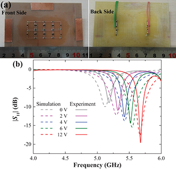
Fig. 4: (Colour online) (a) Photographs of a typical manufactured sample, where the varactors and 10 kΩ resistors are vertical and parallel to the ruler, respectively. (b) Measured and simulated reflection coefficients for various voltages on the feeding network, for  ,
,  ,
,  ,
,  , and
, and  .
.
Download figure:
Standard imageIt is observed from fig. 4(b) that the resonant frequency shifts from 5.18 to 5.68 GHz, as the voltage on the feeding network changes from 0 V to 12 V, because the capacitance value of the loaded varactors increases as the applied voltage increases. Upon increasing voltages above 10 V, the reflection spectra change slightly, because further increase of the applied voltages brings about little change to the capacitance value of the varactors according to eq. (2). Moreover, as the capacitance value is reduced by raising the applied voltage, the reflection coefficient becomes smaller (from −8.90 to −19.57 dB), which means achieving a high-quality factor of the absorber. The measured bandwidth of absorption is a little smaller than the simulation, and this difference might be attributed to the use of infinite boundary conditions for unit cells in simulation. Generally speaking, the experimental results indicate good agreement with the simulation results, and demonstrate a tuning range of 0.5 GHz for the resonant frequency. The experimental work also implies that the functions of the active structure can be switched between absorption and reflection for a fixed frequency. For instance, at a frequency of 5.68 GHz  is −0.378 dB for the voltage of 0 V, whereas
  turns to be −19.57 dB when the voltage is switched to 12 V.
Absorption tolerance of oblique incidence on varactor-loaded SSLs
The discussion above is based on a normal incident wave, but in many application environments metamaterial absorbers should ensure high microwave absorption efficiency for a wide range of wave incident angles. Based on this consideration, we demonstrate the absorptivity for the proposed unit cells as a function of microwave frequency and incident angle, as shown in fig. 5. Since we do not use magnetic materials in the structure, the physical mechanism can be illuminated only in consideration of the effect of the external electric-field components.
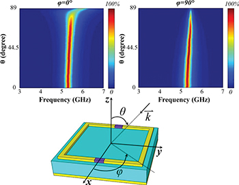
Fig. 5: (Colour online) Simulated absorptivity of the metamaterial absorber with 2.0 pF varactors as a function of the frequency and incident angle. When  , the excitation is a TE wave. The colour bars denote the percentage of absorptivity.
Download figure:
Standard imageWhen the incidence azimuth  , the electric-field component is parallel to the copper loop's sides where the varactors are located, so the resonant frequency is only slightly changed for a large variation of the incident angle θ, and an absorptivity higher than 80% is achieved even for a large incident angle up to 70°. When
  , the electric-field component applied on the unit cells can be resolved into Ey and Ez, which are electric-field vectors parallel to the copper loop's sides with varactors and perpendicular to the copper ground plane, respectively. Based on the above-mentioned equivalent circuit analysis, the circuit elements generated by Ey are the same as in fig. 2(a), and the effects of Ez introduce an additional capacitance Cz between the square loop and the ground plane due to the high-frequency alternate electric field in the z-direction. Cz is much larger than CV, but the series of Cz and CV reduces the total capacitance of the RLC loop slightly, which results in a slight shift of resonance to higher frequencies according to eq. (1). In general, the varactor-loaded metamaterial absorbers possess high absorption efficiency for a wide range of incident angles.
Potential applications of multiple concentric SSLs with varactors
Finally, based on the study of a single SSL in a unit cell, we evaluate the application of multiple concentric metallic loops in a unit cell for multiple absorption bands. The structure using three concentric metallic loops with varactors in a unit cell is simulated as shown in fig. 6. The three loops have the same metallic line width of 0.5 mm and the same split width of 1 mm, and the neighboring loops are 0.5 mm apart from each other as shown in fig. 6(a). The outer side lengths of three loops are 9 mm, 7 mm and 5 mm, respectively. It can been seen from fig. 6(b) and fig. 6(c) that the metamaterial absorber shows three absorption bands due to the use of multiple loops and these absorption bands are electrically tunable by controlling the capacitance values of varactors for every metallic loop.

Fig. 6: (Colour online) (a) Top view of three concentric metallic loops with varactors, where C1, C2 and C3 represent the capacitance values of loaded varactors. (b) Simulated reflection coefficient for normal incident TE wave as a function of tunable capacitance in varactors.
Download figure:
Standard imageThe active metamaterial absorber working on multiple absorption bands can be used for the composite coding in combination with digital signals and microwave frequency-domain signals. In the future work, the experimental work in view of the design of a feeding network and digital coding will be performed in order to further expand applications of varactor-loaded SSLs in RFID and telecommunication.
Conclusion
In summary, we have investigated a type of tunable microwave metamaterial absorbers by using varactors in a metal-dielectric-metal structure. We systematically demonstrated the design principles of using varactor-loaded copper square loops from the viewpoint of an equivalent circuit and electromagnetic-field analysis. The thin planar structure with a simple back feeding network is flexible and scalable for the development of multiple loops in a unit cell. Our achievements provide a guide for using varactors to design active metamaterial absorbers and imply a great potential of varactor-loaded metamaterial absorbers for wide microwave applications.
Acknowledgments
This work was supported by the National Natural Science Foundation of China (NSFC Grant Nos. 61307042 and 41390453) and the Fundamental Research Funds for the Central Universities.