


Abstract
A novel class of low-frequency sound absorbers based on a honeycomb sandwich panel is theoretically designed and numerically demonstrated. The absorber with a remarkably small thickness (e.g., 1/131 of wavelength) is comprised of a perforated facesheet, a perforated honeycomb core and a non-perforated back panel. Built upon the classical microperforated panel absorber (MPPA), the idea of introducing a perforated honeycomb core which creates a double-layer perforated absorber (DLPA) without adding to the total thickness greatly enhances the low-frequency absorption performance. Theoretical predictions of the sound absorption coefficient are obtained and compared with numerical simulations obtained using the finite element method (FEM). A good agreement is achieved. The proposed sound absorber is promising for low-frequency noise absorption especially when limited space and high mechanical stiffness/strength are simultaneously demanded.
Export citation and abstract BibTeX RIS
Low-frequency sound attenuation by absorbers with deep-subwavelength scales has great engineering significance but remains challenging to achieve especially when the space available is restricted. Researches about absorbers consisted of rigid porous lattices can achieve perfect and broadband absorption at low frequencies [1–4]. However, with thicknesses almost equal to the wavelength of incident sound, these lattice-based absorbers are way too thick. Recently, increasing the propagating path of the sound wave and introducing a non-rigid structural resonance have been found effective in realizing better low-frequency absorption with thinner constructions. For instance, based on the Helmholtz resonance [5–7], micro-scale structure or device [8,9], or membrane-type resonator [10,11], innovative structures and materials having millimeter-scale thicknesses can reach perfect absorption at a few hundred hertz. With submillimeter thickness, the elastic membrane can even be designed to achieve a good absorption at 170 Hz [12], though not a perfect absorption. Thus far, however, existing researches have all focused on absorbers with thin but complicated constructions. The theoretical realization and numerical validation about a low-frequency sound absorber with subwavelength thickness based on simple yet widely available load-carrying structural members remain elusive.
In this letter, based on the honeycomb sandwich structure and inspired by the Helmholtz resonance, we present a novel class of ultra-low–frequency absorbers with deep-subwavelength thickness. The new absorber comprises a perforated thin facesheet, a perforated square honeycomb core, and a non-perforated back panel. Perfect sound absorption could be achieved at an extremely low frequency while the total thickness of the sandwich absorber is less than one percent of the sound wavelength. Further, with millimeter perforations, the novel sandwich absorber is ultra-lightweight and possesses excellent mechanical properties such as stiffness, strength and energy absorption, thus perfect for multifunctional applications requiring simultaneous ultra-low–frequency sound absorption and load-bearing.
The proposed sandwich absorber is sketched in fig. 1(a), which is made up of many similar units as shown in fig. 1(b). One of its facesheets is perforated to form, together with the honeycomb cavity behind it, a resonant absorber. Meanwhile, the honeycomb wall is also perforated, so as to establish a DLPA [13,14] in a space-saving manner. The total thickness of the DLPA can be considerably small if its second layer is set up in this way, which helps to reduce the scale when designing low-frequency absorbers. The back panel is considered to be rigid when studying the absorption performance of the whole structure. For this purpose, the back panel should not be too thin.
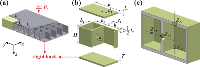
Fig. 1: (Color online) (a) The sketch of sound absorptive panel with arrays of quadrilateral honeycomb sandwich structures. (b) A unit cell, with cross-sectional area  , composed of a facesheet (thickness t1) with a circular hole (diameter d1), a honeycomb (thickness H) with a circular hole (diameter d2) on one of its vertical walls (thickness t2) and a back panel (thickness T). (c) Cross-sectional view of a unit. The circuit demonstrates the analogy between the structure of the absorber and the inner impedance relationship.
Download figure:
Standard imageIn general, the absorption coefficient of an absorber represents the ratio of dissipated acoustic energy to incident acoustic energy. For an absorber with rigid backing, it has a close relationship with the relative surface impedance, expressed as

in which  . Zs refers to the surface impedance of the absorber at the incident plane, while
  refers to the characteristic impedance of air,
  and c0 being the mass density and the speed of sound in air, respectively. From eq. (1) we know that when the real part of the relative impedance
  and the imaginary part of the relative impedance
  , perfect absorption of the incident sound is realized. Actually, air in the perforations will oscillate severely because of the resonance at and around the perfect absorption frequency, causing a great kinetic energy loss of the air. Thus, the acoustic energy will be intensely absorbed at the resonance frequency [15,16].
The proposed absorber of fig. 1 may be theoretically processed to become a DLPA, if the perforated facesheet and the perforated honeycomb wall are visualized as a perforated panel of the first layer and the second layer, respectively. Accordingly, the impedance of the n-th  layer can be obtained by applying the theory of DLPA [17,18], as

with

where  when n = 2. As shown in fig. 1(b), the two cavities have thicknesses
  and
and  . The area modification factor
  in eq. (2) satisfies: i)
  and ii)
  when n > 1, which is introduced based on the parallel assembly theory of sound absorbers [19,20]. The panel impedance ZPn and the cavity impedance ZCn can be derived separately from eqs. (3) and (4), in which (pn, tn, dn, Dn) denote the porosity, the panel thickness, the perforation diameter and the cavity thickness of the n-th layer. Among them the porosities are not directly given or measured, but rather described as i)
  and ii)
  when n > 1. These four major parameters have much influence on the absorption performance of the absorber, and their different combinations usually lead to different usage scenarios [21–23]. In the equations above, j denotes the imaginary unit and ω represents the angular frequency of sound.
  represents the ratio of the perforation diameter to the thickness of the viscous boundary layer, in which η stands for the dynamic viscosity.
  is the wave number in the air. Besides
  , the surface area modification factor
  should be considered as the impedance revision of the incident plane. In consequence, the surface impedance can be obtained as

To obtain FEM results of the absorption spectrum, the acoustic-thermoacoustic interaction is performed in the frequency domain with COMSOL multiphysics. Energy dissipations of the medium caused by viscous resistance and thermal conduction are taken into consideration by using thermoacoustic physics, while the honeycomb walls and the back panel are both regarded as rigid boundaries. A normally incident plane wave propagating along the z-axis is considered to evaluate the surface impedance of the absorber. The medium in and around the absorber is air, with mass density  , sound speed
  , and dynamic viscosity η of
  .
.
Figure 2 demonstrates the low-frequency absorption coefficient and relative impedance of the present absorber with a total thickness of  . Overall, for the frequency range considered, the theoretical predictions agree well with the FEM results. In fig. 2(a), nearly perfect absorption (0.996) is realized at 136.6 Hz, the wavelength of which is 131 times the absorber's total thickness, demonstrating the brilliant low-frequency sound absorbing property of the proposed absorber. To explore the underlying physical mechanisms, the theoretically predicted relative impedance of the same absorber is shown in fig. 2(b). Relative impedance denotes the normalized surface impedance, which can be utilized to calculate the sound absorption coefficient from eq. (1). Their relationship illustrates that perfect absorption can be attained when impedance matching is achieved between the absorber and air. The resistance, namely the real part of the impedance
  , equals to one at 108.1 Hz, while the reactance, namely the imaginary part of the impedance, crosses the zero line at 136.6 Hz. So the resistance and the reactance of the absorber cannot meet the impedance matching condition at the same frequency. As a result, perfect absorption of
  will not be achieved. Instead, the maximal absorption of
  happens at 136.6 Hz in this study. On the other hand, the magnitude of the resistance is much smaller than that of the reactance, on account of the relatively big perforation diameter (a few millimeters) required for low-frequency absorption. Therefore, the resistance is the dominant parameter affecting the absorption performance of the perforated sandwich panel absorber. Under such circumstances, the absorption coefficient has a peak at the frequency where the reactance is zero, rather than at the frequency where the resistance is unity.
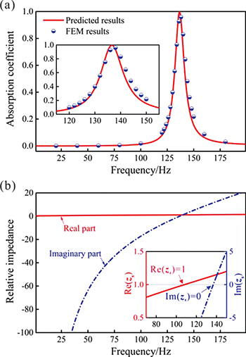
Fig. 2: (Color online) (a) Sound absorption vs. frequency curves obtained from theoretical analysis (red line) and FEM (blue circles) for a perforated sandwich absorber with dimensions  ,
,  ,
,  ,
,  ,
,  ,
,  ,
,  ,
,  and
and  . (b) Normalized relative impedance of the absorber. The real part is denoted by the red solid line and the imaginary part by the blue dashed line.
Download figure:
Standard imageTo demonstrate the superiority of adding perforation to the honeycomb wall, fig. 3 compares the sound absorption performance of the absorber having a perforated honeycomb (APH) with the conventional perforated absorber (CPA). Again, a good agreement between theory and FEM is achieved. For the two absorbers considered in fig. 3, APH exhibits perfect absorption (1.0) at 284 Hz, whereas the best absorption (0.989) of CPA is achieved at 319 Hz: the low-frequency absorption performance is apparently enhanced by the addition of the perforated honeycomb, as the enhancement of shifting the absorption peak from high to low frequency is 10.9%. Compared with APH, CPA has a slightly wider bandwidth for its bigger cavity and a smaller area modification. By creating a second layer with the perforated honeycomb core, the APH (total thickness unchanged) sacrifices a bit the bandwidth for much better low-frequency performance.
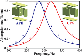
Fig. 3: (Color online) The absorption coefficient of a quadrilateral honeycomb sandwich absorber with perforated top facesheet The blue line and the red line illustrate the theoretically predicted absorption curve of APH and CPA, while the blue squares and the red circles represent the FEM results of APH and CPA, respectively. Dimensions of the absorber:  ,
,  ,
,  ,
,  ,
,  ,
,  ,
,  ,
,  and
and  .
.
Download figure:
Standard imageUpon introducing a new resonant domain by perforating the honeycomb core, the first absorption peak is considerably affected. Actually, at low frequencies, this new resonator alone behaves worse than the original resonator because of its narrow cavity thickness. Even so, forming a DLPA by combining the two resonators adds new path to sound propagation, thus lowering the frequency of the absorption peak. Moreover, while bringing in more layers will likely improve further the low-frequency absorption property of the absorber, the corresponding configuration will be more complicated. Also, perforated absorbers with three or more layers lead to much less enhancement in sound absorption than those with two layers.
We investigate next the influence of three geometrical dimensions, t1, d1 and H, on the absorption performance. Figure 4(a) shows the sound absorption spectrum as a function of the facesheet thickness t1, with other dimensions unchanged. When the facesheet thickness is increased, perfect absorption gradually moves from higher frequencies to lower ones, with the bandwidth almost unaffected. The reactance becomes larger with increasing facesheet thickness, pushing the impedance matching to lower frequencies. As a result, the absorption peak is achieved at a lower frequency. Figure 4(b) illustrates the variation of the sound absorption spectrum with the facesheet perforation diameter d1. It is easy to reduce the peak frequency by reducing the perforation diameter. However, simultaneously, perfect absorption as well as a relatively broader bandwidth will be hard to attain. Broadband absorption in an intermediate frequency range calls for absorbers with small perforations, or micro-perforated absorbers [23]. When it comes to low frequencies, this principle is apparently not applicable. Figure 4(c) reveals the relationship between the sound absorption spectrum and the honeycomb thickness. As a matter of fact, the trend is almost the same as that of the facesheet thickness. The total thickness always plays significant role in sound absorption, for thicker absorbers have greater potential in dissipating low-frequency sound [24]. As a consequence, it is a dilemma whether to select a thinner configuration or to choose a better low-frequency absorption performance, when an absorber with a bigger ratio of sound wavelength and structure thickness is required. Prolonging the path of the sound wave without adding to the thickness of the absorber is an effective and innovative way [5,6,25–32], as is adopted in the current study. Besides, judging from the results of fig. 4, a promising perspective is the probability to fulfill an even lower-frequency perfect absorption by diminishing the perforation size and raising the total thickness. In fact, it is likely to accomplish perfect absorption at just dozens of hertz with structural members having jumbo sizes.
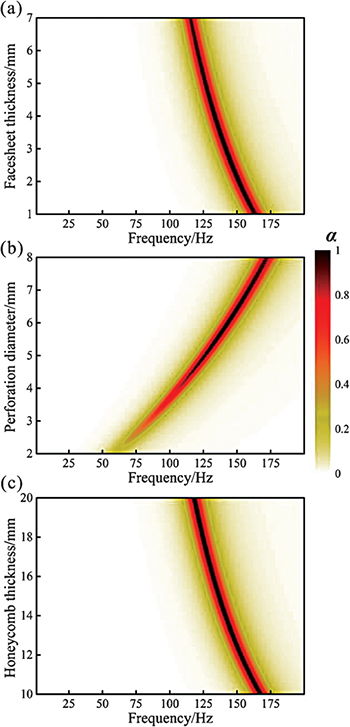
Fig. 4: (Color online) Sound absorption spectrum below 200 Hz plotted as a function of (a) facesheet thickness, (b) perforation diameter and (c) honeycomb thickness. Other dimensions:  ,
,  ,
,  ,
,  ,
,  ,
,  ,
,  ,
,  and
and  when these are not studied as variation parameters.
Download figure:
Standard imageIn conclusion, based on traditional honeycomb structures, low-frequency sandwich panel absorbers with deep-subwavelength scale have been theoretically designed and numerically demonstrated. By perforating both the face-sheet and the honeycomb wall, the proposed sandwich absorber with a total thickness of 19.1 mm is able to fully dissipate the incident energy of sound at 136.6 Hz, whose wavelength is 131 times larger than the absorber's thickness. The advantage of perforation and the mechanism underlying the enhanced dissipation of sound energy are investigated, and it is demonstrated that perforating the honeycomb wall leads to an apparent decrease in the perfect absorption frequency. The proposed honeycomb sandwich absorbers cannot only overcome difficulties in achieving low-frequency sound absorption with traditional jumbo-sized acoustic members, but they also are promising multifunctional lightweight materials/structures for simultaneous mechanical load-bearing and sound absorption.
Acknowledgments
This work was supported by the National Natural Science Foundation of China (51528501) and the Fundamental Research Funds for Central Universities (2014qngz12).