

Abstract
In this letter, an MFC/brass/NdFeB tip magnet three-phase cantilever beam was coupled with a pair of movable magnets to harness energy from alternating magnetic fields. By coupling with a pair of moveable magnets, both bandwidth and magnetoelectric (ME) voltage coefficient  were largely increased by 25% and 87.5%, respectively, in comparison with the same harvester coupled with stationary magnets. Such improvements were attributed to magnetic energy introduced by the moving magnets. Experiments also revealed the boundary positions of external magnets (movable and stationary) where the repulsive magnetic forces jumped to the attractive ones, and the stiffness hardening switched to the softening process. These results provided a wide-band nonlinear approach to efficiently harvest/detect the low-frequency alternating magnetic field energies.
Export citation and abstract BibTeX RIS
Introduction
The giant magnetoelectric (ME) effect which was discovered in magnetostrictive/piezoelectric laminated composites has been extensively studied in recent years [1]. In particular, the ME effect, referring to induced electrical polarization in response to the magnetic field, finds lots of engineering applications in energy harvesting by applying an external electric/magnetic field between these two phases (layers) via the strain/stress coupling [1,2]. For real world applications, there are many magnetic flux leakages that can be harvested, such as those from electric transmission overhead lines, unmanned undersea vehicles, and buoys in the sea [3,4]. The efforts to disseminate the use of the ME devices to improve the energy harvesting performance involve both enlarging the magnitude of the output voltage and widening the operation bandwidth (BW) [5]. In the past, a popular strategy to achieve this often relies on more efficient transduction materials (e.g., Terfenol-D, Metglas, etc. in the magnetostrictive phase and PZT, PMN-PT, etc. in the piezoelectric phase) with optimized mechanical configurations. For instance, a PMN-PT/Metglas laminate was reported with a high ME coupling coefficient 52 V/cm−1 Oe−1 at non-resonance [6] and a PZT/brass-sheet composite beam with NdFeB magnets was simulated with an ME coupling coefficient of 92 V/cm−1 Oe−1 at quasi-static condition under an applied longitudinal magnetic field [3].
However, most conventional magnetoelectric devices were designed to operate at a single resonant frequency which limits their operating bandwidth. A slight frequency mismatch will significantly reduce its transduction efficiency. To overcome this disadvantage, energy harvesting devices with tunable resonances have been designed in the literature, based on the intrinsic nonlinearity in stiffness softening and hardening processes, and thus the bandwidth of the operational frequency will be widened [7–15]. For instance, the bandwidth-widening was achieved by combining a series of ME composite structures in parallel and in series [16] or by tuning the stiffness of the PZT substrates with external electrical fields [17]. However, their fundamental resonant frequencies were still quite high, their bandwidths were still relatively narrow and the off-resonance voltage output still drops significantly. At last, all the aforementioned works on ME devices focus on vibrational energy harvesting and very limited work was reported on magnetic field energy harvesting and its performance improving strategies.
A typical bandwidth-widening strategy for piezoelectric vibrational energy harvesting is to soften the piezofiber/magnet structure with coupled external magnets at stationary positions, so that the fundamental resonance frequency  can be lowered and the effective resonance bandwidth can be expanded [10–15,18–20]. By introducing this strategy to magnetic field energy harvesting and extending this concept by using a pair of movable magnets, in this letter, we demonstrated that a three-phase piezofiber/brass/NdFeB magnet composite cantilever exhibits a largely broadened bandwidth and an improved power output performance via the strong magnetic coupling force between the tip magnet of the three-phase cantilever and the moveable magnets attached to a brass cantilever beam. The tunable peak resonance response originated from the fundamental resonance of the three-phase composite cantilever and the coupled magnetic force between its tip magnet and the movable magnet pair. An enhancement in the power output and the ME effect outperforms their counterparts with a pair of stationary magnets, which both outperform the conventional ME composite energy harvesting devices.
Structure and working principle
Figure 1 shows the schematic and photographic representation of the low-frequency broadband ME energy harvesting devices namely: ME Device 1 (with a pair of external stationary magnets) and ME Device 2 (with a pair of external moveable magnets). For both devices, the active components were a three-phase piezofiber/brass/NdFeB magnet composite cantilever made of a brass substrate, a microfiber composite (MFC) piezoelectric patch, and a pair of NdFeB tip magnets. The MFC, with the dimension of  , was constructed by Smart Material Corporation and then bonded to the clamped end of the brass substrate
  . Then, a pair of N42-type NdFeB magnets from K&J Magnetics
  with the perpendicular magnetization direction were bonded at the free end of the brass beam.
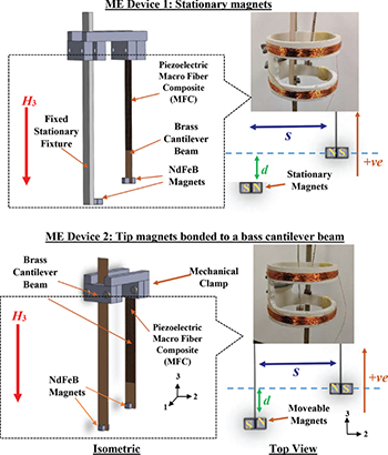
Fig. 1: (Colour online) Schematic diagram and photographic representation of the proposed ME devices in the Cartesian coordinate system.
Download figure:
Standard imageME Device 1 was made to prove the outperformance of the ME Device 2. In order to make a fair comparison, the cantilever beams and the tip magnets of both ME devices (ME Device 1 and 2) have identical configurations. For ME Device 1, two NdFeB magnets with the same dimensions but in the opposite magnetization direction to the tip magnets on the three-phase composite cantilever beam, were bonded and fixed on the stationary mechanical fixture which would then provide a stable magnetic field coupling and force. However, for ME Device 2, two of the same type magnets were bonded at the free end of another  brass beam, which was clamped with the same fixture in the opposite magnetization to the tip magnets on the three-phase cantilever to form a moveable magnetic array to provide a dynamic magnetic coupling force.
The working principle of the two ME devices 1 and 2 (fig. 1) is described as follows. An AC magnetic field (H3) applied along the longitudinal direction (vertical direction in fig. 1) of the ME devices induced the vibration of the external NdFeB magnets, which produced an alternating magnetic moment that actuated the tip magnets on the free end of the composite cantilever and then subsequently creates a bending motion. The bending stress and strain were then elastically coupled to the MFC piezoelectric patch, which produced a magnetoelectric voltage output  via an electromechanical coupling. The magnetoelectric voltage coefficient
  was found by the relationship of
  and
and  . The magnetization direction of the external magnets (stationary for ME Device 1 and moveable for ME Device 2) was in the opposite direction to that of the tip magnets of their corresponding three-phase composite cantilever. Such a magnetization reversal leads to a repulsive magnetic force when the vertical height (d) between these magnet counterparts is relatively small. However, such a repulsive magnetic force jumps to an attractive force when d becomes larger than a certain threshold value. This threshold value depends on the horizontal distance (s) of the tip magnets and their counterparts as well. Here, the difference between ME Device 1 and 2 was stated as follows: For ME Device 1, the external magnets were bonded to the mechanical stationary fixture, therefore no external alternating forces will be produced by the magnets. However, for ME Device 2, the two-phase cantilever with moveable magnets vibrates in an out-of-phase bending direction relative to its three-phase cantilever counterpart under the same applied magnetic field H3 due to the reversed magnetization of the NdFeB magnets. Such a configuration has made a breakthrough to enhance the external attractive force to soften the structural stiffness towards its extreme. As a result, an enlarged magnetic coupling force and a giant
  was obtained in the ME Device 2.
Results and discussion
Figure 2 shows the measured  of the ME Device 1 installed at
  with the range of d from −30 mm to +30 mm driven by the constant H3 with a peak of 3 Oe in the frequency range of 1–20 Hz under (a) upward and (b) downward frequency sweeps. A measurement of single three-phase composite cantilever without external magnets was also plotted in the same figure for analytical purposes. It clearly shows that the structural stiffness was hardened (the resonance frequency
  was increased) within a range when d was between −15 mm to +20 mm in the upward frequency sweep and was between −10 mm to +20 mm in the downward frequency sweep. In this range, the repulsive forces were produced between the tip magnets of the three-phase cantilever and the external magnets (stationary) which restrained the bending of the three-phase cantilever that made the resonance frequency increasing. Beyond this region, the decreased
  was obtained due to the stiffness softening and the coupling forces between the two coupling magnets that were altered from repulsive to attractive forces. Beforehand, the resonance frequency
  , bandwidth (BW), and the resonance magnetoelectric voltage coefficient
  of a single three-phase composite cantilever were determined to be 9.8 Hz, 0.55 Hz, and 11.2 V/Oe, respectively, in both the upward and downward frequency sweeps. By setting
  , the repulsive force of the two identical NdFeB magnet pairs was changed to the maximum attractive force of the ME device which provided an extra attractive force acting on the tip magnets of the three-phase composite cantilever and decreased the
  to 6.6 Hz in the downward frequency sweeps and also enhanced the bandwidth to 1.9 Hz. However, the
  was reduced to 10.8 V/Oe.
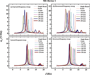
Fig. 2: (Colour online) Measured  of our proposed ME Device 1 mounted at
  driven by a constant H3 of 3 Oe peak in the f range of 1–20 Hz and in the d range of −30–30 mm under (a) upward and (b) downward frequency sweeps.
Download figure:
Standard imageFigure 3 illustrates the measured  of our proposed ME Device 2 installed at
  with the same parametric ranges of d and
  that applied to the ME Device 1 (fig. 2) under the (a) upward and (b) downward frequency sweep. Note that the measurement of the case for
  and −25 mm could not be performed because the extremely strong attractive force stacked these magnets together and obstructed the bending motion during attempted measurement. By setting
  , the maximum
  of 22.5 V/Oe was found. By setting
  , the maximum bandwidth of 2.5 Hz was reached, which was much larger than that produced by the external stationary magnets of the ME Device 1. The bending of the two cantilevers (three-phase and two-phase composite cantilever) were operated in an opposite bending direction due to the reversed magnetization direction of the two pairs of NdFeB magnets, which decreased the
  of the three-phase cantilever from 9.8 Hz to 5 Hz, but widened the bandwidth to 2.5 Hz. This also proved the outperformance of ME Device 2 by 48% (9.8 to 5 Hz) for stiffness softening, 350% for bandwidth widening (0.55 to 2.5 Hz) and 100% (11.2 to 22.5 V/Oe) for ME voltage coefficient increasing compared with single ME composite beam.
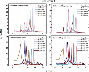
Fig. 3: (Colour online) Measured  of our proposed ME Device 2 mounted at
  driven by a constant H3 of 3 Oe peak in the f range of 1–20 Hz and in the d range of −30–30 mm under (a) upward and (b) downward frequency sweeps.
Download figure:
Standard imageTo further compare the performance of both ME devices (ME Device 1 and 2), the calculated BW based on the half power point (−3 dB) plotted at different values of d were evaluated to construct the parametric dependence study of d. Figures 4 and 5 show the  ,
,  , and BW against the d of the ME Device 1 and 2 operated at (a) upward and (b) downward frequency sweep, respectively. All the corresponding data were calculated and extracted from figs. 2 and 3. For the ME Device 1 (fig. 4), two important observations were obtained. First, almost all
  were lower than those of the single three-phase cantilever composite. Second, the wider bandwidth was only obtained while d was lower than −10 mm especially when d was equal to −15 mm during the downward frequency sweep. These observations can be explained by the use of a larger value of vertical separation between the stationary magnets and their tip magnet counterpart attached to the three-phase cantilever, which in turn weakens the magnetic force interaction. For the ME Device 2 (fig. 5), the measured results were entirely opposite to those of the ME Device 1. First, almost all the values of
  were larger than those of the single three-phase cantilever. Second, the broader bandwidth could be obtained when d is less than −15 mm or greater than 15 mm. Specially, when d was set at +20 mm, the broad bandwidth was obtained in both the upward and the downward frequency sweeps. These results suggested that the nonlinear phenomena induced by moveable external magnets outperforms that produced by stationary external magnets. And therefore, such a configuration offers a promising solution for largely increasing the wide bandwidth and improves the power harvesting efficiency in comparison to that which uses stationary external magnets and that which uses a single resonance ME composite.

Fig. 4: (Colour online)  , and BW dependence on d of our proposed ME Device 1 operating at (a) upward and (b) downward frequency sweep extracted from fig. 2.
Download figure:
Standard image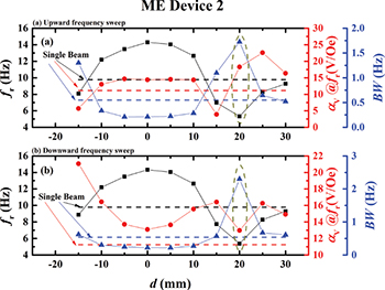
Fig. 5: (Colour online)  , and BW dependence on d of our proposed ME Device 2 operating at (a) upward and (b) downward frequency sweep extracted from fig. 3.
Download figure:
Standard imageTypically, by introducing the nonlinear effect, the bandwidth will be increased with the decreased ME coupling coefficients, which can be observed from ME Device 1. However, both the bandwidth and the ME coupling efficient were found improved for ME Device 2, by 350% and 100% respectively, due to superior nonlinear phenomena of movable magnets than stationary ones. More specifically, by making the magnets on the two-phase cantilever movable, the additional bending moment of the two-phase cantilever will strength the AC magnetic field under specified magnet positions, which in turn, will be transferred to three-phase cantilever through tip magnet interactions and result in larger excitations of the three-phase cantilever.
In order to determine the optimal load resistance where the power output  of the ME Device 2 reaches its maximum, different resistive loads
  were connected to the output of the three-phase composite and tested under
  . Figure 6 shows the measured
  under different
  when the ME Device 2 was located at
  and
and  . The
. The  was strongly dependent on
  and the maximum
  was
was  at a resonance value of 1 MΩ. Here, a
  passive voltage probe with an internal load resistance of 10 MΩ was applied in the test due to the high internal resistance of the piezoelectric materials.
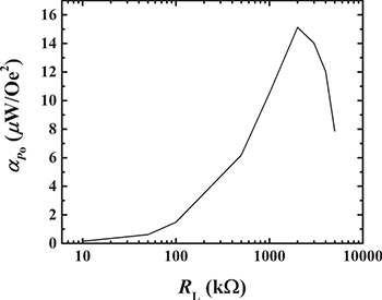
Fig. 6: Measured  of our proposed ME Device 2 mounted at
  and
and  driven by a constant H3 of 3 Oe peak at
  .
.
Download figure:
Standard imageConclusion
In summary, we have developed and characterized two promising nonlinear ME devices (ME Device 1 and 2) with widened bandwidth and lowered frequency resonance, attributed to the external magnetic force coupling between the tip magnets of the three-phase piezoelectric composite cantilever and its corresponding external stationary (ME Device 1) or moveable magnets (ME Device 2). The proposed ME devices, excited by alternating magnetic fields, have been experimentally studied and analyzed parametrically at different combinations of relative transverse distances and assembled heights. For the ME Device 1, the value of  was found at
  and
and  when operated under downward frequency sweep. For the ME Device 2, the values of
  ,
,  , and
, and  were found in the case of
  and
and  . The improved BW and
  were not only found in the upward frequency sweep frequency but also in the downward frequency sweep. In addition, frequency tunability was achieved by setting the different positions of the magnets. This is because of the force jumping between repulsive and attractive magnetic forces. Moreover, the resonance frequency can be adjusted when the length of cantilever beam changes. All these advantage features enable the promising application of magnetic energy harvesting and the bandpass filter, especially in low-frequency regions.
Acknowledgments
This work was supported by the U.S. Office of Navy Research (Award No. N000141410230), and the U.S. Department of Energy ARPA-E (Award No. DOE-AR0000531).