


Abstract
The Complimentary Split Ring Resonator (CSRR) is now popular in microwave devices. However, the analytical interpretations of its resonance frequencies, especially that with finite grounds, remains elusive. We demonstrate in this letter a novel method of unveiling the resonance mechanisms of antennas loaded with a finite-grounded CSRR (FG-CSRR) based on the equivalent circuit models. As a proof-of-concept, a triple-band antenna with FG-CSRR structure is explored, whose inner patch is loaded with additional elements with negligible impact on the inherent resonances of FG-CSRR. Various FG-CSRR-loaded antennas with different parameters are furthermore applied to validate our method. The proposed analytical model would facilitate the design of the operating mechanism of these antennas. Moreover, less metallic coating and the independent resonances of FG-CSRR promise its suitability for miniaturized microwave systems.
Export citation and abstract BibTeX RIS
Due to the exciting properties of the wave interaction with metamaterials, various novel antennas with desired properties have been inspired: compact [1–3], high-gain [2,4], broadband [4], multi-band [5], frequency-scanning [6], or even those with combined characteristics [2,4,7] and interdisciplinary functions [8] have been reported. A comprehensive review on the recent progresses on metamaterial-inspired antennas is given in [9]. However, the operating mechanisms of most reported antennas are not thoroughly explained with analytical models. One popular characterization method is to construct the equivalent circuit model. Yet, the circuit element values of most equivalent models are usually not determined in a reasonable physical manner by the geometrical dimensions of the antenna, but instead often numerically fitted given a circuit topology and its output response [1,6], e.g., scattering parameters.
Among the common antenna applications like indoor or vehicular communication, the split ring resonator (SRR) and its counterpart, the complementary split ring resonator (CSRR), are fairly common, in that these two designs of metamaterial unit cell intrinsically hold predictable resonance frequencies [10–13]. Still, their limitations are obvious. As for the CSRR, for instance, it requires infinite ground to achieve ideally "complementary" in theory. Furthermore, CSRR usually behaves resonantly at two frequencies, but the mechanism of the second resonant frequency is not so explicit as the first one. Hence, once finite grounds of CSRR are considered and both resonances are characterized to be efficiently predictable, the popularity of this structure would be generalized greatly.
In this letter, we focus on the CSRR structure with finite ground and propose an analytical model to predict its resonance frequencies. As a proof of concept, a CPW-fed triple-band multi-mode antenna loaded with finite-grounded CSRR (FG-CSRR) is analyzed in detail. Specifically, its equivalent models for the first and the second operating frequency bands are established to predict the resonant frequencies, and to help explain the corresponding operating modes. Measurement results are finally compared with the simulation ones to confirm our design and the presented equivalent models. Moreover, we apply the same models to other geometric parameters to qualify the proposed explicit expressions. To generalize our method, the resonance frequencies of several FG-CSRR-loaded antennas proposed in other researches are also calculated in our demonstrated approach. All the analysis and comparisons validate our analytical characterization of the FG-CSRR structure. Finally, it is demonstrated that the inner metallic patch of the proposed FG-CSRR antenna can be utilized to implement additional circuit elements or radiation structures without significant influence on the intrinsinc resonances of the FG-CSRR itself. Such a property makes it a good component for miniaturized microwave systems.
One of the important applications of FG-CSRR is to miniaturize the size of the radiator [1,14,15]. Without large area of the grounds needed, more structures can be loaded together with the FG-CSRR structure. We propose here a triple-band antenna composed of FG-CSRR and composite right/left-handed (CRLH) structures. The prototype of the proposed antenna is illustrated in fig. 1. The planar antenna structure is composed of the FG-CSRR formed by two outer square strips and an inner square patch, the CRLH structure constructed by an inter-digital capacitor on the inner square patch and vias electrically connecting the upper and bottom square patches. The substrate covers a volume of  and has a relative permittivity
  with loss tangent value being 0.0035. As shown in fig. 1(a), the FG-CSRR is realized by two C-shaped slots. The outermost square strip (of length a and strip width S1) is connected using one short stub with the inner square strip (of length b and strip width S2), forming one C-shaped slot. The inner square strip is then attached to the central square patch (of side length c) with another short stub (of width 0.8 mm), forming the other C-shaped slot. Furthermore, to take full advantage of the empty space on the central square patch, a CRLH structure is realized which provides the antenna a third operating frequency band. An inter-digital capacitor structure with finger width p, figure length L5, and gap width q is firstly etched as a serial capacitor. The shunt inductance is then realized by vias of diameter D electrically connecting the upper and the bottom square patches of the same size. Moreover, the upper square patch together with the bottom one serving as the virtual ground offers the traditional shunt capacitor and serial inductor.
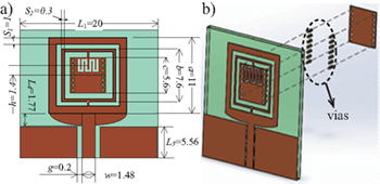
Fig. 1: Geometrical configuration of the triple-band antenna. (a) Front view of the proposed antenna. (b) Three-dimensional setup, where the upper square patch is electrically connected with the bottom one. L1 is the length of the substrate, and L2 denotes the width of the substrate. a is the length of the outermost strip, b represents the length of the inner ring, and c is the length of the square patch. L3 measures the width of the virtual ground, L4 is the height of the gradually varied impedance matching element, i.e., the transitional pair, g denotes the gap width between CPW and the virtual ground, and w is the feeding-strip width of CPW. The offset distance of the interdigital structure from the center of the square patch is denoted by h, while  ,
,  and
and  represent the finger width, the finger length and the gap width of the interdigital structure. The diameter of the via D is 0.4 mm. The thickness of the substrate H is 0.762 mm.
Download figure:
Standard imageTo build physically reasonable equivalent structural or circuit models for the proposed CSRR-loaded antenna, the surface current distributions at the first two resonant frequencies are explored. As shown in fig. 2(a), the surface current at 4 GHz is mainly distributed on two square strips and on the edges of the inner square patch, establishing a square CSRR structure. It reveals that this structure contributes to the first operating frequency band. Due to the symmetry of the antenna, the current is equally divided and flows to the right and the left halves of the structure. Thus we adopt the circuit model shown in fig. 2(b), where C1 and L1 denote the total capacitance and inductance of the square CSRR. Strictly speaking, however, there exist two main discrepancies between our structure and the classic CSRR proposed in [11] and [12]. One shows in shape, i.e., the former is square whereas the latter is circular. The other is the non-negligible additional current flow caused by the limited width of the outermost strip when estimating the total inductance. In practice, we transform the square CSRR into a circular one, which is illustrated as Structure 1 in fig. 2(c). We take

The average equivalent radius  and slot width
  are defined as

To calculate the inductance of our equivalent structure, we apply the superposition theorem. Suppose that the source current flows only into the inner ring strip, a quasi-CPW structure, composed of the patch, the inner strip and the fairly wider outer strip, contributes in part to the total inductance, which is shown in fig. 2(c). The other part is contributed by the outermost ring strip due to the current distribution on it as shown in fig. 2(a). By further ignoring the influence of the inner strip and the patch, we can get a simplified mono-strip. Therefore, we estimate the total inductance by considering LCPW (quasi-CPW structure) and LMON (mono-strip) connected in parallel. The mutual inductance between the inner and outermost rings is considered in LCPW.

Fig. 2: (a) Current distributions at the first resonant frequency, and (b) the equivalent circuit model of the antenna at the first resonant frequency. (c) Equivalent structures for estimating L1 and C1, respectively. (d) Current distributions at the first resonant frequency, and the normalized current densities along (e) the outermost strip and (f) the inner strip.
Download figure:
Standard imageFurthermore, we find that the finite-sized  and asymmetric
  ground in our quasi-CPW structure has little influence on the inductance value [16]. The LCPW can thus be estimated by the impedance ZCPW of coplanar waveguide [17], which reads

where vc denotes the speed of light in vacuum, K(k) represents a complete elliptic function of the first kind with  and
and  . Then, one can approximate the inductance of the monostrip by the following equation in [18,19], which reads

where  is the permeability, and
  . Therefore, the total inductance reads,

As for the capacitance, the C1 of Structure 1 in fig. 2(c) can be approximated by that of a metallic disk of radius  surrounded by a ring slot with the outer radius
  . An analytical prediction for the capacitance of Structure 2 reads [12]
with  , where Sn(x) and Jn(x) denoting the n-th–order Struve and Bessel functions, respectively. We then have
  .
.
Finally, one can apply the following expression:

to estimate the first resonating frequency of the antenna. The predicted f1 by eq. (7) is 4.27 GHz, quite comparable to the measurement (3.95 GHz) and the full wave simulation (4.10 GHz).
Similarly, one can characterize the operating mechanism at the second resonant frequency by observing the surface currents (as shown in fig. 2(d)). In detail, the normalized current densities of the outermost strip (trace  ) and the inner strip (trace
  ) are illustrated in figs. 2(e) and (f), respectively. Compared to currents around the first resonant frequency (blue solid line), the current distributions (red dashed line) at the second resonant frequency exhibit a higher mode.
Through comparing the number of current nodes (where the charge accumulates) or the equivalent wavelength of the currents, one can readily find the approximate ratio of the higher-mode resonance frequency to the fundamental one [20,21]. As shown in figs. 2(d) and (e), there exist two and three current nodes on the outer strip at f1 and f2, respectively. The relationship between the frequencies and the number of current nodes can then be written as,

with n1, n2 representing the numbers of current nodes at two different frequencies. Meanwhile, for the currents on the inner strip, the equivalent wavelengths around f1 and f2 can be estimated as

where  and
and  denote the length of trace
  and
and  , respectively. Note that discontinuities can be observed at the corners of the strips, e.g., point B and E, and should be excluded when considering the current nodes or equivalent wavelengths. Also note the non-uniform spacing of the nodes for the higher orders are due to the curvature of the CSRR [20]. In this case, one can practically estimate the second resonant frequency by

Thus, the estimated second resonant frequency equals 6.15 GHz, which is comparable to the measured (6.00 GHz) and simulated (5.74 GHz) results.
As for the third resonant frequency, the CRLH structures have little influence on the first two operating frequency bands, but contribute mainly to the third one as expected. This point can be witnessed in fig. 3, where the return loss of the proposed antenna is compared with that of the antenna without the CRLH structures. The illustrated independence of the resonances of FG-CSRR ensures that one can freely add extra circuit elements or topology into the inner patch, which would readily achieve multiband or multimode property as well as miniaturize the total size of the designed system. The characterized triple-band antenna is fabricated on a TP-450 substrate shown in fig. 4. The measured and simulated return loss coincide well as also shown in fig. 4.
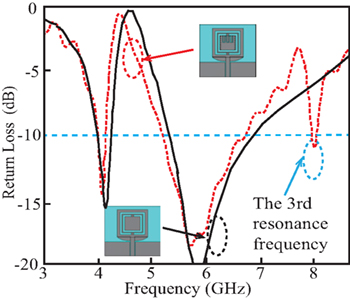
Fig. 3: The return loss comparison between the proposed antenna with inter-digital capacitor and vias (red dashed line), and the antenna without left-handed structures (black solid line).
Download figure:
Standard image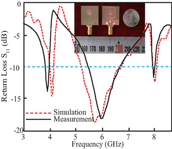
Fig. 4: The front and the bottom views of the fabricated antenna prototype and the measured and simulated return loss.
Download figure:
Standard imageTo further generalize the characterization method, the geometric parameters of the FG-CSRR-loaded antenna above should be scaled or altered to achieve a different operating frequency band. Since the CRLH structure contributes little to the concerned frequencies, one can reasonably omit it in the simulation for escalation. First, the antenna is scaled as a whole. After doing the same procedure as aforementioned, the estimated resonant frequencies (red and blue solid lines) are juxtaposed with the simulated ones (cross and circle scatters), as shown in fig. 5(a). When the permittivity of the dielectric substrate varies, the calculated and simulated frequencies are shown in fig. 5(b). Besides, one could also change some geometric parameters, e.g., the width of the inner or outermost strip (as shown in figs. 5(c) and (d)).
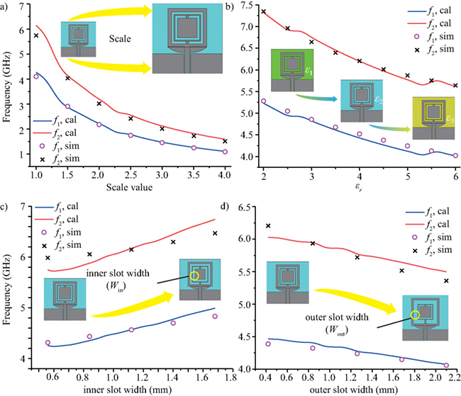
Fig. 5: The simulated and calculated resonant frequencies when (a) the antenna is scaled; (b) the permittivity of the substrate changes; (c) the width of the inner slot and (d) that of the outer slot are altered.
Download figure:
Standard imageThrough the simulations, it is interesting to notice that the ratio of the second resonant frequency to the first one maintain insensitive to the geometric parameters of the antenna. For the purpose of estimation, we can choose  , which means the higher mode at the second resonant frequency should be nearly
  -mode, just like the second mode of the SRR studied in [20]. Good consistency can be seen in fig. 5 between the calculated results and the simulations under all the posed alternations. Therefore, the proposed characterization of the FG-CSRR is well justified.
Looking back to the previous researches, we can also prove the efficiency of our proposed characterization. For instance, a compact size multiband microstrip antenna loaded with FG-CSRR is proposed in [15]. The rectangle-shape structure can be readily equivalent to a circular one by taking the average length of the corresponding sides. Under this transformation, when using our proposed estimation method, the calculated  and
and  (estimated as
  -mode) are quite comparable to the simulated 5.0 GHz and 8.7 GHz. Hence, this example also sufficiently validates our method.
In conclusion, we propose for the first time analytical models to predict the resonant frequencies of the FG-CSRR structure —maintaining high accuracy and greatly reducing the complexity of optimization by the full wave analysis. As a proof of concept, the operating frequencies of a triple-band antenna loaded with FG-CSRR is proposed and analyzed in detail. Moreover, the proposed method is qualified as an extremely robust approach by applying alternations in the geometric parameters. All the calculated results, simulations and measurements are well consistent, and validate the efficiency of our characterization approach. Compared with the previous work in CSRR characterization, we take the finiteness of the outermost ground into consideration and achieve it in an analytical way with explicit expressions. The second resonant frequency is also characterized readily. The proposed FG-CSRR-loaded antenna and its characterization would shed light on the future research. Firstly, the isolation between the FG-CSRR resonances and its inner patch guarantees the leverage of designing multiband, multimode and miniaturized microwave devices. Secondly, the analytical method can efficiently facilitate the design of such devices. Finally, relevant antenna synthesis in any frequency band could be inspired to explore both analytical and explicit approaches, e.g., lumped resonant circuit models.
Acknowledgments
This work was supported by the National Natural Science Foundation of China (NSFC) under the grants No. 61671178 and No. 61301013.