


Abstract
Convergence of ultrasonic energy is of great importance in the medical and engineering fields. In this work, ultrasonic focusing based on circular Airy-like beam (CALB) is numerically and experimentally demonstrated. The CALB focusing can be achieved simply using a planar resin ring lens immersed in water. At 2 MHz, the acoustic intensity at the focus can reach 257 times that for the incident wave. Arising from the self-healing feature of Airy beams, the CALB focusing can be well maintained even if there exists an obstacle in the acoustic path. Meanwhile, the focusing behaviour is well performed in a broad frequency range of 1.5 MHz to 3.1 MHz due to the simple and non-resonant design. By adjusting the frequency of the incident waves, the focal length can be modified without changing the lens structure. The CALB focusing and the corresponding planar lens may promote wide applications in ultrasound imaging, non-destructive testing, acoustic tweezing and medical diagnostic techniques.
Export citation and abstract BibTeX RIS
Introduction
Focusing ultrasonic waves, as one of the essential means of manipulating ultrasound, play an important role not only in ultrasound diagnosis and biomedical imaging in the medical field [1,2], but also in non-destructive detection techniques and underwater communication in the engineering field [3,4]. Numerous designs of lenses have been investigated to achieve acoustic focusing [5–15]. Conventional acoustic lenses are usually constructed from uniform materials with curved shapes for acoustic focusing. These lenses generally have either a cumbersome shape or a low efficiency due to the trade-off between the impedance mismatch and the material refractive index. Owing to the planar profile and easy fabrication, Fresnel zone plate (FZP) lenses are introduced to focus acoustic waves when the curved shape lenses are difficult to access [5–8]. However, the low efficiency of FZPs limits their practical applications [9]. The emergence of acoustic metasurfaces (AMs) has provided great power in acoustic focusing [10–15]. The AM lens can be fashioned into a compact planar profile of subwavelength thickness. However, they are usually frequency sensitive and mainly implemented for airborne sound because of their structural complexity. Moreover, acoustic focusing still suffers from some complicated environments such as the presence of obstacles in the propagating path.
In recent years, the optical circular Airy beam (CAB) has attracted great attention due to its unique abrupt autofocusing property [16–19]. The CAB can abruptly focus its energy in the focal region while keeping a low intensity profile before. With the advantage of autofocusing property, the CABs have found applications in biomedical treatment, microengineering, and particle manipulation [20–23]. Another unusual property of Airy beams is self-healing, which has been demonstrated both theoretically and experimentally [24,25]. The beams can self-reconstruct during propagation in the presence of a disturbance, which is very useful in practical situations. For example, in ultrasound diagnosis, the acoustic path is usually blockaded by the ribs or other organs between the target and the ultrasonic source. The properties of CABs mentioned above will also be of great interest in the acoustic community. In general, acoustic Airy beams can be generated by using the phase modulation method [26–29]. For instance, Gao et al. [28] proposed a zero-index medium lens with a desired phase profile to generate Airy-like beams. Our group showed that Airy-like beams could be realized by AMs composed of space-coiling structures [29]. However, due to the strong scattering effect and structural complexity in liquids, these designs cannot work well in water environments, which impairs their further practical applications.
In this paper, we demonstrate the experimental realization of an abruptly autofocusing circular Airy-like beam (CALB) in water. A concentric resin ring lens that matches the phase profile of the CAB is proposed to generate CALB focusing with a simple design. The focusing and self-healing characteristics of CALB are studied both numerically and experimentally. Meanwhile, the broadband property of the lens is illustrated in detail based on the finite-element method (FEM).
Theory and model
We study the CAB by considering its exponentially decaying version, and the field at the input plane can be expressed as [16,17]

where  is the Airy function with r0 representing the initial radius of the main Airy ring and w corresponding to the scaling factor,
  is the radial distance, and a > 0 is an exponential decay factor. The field distribution of the source function
  is shown in fig. 1 for
  ,
,  , and
, and  .
.  is the working wavelength of the ultrasonic wave in water, corresponding to the work frequency of 2 MHz. The radius of the highest intensity Airy ring is
  , and its full width at half maximum (FWHM) is approximately 2.28w. To illustrate the circular Airy beam more clearly, we plot the field (black dashed line for left-hand scale) and phase profile (red solid line for right-hand scale) of the function ϕ along the x-axis in fig. 2(a). We note that ϕ oscillates around zero with decreasing amplitude for x > r0, and exhibits exponentially decaying nature for x < r0. The phase distribution shows alternating segments with constants of 0 and π for x > r0.
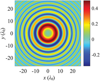
Fig. 1: Field distribution of the source function ϕ at the input plane with  ,
,  , and
, and  .
.
Download figure:
Standard image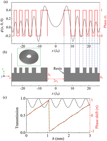
Fig. 2: (a) Field (black dashed line for left-hand scale) and phase profiles (red solid line for right-hand scale) of the source function ϕ along the x-axis. (b) Geometry of the resin ring lens along the x-axis for the generation of CALB. The inset shows the schematic of the three-dimensional lens. (c) Transmission coefficient (black dashed line for left-hand scale) and phase shifts (red solid line for the left-hand scale) of the resin plate as a function of thickness h. The green dashed line represents the phase shift calculated using eq. (2).
Download figure:
Standard imageIt is found that the effects of Airy beams mainly arise from the modulation of the spatial phase distribution, and the amplitude variation is not very important [27–29]. Thus, a concentric circular resin ring lens is designed by preserving the phase distribution of CAB but ignoring the amplitude variation for the generation of CALB. The resin ring lens is composed of ten concentric resin rings and its geometry along the x-axis is shown in fig. 2(b). The alternating phase segments determine the length of the pattern in the transverse direction (blue dashed lines), i.e., the varying widths of the ten resin rings, as shown in fig. 2(b). The inset shows the schematic of the three-dimensional lens. The thicknesses of the high and low resin rings are h0 and h1, respectively. The required phase modulation ( phase shift between the adjacent rings) is achieved by adjusting the thickness h1 when h0 is fixed.
For a normally incident plane wave, it experiences a phase shift when the plane wave passes through the resin plate. The acoustic phase shift of the resin plate with thickness h can be expressed as [30]

where  is the wavelength in the background fluid and n represents the refractive index of the longitudinal waves in the resin. Figure 2(c) shows the transmission coefficient and phase shift of the resin plate as a function of thickness h. The frequency of the incident plane waves is set to 2 MHz. Field simulations are performed based on the finite-element method (using the commercial COMSOL Multiphysics software with the acoustic-solid interaction module). Pressure acoustics and solid mechanics modules are used to describe the water and resin, respectively. Perfect matched layers (PMLs) are used in the upper and lower planes to model the open boundary condition. Periodic boundary conditions are imposed on the left and right sides of the resin plate. The resin plate is immersed in water with a density of 998 kg/m3 and a speed of sound of 1482 m/s. The mass density, Young's modulus, and Poisson ratio of the resin are 1160 kg/m3, 2.51 GPa, and 0.41, respectively. As evident from fig. 2(c), the phase shift varies linearly with the thickness of the resin plate. The result calculated using eq. (2) is also plotted as a green dashed line for comparison. The simulated result matches very well with the theoretical result. Meanwhile, the transmission coefficients are higher than 0.75 over the entire thickness range, indicating the highly efficient transmission of the resin plate. According to the phase requirement of the CAB field in fig. 2(a), the phase shift of π between the adjacent rings can be achieved with
  when the thickness h0 is fixed at 3 mm. Therefore, the geometry of the resin ring lens for the CALB is designed simply with a highly efficient transmission.
Ultrasonic CALB focusing
We now demonstrate the generation of underwater CALB focusing using the proposed resin ring lens. Simulations are performed with a two-dimensional axisymmetric model in cylindrical coordinates to reduce the computational cost. The PMLs enclose the entire computational domain to eliminate the boundary-reflected acoustic waves. The largest mesh element size is less than one-eighth of the incident wavelength, and further refined meshes are applied in the domain of the resin rings. The incident excitation is a time-harmonic plane wave, and the amplitude of the incident pressure p0 is fixed at 1 Pa. The frequency of the incident plane waves is 2 MHz, and the background fluid is water. Figure 3(a) shows the side view of the acoustic intensity distribution of a plane wave passing through the resin ring lens placed on the xy plane. The yellow arrows indicate the direction of the incident plane wave. The acoustic plane wave propagates from the bottom into the lens, and then a CALB is exported from the up surface of the lens. It is clear that the beam autofocuses after a certain propagation distance. The focal spot (the maximum intensity) is located at  . A snapshot of the transverse pattern at the focal plane is displayed in the inset of fig. 3(a). Although the resin-ring lens has a number of outer rings, the bright ring contains almost half of the total energy and moves on a parabolic trajectory. Its spatial pattern and propagation trajectory are similar to those of CABs in previous reports [17–19]. Using the prediction of the one-dimensional Airy beams [27–29], the radius R(z) of the primary Airy ring is described by

where z is the propagation distance. The radius  is the maximum when
  and decreases with increasing z, which is shown as a parabolic line. The green dashed lines in fig. 3(a) indicate theoretical propagation trajectories of the main lobes, which match well with the simulated results. When
  , z is approximately equal to the focal length
  , which is defined as the length of the projection of the maximum intensity on the CAB axis. By using eq. (3), we can estimate the focal length of the autofocusing CAB as

It is obvious that the focal length of the CAB directly depends on r0, w, and  . In our case (
 ,
,  and
and  ), the focal length of the CALB calculated using eq. (4) is approximately
  , which is in good agreement with the simulated result of
  .
.
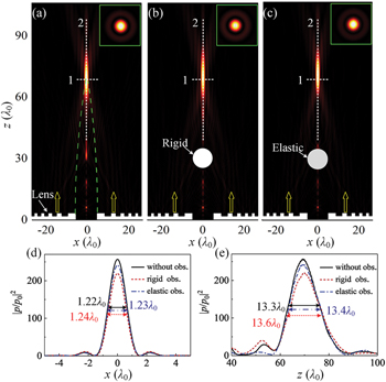
Fig. 3: Side views of acoustic intensity distributions of CALBs (a) without an obstacle, (b) with a rigid obstacle, and (c) with an elastic obstacle in the acoustic path. The arrows indicate the direction of the incident plane wave. Intensity contrasts  along the dashed (d) line "1" and (e) line "2". Insets of (a), (b) and (c): snapshots of the transverse pattern at the focal planes.
Download figure:
Standard imageAs the Airy beams can be self-reconstructed during propagation when obstacles exist, it is expectable that the CALB focusing with a self-healing characteristic would be achieved. To study the self-healing property of the CALB, two types of solid spherical obstacles are considered in the simulations. One is a rigid sphere, and the other is a solid elastic sphere. The obstacle with a radius of  is placed at the location of (0, 0,
  ). The side views of the acoustic intensity distributions of the plane wave through the resin ring lens with a rigid obstacle (white circle) and an elastic obstacle (gray circle) are shown in figs. 3(b) and (c). The spherical obstacle can just block the main lobes of the CALB. The wall of the rigid obstacle is taken as a sound-hard boundary in the simulation because of the large impedance mismatch between the rigid obstacle and water. In the case of the elastic obstacle, the solid mechanics module is used to describe the solid elastic material. The mass density, Young's modulus, and Poisson ratio of the elastic obstacle composed of polystyrene are 1050 kg/m3, 3.372 GPa, and 0.33, respectively. In fig. 3(b), the CALB is scattered by the obstacle but recovered after passing the solid obstacle, and then abruptly autofocuses. The focus (peak intensity) is also located at
  . A similar situation occurs when the CALB propagates though the elastic obstacle, as shown in fig. 3(c). The snapshots of the transverse pattern at the focal plane are displayed in the insets of figs. 3(b) and (c). To better view the performance of the CALB focusing, the intensity contrasts
  along the dashed lines "1" and "2" are plotted in figs. 3(d) and (e). The black solid, red dashed, and blue dot-dashed lines represent the intensity profiles without an obstacle, with a rigid obstacle, and with an elastic obstacle, respectively. p and p0 are the transmitted and incident pressures, respectively. The spatial resolution and depth of the focusing are measured by computing the FWHM and the full length at half maximum (FLHM), which are approximately
  and
and  , respectively. Benefitting both from the high transmission of the lens, the
  of the focus can reach 257, which is markedly high in acoustic lenses [13–15]. With a rigid or an elastic obstacle, the FLHM, FWHM and focal length remain almost unchanged except that the intensity of the peak decreases slightly. These results indicate that the proposed lens still exhibits good focusing performance even if a large obstacle partially blocks the acoustic path.
Additionally, the proposed resin ring lens can work well in a broad frequency region due to the simple and non-resonant design, although the lens is designed at a fixed frequency. Figures 4(a), (b), and (c) show the side view of acoustic intensity distributions at frequencies of 1.5 MHz, 2 MHz, and 2.5 MHz, respectively. In these simulations, the structure of the lens is fixed, i.e., the parameters r0, w, a, and  of the CALB remain unchanged. At these frequencies, the resin ring lens can still realize good focusing, and the focus shifts with the frequency. The intensity contrasts
  along the dashed lines "1" and "2" are plotted in figs. 4(d) and (e). The red dashed, black solid, and blue dash-dotted lines represent the intensity profiles at frequencies of 1.5 MHz, 2 MHz, and 2.5 MHz, respectively. The maximum intensity contrasts are approximately 212, 257 and 275, and the corresponding focal lengths are
  ,
,  , and
, and  . To further study the frequency response properties of the resin ring lens, the intensity contrast
  at the focus (red circle line for right-hand scale) is plotted as a function of frequency in fig. 4(f). Good focusing performance can be maintained over a broad frequency range. The focal length (black squares for the left-hand scale) is also plotted as a function of frequency in fig. 4(f). Increasing the frequency from 1.5 MHz to 3.1 MHz, the focal length increases almost linearly from
  to
to  . These results are in accordance with eq. (4), where the focal length is inversely proportional (proportional) to the wavelength (frequency). Thus, we can manipulate the focal length of the resin ring lens by simply changing the frequency of the incident wave without changing the lens structure.
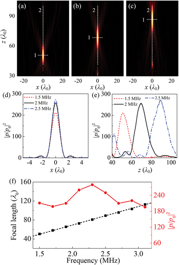
Fig. 4: Side views of acoustic intensity distributions of the CALB focusing at frequencies of (a) 1.5 MHz, (b) 2 MHz, and (c) 2.5 MHz. Intensity contrasts  along dashed (d) line "1" and (e) line "2". (f) Focal length (black squares for left-hand scale) and intensity contrast
  at the focus (red circle line for right-hand scale) of the CALB focusing as a function of frequency. The black dashed line is plotted for a better view.
Download figure:
Standard imageExperimental verification
The acoustic fields of the CALB focusing can be visualized using the Schlieren imaging method [31], which is based on phase modulation of the light produced via the acousto-optic effect. A planar wave field is generated by using an ultrasonic transducer (DYG-2M, Dayu Electric, China) with a diameter of  and a center frequency of 2 MHz. The acoustic field is generated in a transparent rectangular water tank made from quartz glass with dimensions of 10×12×12 cm3 (width × length × height). An intensified charge-coupled device (iCCD) camera (iStar DH734-18U-03, Andor, UK) is placed at the imaging plane to record the images. The resin ring lens with a diameter of
  is obtained by the three-dimensional printing prototype, as shown in the inset of fig. 5(a). The lens is bonded to the ultrasonic transducer using a coupling material and then immersed in water.
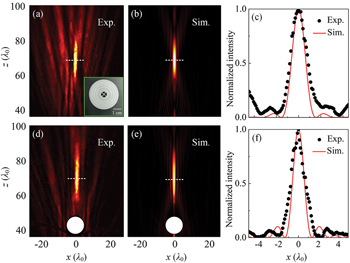
Fig. 5: (a) Measured and (b) simulated acoustic intensity distributions of the CALB focusing. (c) Normalized intensity profiles along the dashed lines in (a) and (b). (d) Measured and (e) simulated acoustic intensity distributions of the CALB focusing with an obstacle in the acoustic path. (f) Normalized intensity profiles along the dashed lines in (d) and (e). Inset of (a): photograph of the resin ring lens sample.
Download figure:
Standard imageFigure 5(a) shows the Schlieren image of the acoustic intensity distribution of the CALB focusing. The corresponding simulated acoustic intensity field is shown in fig. 5(b) for comparison. The experimental acoustic intensity field is in good agreement with the simulated result. The small discrepancies may arise from the background light field, the photocurrent in the iCCD, and the out-of-level condition of the resin ring lens. To demonstrate this focus more clearly, the intensity profiles along the dashed lines in figs. 5(a) and (b) are plotted in fig. 5(c). The black circles and red solid line represent the measured and simulated results, respectively. The acoustic intensities are normalized by the maximum value. It is obvious that the proposed resin ring lens exhibits good performance of converging acoustic waves. Figure 5(d) shows the Schlieren image of the acoustic intensity distribution of the CALB focusing with an obstacle. A metal ball with a radius of  is fixed at the location of (0, 0,
  ), as shown in fig. 5(d). Sharp focusing can be maintained due to the self-healing feature of the CALB. The corresponding simulated acoustic intensity field is shown in fig. 5(e) for comparison. Good agreement between the experiment and simulation is obtained. The intensity profiles along the dashed lines in figs. 5(d) and (e) are plotted in fig. 5(f), where the black circles and red solid line represent the measured and simulated results. It is clearly observed that the measured results match well with the simulated results. Comparing the results in figs. 5(a) and (c), the FWHM and the intensity peak of the CALB focusing remain nearly unchanged. We can therefore conclude that even if there exists an obstacle in the acoustic path, the proposed lens with the self-healing feature still exhibits a good focusing performance.
Conclusion
We presented a generation of underwater CALB focusing by modulating the transmitted phase of an array of resin rings. According to the phase distribution of CAB, the width and thickness of each resin ring could be determined. At 2 MHz, the intensity contrast  can reach 257 times at the focus, while the FWHM and FLHM for the CALB focusing were
  and
and  , respectively. The CALB focusing was well maintained even if there existed an obstacle in the acoustic path. We further found that the proposed resin ring lens could operate in a broadband manner with good focusing performance. By increasing the frequency from 1.5 MHz to 3.1 MHz, the focal length increased almost linearly from
  to
to  . Finally, the focusing and self-healing characteristics of CALB were confirmed experimentally using the Schlieren imaging method. Given the design efficiency and simplicity, our work may have potential applications in biomedical ultrasonics, underwater detection, and acoustic micromanipulation technology.
Acknowledgments
The authors thank Zheng Xu from Tongji University for the experimental assistance. This work was supported by the National Natural Science Foundation of China (grants Nos. 12174197, 11874222, 12027808, and 12074191).
Data availability statement: All data that support the findings of this study are included within the article (and any supplementary files).