

Abstract
We theoretically study the frictional damping of a small probe object on a coated planar surface, analyzing the resulting phonon modes via a theory of viscoelasticity. Three different types of excitations are found to contribute to friction in distinct ways: traveling (3D) spherical waves, traveling (2D) surface waves, and evanescent waves. While traveling waves transport energy away from the probe, determined by long range elastic properties (wavelength), evanescent waves transform energy into heat in a near-field range, characterized by the size of the probe. Thus, fundamentally different behaviors are predicted, depending on coating thickness and material properties.
Export citation and abstract BibTeX RIS

Published by the EPLA under the terms of the Creative Commons Attribution 4.0 International License (CC-BY). Further distribution of this work must maintain attribution to the author(s) and the published article's title, journal citation, and DOI.
Sliding friction is a complex phenomenon, involving surface mechanics [1–8] and production of heat in the surrounding media. In the latter process, the relevant degrees of freedom have been found to include electronic [9–13] and phononic ones [8,11–23]. The role of phonon modes can be isolated by tuning them while keeping the surface properties and contact mechanics unchanged. This has been achieved by inducing a phase transition in the solid [13,19], or by changing an external electric field [20].
Studying friction on layers of different thickness is another way of achieving this goal; it is especially insightful as it not only allows material properties to be tailored while limiting changes in the contact surface, it also reveals how deep friction feels into the material. Many numerical and nanoscale experimental studies have been done on the effect of layers [24–36], with a variety of interesting behaviors. For example, while adding graphene layers between sliding bodies can substantially reduce friction [33], both increases [24–26] and decreases [27,30–32] in friction have been observed as the number of graphene layers is increased. Friction has also been observed to decrease with thickness for other layered materials, such as molybdenum disulfide and niobium diselenide, when they are weakly anchored to the substrate [32]. A numerical study, in contrast, found that friction increases with thickness, when the bottom layer absorbs incoming phonons [34]. Additionally, it has been reported that friction is smaller for strongly anchored samples compared to weakly anchored ones, suggesting that the changes in friction could be results of changes in local deformations [28,29,36]. The complexity of the observed behavior calls for a theoretical analysis that systematically addresses the dependence of phononic damping on layer thickness, boundary conditions, and material properties.
In this manuscript, we analyze friction of a nanoscopic object on a 3D planar coated substrate, treating phonon modes via a field theory of viscoelasticity that includes phonon attenuation. We find that friction arises due to traveling spherical waves, cylindrical surface waves, or evanescent waves, each dominating in different regimes of material properties and coating thickness. A finite viscosity thus not only results in phonon attenuation, but also, here more importantly, in losses from evanescent waves. Consequently, friction shows drastically different dependencies on coating thickness ranging from short range to long range behavior, and can increase or decrease with coating thickness. These regimes are determined by the phonon attenuation coefficients and the refractive index.
Consider a probe coupled to an isotropic solid filling the space  (see fig. 1). The probe oscillates parallel to the surface, so that its x coordinate is
  . The coupling with the surface causes a force acting on the probe, whose x-coordinate is
  . The damping coefficient or friction coefficient of the probe Γ is defined as
  [37]
[37]
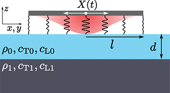
Fig. 1: Investigated system: a probe is coupled to the surface of a coated substrate, and oscillates parallel to it. The coupling interaction carries an interaction radius l. The coating of thickness d and the substrate are characterized by mass density ρ and transverse  and longitudinal
  speeds of sound, as indicated.
Download figure:
Standard imageThe specific form of coupling is not important for the conclusions of this manuscript, as detailed in the Supplementary Material Supplementarymaterial.pdf (SM). We thus use a simple linear one, which allows us to find analytic expressions,

where  marks a position on the surface, and
  is the x-component of the phonon field at z = 0 (introduced below).
  is the particle number per unit area [38], and κ is the coupling strength. Equation (1) contains a Gaussian envelope of width l, introducing a length scale of the interaction range or probe size.
The first term in eq. (1) is the force in absence of phonon excitations; it is in phase with X(t) and does not contribute to the damping coefficient Γ. The second term is the force due to excitations of the phonon field  , treated via a theory of viscoelasticity, i.e., using a Kelvin-Voigt model [39–42],

The coupling to the probe enters eq. (2) via a time-dependent boundary condition. The resulting solution for ux contains a part that is phase shifted with respect to X(t), yielding the damping coefficient Γ [16,17]. The oscillating probe excites phonons, whereby its motion is damped. The solution of this problem proceeds via the Green's function of eq. (2) (SM).
Equation (2) is a widely applicable model of phonon dynamics [39–41], and related models have been influential in understanding friction [16,18]. It contains two fundamental modes with longitudinal,  , and transverse,
  , speeds of sound. K and μ (ξ and η) are the bulk and shear elastic (viscous) moduli, respectively, and ρ the mass density.
  and
and  are complex due to finite viscous moduli, i.e., eq. (2) contains phonon attenuation. Microscopically, such attenuation may be caused by phonon-phonon, phonon-electron, or phonon-defect scattering. For simplicity, we assume
  , independent of ω, a good approximation for solids [16,43–45].
  thus drops out of the discussion.
The bulk situation, where the coating thickness d in fig. 1 is infinite, was extensively studied previously [16,17,42,46]. In this case, the probe excites spherical waves  (SM), and the damping coefficient reads

with  ,
,  , and
, and  the real part of
  . Equation (3) is valid for
  , with phonon wavelength
  . For typical speeds of sound and l in the nanometer range, the corrections to eq. (3) are small for
  . This number,
  , is large compared to typical frequencies excited by the probe, since they are expected to be in the range
  [11,14,15,19,20,30–32]. Additionally, eq. (3) assumes the quality factor
  , the ratio between phonon decay length and phonon wave length, to be large compared to unity. This seems a justified assumption as well, as seen in estimates of the order of
  [47,48] (see table 1 for experimental parameters). Despite Q being large, phonon attenuation is essential for friction since, as shown below, it dominates the behavior in certain regimes.
Table 1:. Parameters typical for AFM experiments on solids: radius of contact l, frequency ω, mass density ρ, and shear elastic modulus μ.
| la |

|

|

|
|---|---|---|---|

|

|

|

|
| a References [19,27,32]. | |||
| b References [19,20,30–32]. | |||
| c Reference [53]. | |||
The two leading terms in eq. (3) have fundamentally different physical origins. The first, called the elastic contribution, corresponds to transport of energy by traveling waves, and it persists without phonon attenuation [16,42]. The second, called the viscous contribution, is proportional to viscosity  . We discuss its physical origin below. Their relative weight is the dimensionless viscosity,

which depends on material properties and probe size l. The numbers of table 1 for typical AFM conditions imply  . We thus first discuss the case of
  , where the bulk case of eq. (3) is dominated by the viscous contribution (using
  )
)

For finite values of d, we note that the boundary condition at the interface between coating (labeled with the subscript 0) and substrate (subscript 1) is determined by the refractive index  and
and  [49]. It is insightful to start with the limit n = 0 (see footnote
1
), which yields a Dirichlet boundary condition (DBC) of
[49]. It is insightful to start with the limit n = 0 (see footnote
1
), which yields a Dirichlet boundary condition (DBC) of  [40,49]. In this case the substrate is much stiffer than the coating, and phonons are totally reflected at the interface, with phase shift π.
Figure 2(a) shows Γ as a function of d for n = 0 and  , growing linearly in d, and saturating to the bulk value of eq. (5) for large d, with a cross-over length scale around
  . Indeed, we find that, for small d, the leading order of Γ is linear in d,

Γ vanishes as  , because the coating, when placed on a stiff substrate, supports fewer phonons as
  . In the second step in eq. (6), we used eq. (5) to replace
  , making the mentioned saturation to
  at
at  apparent. The dependence of Γ on d is short range, set by probe size l of eq. (1).

Fig. 2: Damping coefficient Γ for (a) n = 0 and (b) n → ∞ as a function of (scaled) distance d, in the viscous limit  . The solid line shows numerical evaluation, dashed lines give the asymptotes of eqs. (5), (6) and (7), respectively. Sketches give the fundamental wave solutions in the corresponding regimes.
Download figure:
Standard imageHow is this short range decay possible over distances much smaller than the wavelength? The motion of the probe excites not only (attenuated) traveling waves, but also evanescent waves that decay within a range of l. In the presence of finite viscosity, they contribute to energy absorption, and thus to the damping coefficient Γ. In fig. 2, this mechanism outweighs the energy transported by traveling waves, which is why eqs. (5) and (6) carry  as a factor.
The opposite limit of boundary conditions, n → ∞, corresponds to a freestanding coating or a much more compliant substrate, and the waves obey a Neumann BC (NBC),  with stress tensor
  and surface normal
  [49]. Phonons are totally reflected without phase shift. This renders Γ fundamentally different from the case of n = 0 as shown in fig. 2(b); Γ diverges for small d and converges to the bulk value on a scale of
  . Expanding this case for small d yields

In this case, the probe excites traveling surface waves,  , i.e., the coating oscillates like a freestanding 2D sheet. Energy is transported along the surface, rather than absorbed; eq. (7) is independent of viscosity
  . As the sheet gets more compliant with
  , amplitudes of excitations get larger, and formally diverge as
  . The second equality of eq. (7) implies the mentioned saturation length of
  . With l on the scale of nanometers, this length is of the order of microns. It will be interesting to compare these surface modes to so-called puckering [32,36] or ploughing [28,35] identified in previous work.
The cases of n = 0 and n → ∞ provide a reference for the discussion of an arbitrary refractive index n. For simplicity, we assume that the quality factors of the coating and substrate are identical, making  real, and use
  (see footnote
2
). For finite values of n, we note a numerical challenge in evaluating the longitudinal modes, so that we restrict the shown data to transverse waves (SM).
(see footnote
2
). For finite values of n, we note a numerical challenge in evaluating the longitudinal modes, so that we restrict the shown data to transverse waves (SM).
Figure 3 shows Γ as a function of d for various n, at  and
and  ; Γ is monotonic in d, and stays within the bounds of the limiting cases of n = 0 and n → ∞. Importantly, for a thin coating,
  , Γ approaches the bulk value of the substrate, indicated as bars on the y-axis. These are obtained by eq. (3) with the material parameters of the substrate
3
,
4
. Γ thus varies between the bulk results of the substrate
, Γ approaches the bulk value of the substrate, indicated as bars on the y-axis. These are obtained by eq. (3) with the material parameters of the substrate
3
,
4
. Γ thus varies between the bulk results of the substrate  and of the coating
  .
.
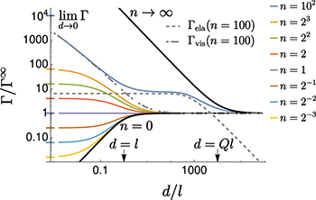
Fig. 3: Damping coefficient Γ for various refractive indices n, using  and
and  , only considering transverse waves. Marks on the y-axis are (analytic) values of
  for the corresponding n. The gray dashed lines are the purely elastic and viscous contributions at n = 100.
Download figure:
Standard imageThe curves of fig. 3 up to  can be understood by these two limiting cases, and a transition on the length scale l. These cases are thus dominated by evanescent waves. The dimensionless viscosity of the substrate equals
  , and goes down for large values of n. The damping coefficient of the bulk substrate, i.e., the behavior at small d, is thus dominated by traveling waves at large n. Indeed, for n → ∞, the behavior of fig. 2(b) is approached. For intermediate values of n (
 in the graph), a two-step decay occurs, with evanescent waves for
  and
and  , and traveling surface waves for
  .
.
What about the case of  where the limit d → ∞ is dominated by traveling waves? Despite less experimental relevance to AFM experiments, we include this insightful case in fig. 4 for completeness, focusing on n = 0 (see SM for n → ∞). As seen in the figure, for
  the curves are similar to fig. 2(a). This is because, for n = 0, the coating does not support traveling waves for d ≲ λ (SM). For d ≳ λ, traveling waves are excited, yielding a sharp transition between evanescent and traveling waves at
  , followed by peaks. These are due to interference effects between outgoing and reflected traveling waves (SM). For d ≫ λ, the bulk value of eq. (3) is approached.
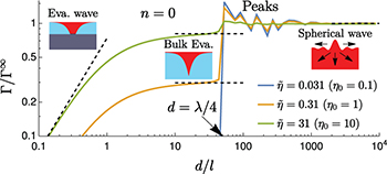
Fig. 4: Damping coefficient Γ as a function of (scaled) distance for n = 0, for three values of  . The black dashed lines represent the asymptotes of eqs. (3), (5) and (6). For the chosen parameters, the first peak is at
  .
.
Download figure:
Standard imageThis discussion allows identification of mechanism regimes, depicted in fig. 5. The limit of d → ∞ is dominated by evanescent waves for  , and by traveling waves for
  . This is indicated in fig. 5 by using different colors in the inset graphs. The line
  separates the same for
  , i.e., curves that begin with blue or red. This limit can be found from
5
, i.e., curves that begin with blue or red. This limit can be found from
5

Another separator is n = 1, dividing curves where  is larger than the limit of
  from the opposite. The last curve,
 ![$n=\sqrt[3]{\tilde\eta}$](https://content.cld.iop.org/journals/0295-5075/142/4/46001/revision3/epl23100128ieqn90.gif) , together with
, together with  , bounds two regimes with multiple transitions between traveling and evanescent waves. The latter occur because of the different d-dependence of traveling and evanescent waves.
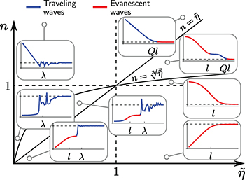
Fig. 5: Friction map. Depending on  and n, Γ is dominated by evanescent modes (red) and decays to bulk on a scale
  , or by traveling waves (blue), which decay on scales of Ql or λ. The lines separating the regimes are deduced from eq. (8). Gray dashed lines show the limit d → ∞ of eq. (3).
Download figure:
Standard imageThis framework identifies the main phononic mechanisms for damping between a probe and a coated planar surface, with vastly different behaviors. These regimes are expected to occur in experiments and simulations, whenever the thickness of coatings can be changed without changing contact mechanics. Figure 5 illustrates that pronounced dependence on layer thickness is expected, e.g., if the two materials show a refractive index very different from unity. The discussed isolated frequencies apply in non-contact measurements, where narrow frequency bands are excited [11,13–15]. In sliding experiments, one expects a spectrum of frequencies, so that the results reported here need to be averaged accordingly. It is important to note that the contributions by evanescent waves are frequency independent within the range given below eq. (3), making this average trivial. Friction from traveling waves has frequency-dependent features, see eq. (7), manifested as the peaks in fig. 4.
The presented model is simple and provides analytical results, which we expect to improve understanding of friction phenomena. The quantitative translation to the case of sliding motion needs to be investigated in future work [50]. We note however qualitative agreement with studies on graphene. Experiments [32] and simulations [27] reported friction on freely standing graphene flakes, i.e.,  , finding a decrease with increasing number of layers. The same trend is observed for mounted graphene layers (or flakes) [27,30–32]; graphene is much stiffer (
 [45,51,52]) than metal substrates (
 [53,54]), so that the case of
  applies too. Previous work attributed this behavior to the enhanced rigidity for thicker samples [27,32], leading to the suppression of surface waves, in agreement with our findings.
The framework of eq. (2) naturally includes Hertzian contact theory [40,55] in the limit of small frequencies. It is interesting to remark that the identified evanescent waves can equally be found from the slowly moving distortion field of contact theory. Moving this distortion field dissipates energy due to viscosity (SM). This way, this approach can be linked to a variety of other approaches based on contact theory [4,7,18,50] and local deformations [28,29,36]. Natural extensions include nonlinear systems, where, e.g., deeper indentations [28,29,36] can be studied. Lateral confinement was also found to be of importance [8], and it provides an interesting additional possibility to identify involved phonon modes. This can be address in the presented framework in future work.
Acknowledgments
This work was funded by the Deutsche Forschungsgemeimschaft (DFG, German Research Foundation), grant No. 217133147 via SFB 1073 (Project A01). We thank Richard L. C. Vink for stimulating discussions. In memory of Philip Rauch.
Data availability statement: All data that support the findings of this study are included within the article (and any Supplementary files).
Footnotes
- 1
For n = 0,
 is irrelevant.
 - 2
These two assumptions can be relaxed without additional challenge, yielding similar conclusions as the ones presented.
- 3
We assume that the surface coupling (here κ, nA and l) are the same for coating and for pure substrate.
- 4
In experiments, the limit
(thin coating) is expected to be different from d = 0 (no coating), because of different surface interactions for substrate and coating. - 5
See the SM for more discussion and the general case where n is complex and
.


