

Abstract
Edge localised mode (ELM) control may be essential to develop ITER scenarios with a reasonable lifetime of divertor components, whilst ELM pacing may be essential to develop stationary ITER scenarios with a tungsten divertor. Resonant magnetic perturbations (RMPs) have mitigated ELMs in high collisionality plasmas in JET. The efficacy of RMPs in mitigating the ELMs is found to depend on plasma shaping, with the change in magnetic boundary achieved when non-axisymmetric fields are applied facilitating access to small ELM regimes. The understanding of ELM pacing by vertical kicks or pellets has also been improved in a range of pedestal conditions in JET ( –1.3 keV) encompassing the ITER-expected domain (
 –2.4, H98(y, 2) = 0.8–1.2,
  ). ELM triggering is reliable provided the perturbation is above a threshold which depends on pedestal parameters. ELM triggering is achieved even in the first 10% of the natural ELM cycle suggesting no inherent maximum frequency. At high normalised pressure, the peeling-ballooning modes are stabilised as predicted by ELITE, necessitating a larger perturbation from either kicks or pellets in order to trigger ELMs. Both kicks and pellets have been used to pace ELMs for tungsten flushing. This has allowed stationary plasma conditions with low gas injection in plasmas where the natural ELM frequency is such that it would normally preclude stationary conditions.
Export citation and abstract BibTeX RIS
Corrections were made to this article on 13 May 2016. The publication year was corrected.
1. Introduction and background
Edge localised modes (ELMs) occur at the periphery of tokamak plasmas which operate in a high-confinement regime [1]. In this regime of improved confinement, a transport barrier, or 'pedestal', forms at the plasma edge, resulting in a strong localised pressure gradient. However, the large gradient in the pressure and the high current density which occur in the pedestal region can drive peeling-ballooning instabilities [2, 3], which are believed to be manifest as ELMs [1]. An empirical scaling of the energy released by ELMs suggests that the heat loads incident on the plasma facing components in ITER could cause intolerable damage unless mitigated [4]. In order to ensure an appropriate lifetime of plasma facing components in ITER, it is anticipated that at full plasma current robust ELM control will be required, either suppressing the ELMs completely or, at least, reducing the heat flux per ELM which is incident on the divertor plates [5]. Furthermore, operation with metal walls is complicated by the influx of high-Z impurities into the plasma causing high bulk radiation, which, if unmitigated, can result in radiative collapse and disruptions. ELM pacing has been used as an actuator for avoiding the build up of impurities in the plasma core. Therefore, ELM control can come in various forms: (i) ELM suppression, which completely avoids the occurrence of large Type-I ELMs and, it is anticipated, simultaneously increases pedestal transport to flush the impurities; (ii) ELM mitigation, which increases the ELM frequency and flushes the impurities whilst at the same time reduces the peak heat flux incident on the divertor plates; and (iii) ELM pacing, whereby the ELM frequency is increased, but the peak heat flux on the divertor is not reduced, typically because the wetted area on which the ELM power load is deposited, decreases. There are a number of actuators to achieve these control requirements, though the three envisaged for ITER (and those considered in this paper) are the application of resonant magnetic perturbations (RMPs), which perturb the magnetic field in the pedestal region, which is hypothesised to locally degrade the confinement; high frequency pellet injection, which triggers ELMs due to the three-dimensional density perturbation; and vertical plasma displacements—or 'vertical kicks'—which it is postulated alter the edge plasma conditions and stimulate peeling-ballooning instabilities. ELM suppression has only been achieved by means of RMPs in DIII-D [6, 7] and KSTAR [8]. ELM mitigation—that is to say an increase in the ELM frequency and reduction of the divertor heat loads—has been achieved with RMPs in ASDEX Upgrade [9–11], MAST [12–15] and JET [16, 17] and with pellets in DIII-D [18]. ELM pacing has been achieved by all actuators, for instance RMPs in NSTX [19], pellets in ASDEX Upgrade [20] and JET [21, 22], or vertical kicks in TCV [23], ASDEX Upgrade [24] and JET [25, 26]. More details on ELM control and the actuators planned for ITER can be found in [27].
This paper examines recent progress from JET in understanding how ELM control actuators affect the ELM behaviour as well as giving some examples of how this improved understanding has been utilised to control ELMs for plasma scenario development. Section 2 considers the effect that applying non-axisymmetric fields has on the plasma configuration and how this affects plasma edge stability, comparing the empirical observation of changes in ELM behaviour with 3d stability modelling. The mechanism whereby vertical kicks trigger ELMs is discussed in section 3. In section 4 the efficacy of pellets in triggering ELMs at different times in the natural ELM cycles is examined as well as the effect of pedestal conditions on ELM triggering efficiency. The application of both pellets and vertical kicks for pacing ELMs to avoid core tungsten accumulation is described in section 5 before the implications of these studies are discussed in section 6.
2. Understanding the effect of resonant magnetic perturbations
ITER will be equipped with 27 in-vessel coils for applying n = 3, 4 resonant magnetic perturbations to control ELMs [28]. Vacuum calculations have been used to design the in-vessel coil set, suggesting that the RMPs in ITER will be able to achieve the empirical conditions found to be necessary for achieving ELM suppression in present day devices [29]. The effect of RMPs on ELM behaviour and the pedestal structure has been investigated in many tokamaks in a wide range of pedestal conditions, summarised in [30] and [31]. It is important to understand why ELM mitigation is achieved at high collisionality plasmas [10, 17]—that is to say the ELM frequency increases significantly and peak heat flux reduces commensurately, but ELM events persist—whereas at low collisionality, complete ELM suppression has been achieved.
2.1. The effect of plasma shape on ELM mitigation
Previous results with the ITER-like wall in JET have demonstrated that RMPs can result in ELM mitigation at high collisionality [17]. It has been postulated that ELM mitigation is achieved by a deliberate degradation of the ballooning stability boundary in 3d to a lower critical pressure gradient due to the application of non-axisymmetric fields, which is then manifest as an increase in the ELM frequency as the pedestal evolves in the same way post ELM crash, reaching this lower stability boundary more rapidly [32, 33]. It has also been suggested that the non-axisymmetric fields may cause changes in the plasma shape or changes to the neutral particle fuelling that allow the mode responsible for type II ELMs to be excited in the plasma such that the peeling-ballooning boundary cannot be reached and type-I ELMs are suppressed [30]. In order to access type-II ELMs in JET both strong shaping and high collisionality are required [34]. Therefore, to assess whether the change in shape due to the application of RMPs enhances access to type-II ELMs in high density JET plasmas, the plasma shape has been deliberately varied during RMP application.
Figure 1 shows the ELM behaviour when an n = 2 RMP is applied in a pair of high collisionality plasmas ( ) with different initial plasma shapes. Both discharges begin with low upper triangularity,
  , but discharge 87 516 undergoes a transition to higher shaping,
  , as the RMPs are applied. The plasma cross-section in one toroidal plane is also shown in figure 1. It can be seen that in both cases the application of the RMPs leads to an enhanced upper triangularity in this toroidal position (in other toroidal positions, the plasma triangularity is reduced due to the 3d field). However, in discharge 87 516 the
  is exacerbated by the feed-forward change in plasma shape from the axisymmetric shaping coils. In both instances, the ELM frequency increases when the RMPs are applied and the plasma shape distorts, but the ELM mitigation is strongest (ie the ELM frequency is larger and the ELM-induced energy loss is smallest) for the plasma which attains the higher plasma triangularity. This is consistent with the RMPs allowing access to a type-II ELM regime, enhancing the transport and so arresting the pedestal evolution and avoiding type-I ELMs. However, it is worth noting that type-II ELMs only occur in high collisionality plasmas. Whilst these results help to inform how the non-axisymmetric perturbations affect ELM dynamics in these JET plasmas, high collisionality plasmas such as this are not foreseen in ITER or fusion reactors.
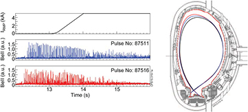
Figure 1. (Left) Timetraces showing the current in the error field correction coils used to apply an n = 2 non-axisymmetric field as well as the BeII emission indicating the ELM behaviour in discharges 87 511 (initial upper triangularity of  ) and 87 516 (initial upper triangularity of
  ); (Right) The last closed flux surface before the RMP is applied (dark blue line) and in the flat-top of the applied non-axisymmetric field for 87 511 (red line) and 87 516 where the 3d distortion is exacerbated by a deliberate increase in triangularity (cyan line).
Download figure:
Standard image High-resolution image2.2. Three-dimensional modelling of the effect of non-axisymmetric applied fields
In order to assess the effect that the n = 2 non-axisymmetric applied fields have on the plasma configuration and the edge stability, the plasma equilibrium has been calculated using the VMEC code [35], whilst the infinite-n ballooning stability is studied using the COBRA code [36]. In order to generate a 3d equilibrium, the plasma pressure and current density profiles are taken from an axisymmetric equilibrium reconstruction. The EFIT equilibrium is constrained by the pressure profile measured by the Thomson scattering diagnostic, then supplied to VMEC as an initial guess for the plasma shape, though the equilibrium is reconstructed in 3d with free boundary shape.
Figure 2 shows the change in the plasma boundary in both poloidal and toroidal space modelled by the VMEC when an n = 2 RMP is applied to a high collisionality plasma. The plasma shape, current and pressure profile predicted by the free-boundary VMEC equilibrium without RMPs applied match the axisymmetric EFIT equilibrium extremely well. This figure then shows the difference between a free-boundary VMEC equilibrium without an RMP applied and that with an n = 2 field applied. It is evident that the largest distortion predicted is at the low-field side midplane. Such midplane distortions are regularly observed in many tokamaks when RMPs are applied [37], though the 1 cm perturbation predicted in this case is within the error bars of the diagnostics available in this case. There is also a perturbation to the plasma shape at the top predicted by VMEC, though only a sub-cm distortion. VMEC is not able to handle strongly shaped plasmas due to numerical constraints. It is worth noting that in simulations of similar JET plasmas when n = 2 RMPs are applied, the non-linear MHD code JOREK, which can handle the separatrix geometry more realistically, predicts multi-cm distortions near the plasma top [38].

Figure 2. The plasma distortion [cm] compared to the axisymmetric configuration when an n = 2 field is applied to JET high-collisionality discharge 87 516 as modelled by 3d equilibrium code VMEC. There is a clear n = 2 distortion near the low-field side midplane, and also a milder change in the plasma shape at the top.
Download figure:
Standard image High-resolution imageThe change in the pedestal stability in the presence of this 3d distortion can also be assessed. Figure 3 shows the infinite-n ballooning mode growth rate as a function of the minor radius across the pedestal region for the case without an RMP applied, and then with an RMP applied in the toroidal position where the ballooning mode is most unstable. It is evident that the application of an RMP drives the mode more unstable, and indeed the critical pressure gradient for marginal stability of the mode decreases. This is consistent with the RMP inducing more frequent ELMs, as postulated in [32]. Whilst the change in the growth rate is relatively small, leading to only approximately 10% reduction in the critical pressure gradient for triggering a ballooning mode, this is consistent with the small changes in pressure gradient observed experimentally. It is not possible to infer the changes in nonlinear ELM behaviour such as the ELM period from linear stability modelling such as this, though the fact that ballooning modes become unstable at a lower pressure gradient is nonetheless consistent with the ELMs occurring more frequently.
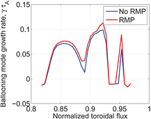
Figure 3. The infinite-n ballooning mode growth rate as a function of minor radius across the pedestal region with and without non-axisymmetric fields applied in JET high-collisionality plasma 87 516 as modelled by 3d stability code COBRA.
Download figure:
Standard image High-resolution image3. ELM triggering with vertical kicks
Vertical kicks are under consideration as an ELM pacing tool for ITER when operating below full current because they are non-resonant and so can be applied at any time in the discharge, notably in the current ramp-up when the q-profile is evolving. They can also be applied in helium plasmas (there is little experience of pellet-pacing in helium plasmas as a basis for ITER extrapolation). Vertical kicks have been established as a robust tool for pacing ELMs in JET [25, 26], and this demonstration predicates the consideration of kicks for pacing in Ip < 11 MA plasmas in ITER [5]. Recently, the mechanism by which vertical kicks trigger ELMs [39] has been studied in detail in JET [26]. It was found that there exists a critical threshold in the amplitude of the displacement which causes an ELM to be triggered, whilst the ELM triggering occurs for a range of kick velocities. This is consistent with a picture that the ELM is triggered by an increase in induced edge current located close to the separatrix, as suggested by predictions of kick triggering in ITER [40, 41].
In the studies of ELM pacing in this section and section 4, JET plasmas similar to that shown in figure 4 have been utilised. By optimising the strike point near to the cryopump throat, stationary conditions can be achieved for over 10s, with the normalised pressure, the confinement enhancement factor and the density as a function of the Greenwald density at ITER-relevant values, respectively  ,
,  and
and  .
.
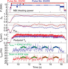
Figure 4. Typical JET discharges used for ELM pacing studies. The panes show respectively: (1) the injected power; (2) the normalised plasma pressure,  ; (3) the confinement enhancement factor, H98(y, 2); (4) the pedestal electron temperature; (5) and (6) the ELM frequency in the two discharges, showing the windows with kicks applied and when the kick triggering is effective the ELM frequency is at 43 Hz with a 5% modulation, as applied. It is evident that the discharge exhibits conditions similar to the ITER baseline targets,
  ,
,  , H98 (y, 2) = 1 in stationary conditions over 10s.
Download figure:
Standard image High-resolution image3.1. ELM pacing lag time
In order to probe the ability of vertical kicks to trigger ELMs at different kick sizes and at various times in the natural ELM cycles, kicks have been applied at very low frequency, ![${{f}_{\text{kick}}}\in [2,4]$](https://content.cld.iop.org/journals/0741-3335/58/1/014017/revision1/ppcfaa055fieqn016.gif) Hz, compared to the ELM frequency,
Hz, compared to the ELM frequency, ![$f_{\text{ELM}}^{\text{natural}}\in [25,45]$](https://content.cld.iop.org/journals/0741-3335/58/1/014017/revision1/ppcfaa055fieqn017.gif) Hz, with amplitudes varying from 10 Wb to 30 Wb (achieved by varying both the amplitude and the duration). Figure 5 shows a normalised histogram of the kick triggering likelihood as a function of the time since the previous natural type-I ELM. In this dataset the kicks have various amplitudes and durations. Whilst the likelihood of triggering an ELM in the first 5 ms of the natural ELM cycle is low, it is nonetheless possible.
Hz, with amplitudes varying from 10 Wb to 30 Wb (achieved by varying both the amplitude and the duration). Figure 5 shows a normalised histogram of the kick triggering likelihood as a function of the time since the previous natural type-I ELM. In this dataset the kicks have various amplitudes and durations. Whilst the likelihood of triggering an ELM in the first 5 ms of the natural ELM cycle is low, it is nonetheless possible.

Figure 5. A normalised histogram showing the ELM triggering efficiency by vertical kicks occurring at different times in the natural ELM cycle. This data is collected from over 150 kicks of varying amplitude and duration.
Download figure:
Standard image High-resolution imageFigure 6 shows the probability of triggering an ELM depending on the amplitude of the vertical kick and the time since the previous natural ELM based upon over 150 individual kicks at very low frequency. It is evident that the likelihood of a vertical kick triggering an ELM increases with time following the previous ELM, and also with kick size. The typical type-I ELM cycle is widely understood to consist of a gradual increase in the pedestal pressure gradient and a commensurate increase in the edge current density until the plasma parameters reach those for triggering a peeling-ballooning mode, manifest as an ELM [1]. After the ELM, the pedestal pressure gradient and current density relax so that the plasma edge is stable and far from the instability boundary [2, 3]. This is consistent with the need for a larger perturbation to the pedestal parameters in the form of a larger vertical kick amplitude in order to induce sufficient current to invoke a peeling-ballooning mode to grow.

Figure 6. The probability of triggering an ELM by a vertical kick as a function of the kick amplitude and the time since the previous natural ELM. The data is collected from over 150 kicks at very low frequency (2–4 Hz) during plasmas like that in figure 4.
Download figure:
Standard image High-resolution image3.2. Dependence of ELM pacing with kicks on the global plasma pressure
It has been shown that the efficiency of kicks in triggering ELMs depends on the pedestal parameters [26]. When the pedestal temperature was increased by enhanced auxiliary heating at approximately constant pedestal density, the kick amplitude required to invoke an ELM reduced, concomitant with the higher temperature resulting in more edge current, and thereby decreasing the current which the vertical kick needed to induce to reach the peeling-ballooning boundary. However, as the auxiliary heating was increased, the global plasma beta also increases, and it is known that this affects the pedestal stability. Both modelling [42, 43] and experiment [44] indicate that an increase in the global pressure stabilises ballooning modes. In order to test how this affects the critical kick size required for triggering ELMs, two JET plasmas with the same pedestal temperature, but different global normalised pressure were established by varying the plasma current, magnetic field and auxiliary heating. It is found that when the pedestal temperature matches, larger kicks are required to trigger ELMs when the global normalised pressure is larger. Given that the pedestal temperature and collisionality are the same, one might expect that the current which needs to be induced by the vertical displacement would be the same. To investigate the stability of these plasmas, simulations have been performed with the linear ideal MHD code, ELITE [45]. We vary the normalised pressure gradient, α, and current density, j, around the experimental conditions, in each case creating a new equilibrium with the HELENA code [46] before assessing its stability to finite-n peeling-ballooning modes. Here, the normalised pressure gradient is defined as
where V is the volume enclosed by flux surface with poloidal flux, ψ, p is the pressure and R0 is the major radius of the geometrical plasma centre. This method is described in detail in [47]. The plasma boundary shape is taken from EFIT reconstruction and held fixed, whilst the electron temperature and density pedestal heights are taken from tanh fits to the Thomson scattering measurements just before an ELM. The ion temperature is assumed to be equal to the electron temperature.
Figure 7 shows the peeling-ballooning marginal stability boundary as calculated by ELITE for two JET plasmas with different normalised pressure,  . When the core pressure increases the ballooning modes are stabilised due to enhanced Shafranov shift [43, 44], increasing the critical pressure gradient and current density at which an ELM is triggered. This explains why a larger kick is needed to trigger an ELM in a plasma with higher core pressure compared to a comparable plasma with the same pedestal height—the larger core pressure has stabilised the ballooning boundary, requiring more induced edge current to reach the critical threshold and trigger an ELM.
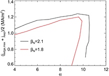
Figure 7. ELITE simulations showing the peeling-ballooning stability boundaries for a JET plasma with different normalised pressure. At higher  , the stability boundary is at a higher critical normalised pressure gradient, indicating that a kick early in the ELM cycle will require a larger displacement amplitude to reach the stability boundary and trigger an ELM.
Download figure:
Standard image High-resolution image4. ELM triggering with pellets
ELM control via pellets relies upon the inverse dependence of the ELM energy loss on the ELM frequency, such that as the ELMs are paced at higher frequency,  reduces to the required level [27]. There are a number of challenges for robust ELM control by pellets in ITER, not least that the frequency enhancement must be achieved at high levels (more than a factor of ten) whilst maintaining good core confinement and, even more critically, concomitant with a sufficient reduction in the peak heat flux incident on the divertor plates. Previous results from JET [21] and ASDEX Upgrade [20] indicated that there was a minimum time after a natural ELM at which a pellet could trigger an ELM—a so-called 'lag time'. This has serious implications for ITER since the presence of such a lag before pacing can be achieved by pellets suggests a maximum ELM frequency, which may preclude the necessary frequency enhancement for protection of the plasma facing components.
4.1. ELM pacing lag time
Pellets from both the vertical high-field side and the low-field side have been used to test whether this 'lag time' can be negated in JET plasmas similar to the pulse shown in figure 4. When large pellets are injected the triggering efficiency is very high, whereas small pellets are considerably less likely to trigger ELMs [21]. Here, large pellets have 22– deuterons when formed, though a large proportion do not remain fully intact upon plasma entry, whereas small pellets are
  deuterons. Very few large pellets arrive intact, and there are many fragmented pellet arrivals in the plasma, as illustrated in figure 8. This example shows two broken pellets arriving in a JET discharge; the first is two relatively small pellet fragments arriving 9.4 ms after a natural ELM whilst the latter consists of two large fragments arriving only 3.8 ms after a natural ELM. In both cases an ELM is triggered promptly by the arrival of each fragment of the pellet.
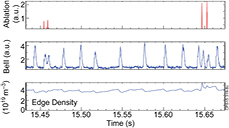
Figure 8. JET discharge 86 983 showing the pellet ablation marker from the fast-framing camera, the BeII emission indicating the ELM behaviour and the edge density when pellets are injected. On two occasions the pellet fragments and reaches the plasma in two pieces, which trigger successive ELMs promptly, including within 4 ms of a natural ELM.
Download figure:
Standard image High-resolution imageA comparison of the time since the previous ELM for both natural ELMs and pellet-triggered ELMs is shown in figure 9. In the same way that kicks above a threshold can trigger ELMs any time after the previous ELM (as discussed in section 3), it is evident that pellets can trigger ELMs at any point during the natural ELM cycle provided they are sufficiently large. This is encouraging news for ITER in the sense that the achievable ELM frequency by pellet pacing can in principle reach the required frequency enhancement factors provided the pellets are sufficiently massive and injected with sufficient speed to penetrate deep enough into the pedestal. However, a demonstration that high-frequency ELMs can be triggered without a degradation in pedestal performance remains necessary.
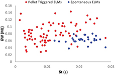
Figure 9. A database of the energy loss per ELM plotted against the time since the last ELM for a range of pedestal conditions and plasma masses, indicating that spontaneous natural ELMs only occur after a critical time since the previous natural type-I ELM, whereas pellet-triggered ELMs can occur at any point in the ELM cycle.
Download figure:
Standard image High-resolution imageIt has been shown previously that the ability of pellets to trigger ELMs depends upon both the pellet mass and the pellet speed [21]. When applying low frequency pellets compared to the natural ELM frequency, it is possible to consider how the pellet triggering efficiency also depends upon the time during the natural ELM cycle, as done for vertical kicks in section 3. Figure 10 shows the triggering probability for different pellet mass assessed by a fast visible-light framing camera and for pellets arriving at different times in the natural ELM cycle. It is evident that when the pellet arrives late in the natural ELM cycle, an ELM is always triggered for the pellet masses considered here, whereas earlier in the ELM cycle, only exceptionally large pellets have a good probability of triggering ELMs.
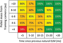
Figure 10. The pacing efficiency of pellets as a function of both the time since the previous natural ELM and the mass of the pellet as inferred from the fast framing camera.
Download figure:
Standard image High-resolution image4.2. Dependence of ELM pacing with pellets on the pedestal temperature
As well as the pellet mass and the time since the previous natural ELM, the ELM triggering by pellets also depends upon the pedestal conditions. Figure 11 shows a normalised histogram of the triggering efficiency for over 350 pellets with a range of masses, from both low-field and vertical high-field injection lines and at various points in the ELM cycle as a function of the temperature at the pedestal top. It is evident that for hotter pedestals, the triggering efficiency drops slightly, though it still remains high for these massive pellets. This could be due to a more rapid ablation of the pellet meaning the pellet does not penetrate sufficiently far into the pedestal to stimulate an ELM; it could be that the hotter pedestal temperature comes with higher injected auxiliary heating, which raises the core pressure and stabilises the ballooning boundary (as discussed in section 3), necessitating a larger perturbation to trigger an ELM. The effect of pellets on ballooning stability for different pedestal conditions has been studied in JOREK [48] and comparison with experiments will be pursued in the future.
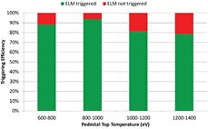
Figure 11. The pacing efficiency of pellets for a range of pedestal conditions.
Download figure:
Standard image High-resolution image5. Utilising ELM pacing for avoidance of tungsten accumulation
Since the installation of the ITER-like Be/W wall in JET, the typical plasma confinement has been degraded when compared to the carbon wall [49]. This can, in part, be attributed to operating with higher levels of deuterium fuelling in order to protect the divertor from excessive heat loading in order to avoid ingress of tungsten into the plasma [50]. Indeed, operating with the ELM frequency above the natural ELM frequency to avoid tungsten accumulation may be a more acute need for ELM control in the early operation of ITER at lower field and current than heat load mitigation [5]. Therefore, it is important to demonstrate ELM pacing techniques which can keep the ELM frequency above the natural ELM frequency to avoid tungsten accumulation, avoiding the requirement to increase the gas dosing and so providing a possible route to improving pedestal performance and confinement. This has been attempted in JET using ELM pacing by both pellets and vertical kicks, though the scenario performance utilising these pacing techniques has not yet been optimised.
A closed loop ELM frequency controller has been implemented on JET using gas injection as the actuator and shown to work well at ELM frequencies in the 15–40 Hz range [51]. The controller has allowed successful operation near the minimum acceptable ELM frequency where good plasma confinement can be achieved. The ELM frequency controller has been applied in conjunction with pellet injection in order to minimise the gas dosing required but at the same time maintain the desired ELM frequency even when pellets fail to trigger ELMs. Figure 12 shows a case when small 'pacing-sized' pellets have been used to pace the ELMs in conjunction with real-time control on the gas to maintain a requested ELM frequency. Even the small pellets used in this plasma were able to successfully trigger ELMs over a period of nearly two seconds, enabling the gas injection to be turned off. The ELM pacing by small pellets shown here is not fully effective, and so the ELM frequency drops below the requested rate, at which point the closed loop controller requests an increase in gas injection in order to keep the paced ELM frequency sufficiently high. Nonetheless, this shows promise that ELM pacing by pellets could offer a route to a sustained plasma with much lower gas fuelling, which with optimisation of the ELM frequency and pellet mass may lead to improved confinement simultaneous with avoidance of core tungsten accumulation [52].

Figure 12. Timetraces for JET discharge 84 693 showing respectively: (1) the injected NBI power, the stored energy and the injected pellet timings; (2) the bulk radiated power; (3) the requested ELM frequency and the measured ELM frequency and (4) the gas injection rate. It is evident that for 1.5s the pellets successfully trigger the ELMs and so the injected gas is stopped.
Download figure:
Standard image High-resolution imageVertical kicks have also been utilised for avoidance of tungsten accumulation at lower gas injection rates. Figure 13 shows two JET discharges with a significant reduction of the gas injection rate in the middle of the current flat-top. In the case without ELM pacing, the natural ELM frequency drops to a few Hertz and the radiated power increases rapidly, eventually leading to a termination of the discharge due to an accumulation of tungsten in the plasma core. However, when vertical kicks are applied with sufficient amplitude, the ELM frequency can be sustained at a high rate when the gas injection is reduced, allowing stationary conditions to be maintained. Once again, this demonstrates that ELM pacing by vertical kicks can be utilised in JET for the avoidance of tungsten accumulation, though the optimisation of plasma confinement has not yet been performed.

Figure 13. Timetraces for two JET discharges with a step down in the gas fuelling. Shown respectively are: (i) the gas injection rate for discharge 86 993 which does not have vertical kicks in the low fuelling part, and discharge 87 120 which has large amplitude kicks when the gas injection is dropped; (ii) the edge density for both discharges; (iii) the NBI power; (iv) the radiated power, showing a radiative collapse in the case with low gas fuelling and no ELM pacing; (v) the applied kicks for discharge 86 993, with only small kicks before the gas is dropped; (vi) the applied kicks for discharge 87 120, with large kicks across the transition in gas fuelling; (vii) the BeII emission showing the ELM behaviour in 86 993, demonstrating the low natural ELM frequency at low gas fuelling and (viii) the BeII emission showing the ELM behaviour in 87 120, demonstrating that vertical kicks can sustain a high ELM frequency at low gas fuelling, sustaining the plasma discharge.
Download figure:
Standard image High-resolution image
6. Discussion and conclusions
ELM control is very likely to be required for the successful operation of ITER, initially via ELM pacing for avoidance of tungsten accumulation in the non-active, low-current phase, and later for Type-I ELM mitigation or suppression in the high power, high confinement plasmas. However, for all flavours of ELM control there remain challenges in understanding how the actuators control the ELMs in order to reliably extrapolate to ITER—these are outlined in more detail in [27] and [30]. Improvements in understanding have been addressed here in some areas for three of the main ELM control actuators considered for ITER.
It has been found that the plasma shaping affects ELM mitigation with RMPs in high collisionality, high Greenwald fraction plasmas. The application of an n = 2 RMP changes the magnetic topology in certain toroidal positions, which is found to affect the edge stability, degrading the local ballooning stability. This decrease in the critical pressure gradient required to destabilise infinite-n ballooning modes is consistent with the ELM mitigation observed when RMPs are applied. Furthermore, when the plasma triangularity is deliberately increased in addition to the changes in plasma shape incurred due to the non-axisymmetric fields, the ELM mitigation experienced in JET plasmas is enhanced with higher frequency ELMs with a lower energy loss per ELM.
Both vertical kicks and pellets have been used to pace ELMs in JET. It is observed that provided the perturbation is sufficiently large, an ELM can be triggered at any time in the natural ELM cycle, implying that there is no fundamental limitation to the achievable ELM frequency enhancement factor by these pacing techniques. The likelihood of ELM triggering by a vertical kick increases with both the kick amplitude and the time since the previous ELM. The critical kick amplitude required for ELM triggering also depends on the plasma parameters; for instance, it has been shown that a higher core pressure stabilises the ballooning modes, thus necessitating a larger kick size to successfully trigger an ELM.
Finally, ELM pacing for avoidance of core impurity accumulation has been successfully demonstrated on JET to support development of high performance scenarios as well as in preparation for early ITER operation. Pellet pacing has been used to successfully replace gas injection as a means for sustaining the ELM frequency at the level required to avoid tungsten accumulation in the plasma core. Similarly, vertical kicks have been shown to allow stationary plasma conditions when the gas dosing is dropped significantly in plasmas where the absence of ELM pacing would otherwise result in tungsten accumulation and ultimately radiative collapse and plasma termination. These improvements in the understanding of ELM control, together with demonstration of the utilisation of ELM pacing, support the implementation of these control actuators in ITER.
Acknowledgments
This work has been carried out within the framework of the EUROfusion Consortium and has received funding from the Euratom research and training programme 2014-2018 under grant agreement No 633053 and from the RCUK Energy Programme (grant number EP/I501045). To obtain further information on the data and models underlying this paper please contact PublicationsManager@ccfe.ac.uk. The views and opinions expressed herein do not necessarily reflect those of the European Commission.