
Abstract
High temperature superconducting (HTS) tape can be cut and stacked to generate large magnetic fields at cryogenic temperatures after inducing persistent currents in the superconducting layers. A field of 17.7 T was trapped between two stacks of HTS tape at 8 K with no external mechanical reinforcement. 17.6 T could be sustained when warming the stack up to 14 K. A new type of hybrid stack was used consisting of a 12 mm square insert stack embedded inside a larger 34.4 mm diameter stack made from different tape. The magnetic field generated is marginally higher than the previous trapped field record achieved by a bulk HTS magnet and 30% greater than previously achieved in a stack of HTS tapes. Such stacks are being considered for superconducting motors as rotor field poles where the cryogenic penalty is justified by the increased power to weight ratio. The sample reported can be considered the strongest permanent magnet ever created.
Export citation and abstract BibTeX RIS
1. Introduction
High temperature superconducting (HTS) tape produced commercially can sustain large persistent currents in their micron thick superconducting layers which have the chemical composition, (RE)Ba2Cu3O7−δ or simply (RE)BCO, where RE is a rare earth metal, most commonly Y or Gd or a combination of both. Although primarily manufactured by a number of global suppliers for use in cables and coils, when cut into pieces and stacked, composite bulks can be formed, which can trap high magnetic fields despite only containing a few percent HTS by volume. Most previous trapped field magnets have taken the form of bulk (RE)BCO [1, 2], grown via top seeded melt growth, where the volume fraction of HTS is typically >90%. This means that very high engineering current densities are possible, which has allowed trapped fields of up to 17.6 T at 26 K [1], the previous record field for a trapped field magnet. However, their limiting property is mechanical strength due to cracks in the brittle ceramic HTS. These arise due to the large tensile stresses inside the sample resulting from Lorentz forces acting between supercurrent and the corresponding pinned flux vortices. External mechanical reinforcement is essential to trap fields >10 T in a bulk, [2–5], a stainless steel band [1] and resin impregnation with a carbon fibre wrapping [2], had to be used for the previous two bulk records. Even then, it is common for a number of samples in a batch to break when trapping such high fields.
The large metallic volume fraction and layered structure of stacks of HTS tape have numerous advantages for trapping very high fields and for applications where such composite bulks could be used as permanent magnets. The four main advantages are as follows. (i) Their geometry is very flexible and they can be easily machined allowing many shapes [6]. (ii) The superalloy substrates, which account for more than 85% of the volume fraction, have a very high tensile strength, which means no external mechanical reinforcement is needed to counter Lorentz forces at high trapped fields. (iii) The superconducting properties are generally consistent throughout the volume of the stack and defects in individual layers are smoothed out in the trapped field profiles [7], meaning that different stacks made from the same batch of tape have the same performance. (iv) The silver stabilizer layer on top of the HTS layer provides thermal stability which helps dissipate heat generated inside the stack and supresses flux jumps [8, 9].
Initial experiments on trapping field in stacks of HTS tape were performed in liquid nitrogen at 77.4 K [10] and also using pulsed field magnetization [11]. However, lower temperatures achieved higher trapped fields [8, 11–13] in addition to using field cooling magnetization which achieves the highest possible trapped field by the application of a slowly decreasing applied field. Rapid progress has been achieved (figure 1), and as the critical current of commercially produced tapes steadily improves, further progress is inevitable.

Figure 1. Trapped field records for stacks of HTS tape. Field cooling magnetization used and field measured between two stacks according to convention [8, 10–13].
Download figure:
Standard image High-resolution image2. Stack composition and magnetization procedure
2.1. Stack fabrication and composition
The magnetic field generated by a trapped field magnet is fundamentally limited by two factors due to Ampere's law; the diameter of the magnet (assuming the height is unconstrained) and the engineering current density Je (A m−2). The previous trapped field records for stacks of tape [11–13] were all achieved using 12 mm or 10 mm square stacks as this is the standard width of tape most suppliers produce. The thin 30 μm substrate used by SuperPower Inc. has allowed for significant increases in Je. Only American Superconductor (AMSC) currently produces wider tape routinely, which is then typically slit down to standard 10 or 4 mm wide HTS wire [14]. To combine the advantages of the highest Je stacks with a larger width stack, a hybrid design was used. A high Je stack made from SuperPower tape was embedded inside a lower Je, but larger size stack made from 46 mm wide AMSC tape. The geometry and composition of the hybrid stack is shown in figure 2.
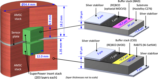
Figure 2. Composition and geometry of the hybrid stack consisting of a 12 mm square stack made from SuperPower tape inside a larger cylindrical stack made from AMSC tape.
Download figure:
Standard image High-resolution imageThe SuperPower stack was made from tape with specification SP12030 AP and composition (Y,Gd)1+xBa2Cu3O7−δ with 7.5% Zr added [15]. The properties of both tapes are summarised in table 1 which shows that the AMSC tape had almost three times lower engineering current density largely due to the much thicker substrate. The tensile yield strengths of the tape substrates determine the trapped field mechanical limit. HTS tape can usually go beyond its elastic limit with only a few % degradation in Ic [16], but for the purposes of trapped field magnets we can consider the yield stress as the maximum acceptable stress. The SuperPower tape substrate, Hastelloy C276, has a tensile yield strength of 700 MPa and the AMSC substrate, Ni–5at%W, has a yield strength of 257 MPa [16]. Before constructing the sample and performing the experiment, detailed modelling was performed to explore the hybrid stack concept, predict trapped fields at all temperatures, determine the stack dimensions to be used and crucially to predict whether the stack would survive the predicted mechanical stresses without external reinforcement [17]. This modelling predicted a trapped field of 31.5 T to reach the mechanical limits of the stack by scaling real Je(B, 10 K) estimates by a factor and doing a parametric sweep of this factor. The AMSC tape is the limiting mechanical component for the hybrid stack. This shows that mechanical properties are not a limiting factor for the current stacks.
Table 1. Summary of HTS tape properties.
| Property | SuperPower | AMSC |
|---|---|---|
| Ic (A/cm-w) 77 K, self field | 450 | 391 |
| Je (A m−2) | 1.32 × 10⁹ | 4.49 × 10⁸ |
| Tape thickness (μm) | 34 | 87 |
| Substrate | Hastelloy C276 | Ni–5at%W |
Although the AMSC tape had a width of 46 mm, the maximum external diameter of the stack was limited by the bore of the superconducting magnet. The stack was therefore machined to an external diameter of 34.4 mm using the precise technique of spark erosion as used previously [6], resulting in the components and final sample shown in figure 3.

Figure 3. (a) Components of one half of the American Superconductor stack after spark erosion machining. (b) Final hybrid stack fully assembled.
Download figure:
Standard image High-resolution image2.2. Instrumentation and measurement procedure
A stainless steel sensor plate was placed in the axial centre of the hybrid stack and contained three Arepoc model LHP-MP cryogenic Hall probes at positions x = 0, 6 and 13.5 mm away from the centre, where x is equal to radius from the stack axis along the direction of the sensors. The 6 mm position lies exactly at the edge of the insert stack. Due to the large number of stack layers, the trapped field is expected to be highly symmetric [18] and so it is sufficient to have Hall probes only on one side. These probes are low sensitivity and have very high linearity (<2% deviation at 18 T), so are specifically suited to trapped field measurement and are reliable after thermal cycling. The relatively large package size (about 5 mm in width) means no more than 3 could fit between the centre and sample side. Reliability of the field measurement was chosen over resolution of the trapped field profile. A fully calibrated Lakeshore Cernox CX-1070 temperature sensor was also embedded in the sensor plate. The thickness of the plate was chosen to fully carry the large compressive force between the stacks. The stacks and sensor plate were held together by insertion in a stainless steel cylinder which applied a gentle axial compression to hold the components together.
The Hall probes were fully calibrated once at 100 K up to 18 T in the superconducting magnet before the magnetization tests. They were driven with an AC current of 17.5 mA at 321 Hz using a Stanford Research Systems voltage controlled current source, and the Hall voltages were measured using lock in amplifiers. Lock in amplifiers (SR865) were used to generate a 0.35 V AC signal (321 Hz) supplied to a voltage controlled current source (Model C5580) which had a gain of 50 mA V−1 (17.5 mA supply current). Field cooling magnetization was used to trap field using an 18 T low temperature superconducting magnet (SCM-2) at the National High Magnetic Field Laboratory (Florida State University), which is the same magnet used for the previous trapped field record in bulks [1]. Modelling before the experiment [17] predicted a trapped field of 18.0 T at 10 K for the hybrid stack (assuming a saturated sample) which informed the magnet choice and applied fields.
Sample temperature was controlled by varying power to a heater that is immersed in a pool of liquid helium. The resulting variable flow of helium vapour determined the temperature of the sample.
3. Results and discussion
The hybrid stack was cooled to 11 K in the presence of a 17.9 T applied field. The field was then ramped down at a rate of 15.5 mT min−1. The measured fields are shown in figure 4. Given the relatively low temperatures, flux jumps are a concern and do occur in stacks of HTS tape if too high ramp rates are used as was seen when testing the SuperPower stack alone and in previous tests [13]. Therefore, a conservative ramp rate was used to minimise the risk of flux jumps. The sample temperature proved difficult to completely stabilise below 15 K resulting in a drift, partly because the sample is continuously generating heat during ramp down as flux leaves the sample. Heater settings were chosen to deliberately ensure a negative rather than positive drift to prevent a massive flux avalanche. The final sample temperature of 8 K can be considered the temperature at which the field was trapped, with subsequent warming, as reported later, revealing what would have been trapped at temperatures higher than 8 K. The relatively flat line of the central Hall probe indicates that the sample centre is very well shielded from changes in the external applied field which suggests that the sample was either not saturated or only just saturated. The trapped field at the centre of the stack (x = 0) was measured to be 17.66 T at the end of the ramp. Before the ramp down, the off-centre hall probes recorded a field higher than the applied field by 0.11 T for x = 6 mm. This is entirely expected due to the magnetic Ni–W substrate of the AMSC tape (92% volume fraction) which was incorporated into FEM models. The model also predicted the effect of the magnetic substrates on central trapped field after ramp end. Due to the non-magnetic void at the insert, flux generated by the currents are slightly diverted away from the insert resulting in a reduction of central field of 1.1% at 10 K and 6.4% at 77 K. However, due to the enhanced fields between the AMSC stacks (x > 6 mm), the total flux crossing the sensor plate is increased by around 2%. Therefore, the magnetic substrate is not detrimental for applications where flux is linked from a stack to another magnetic object close by such as motor back iron.
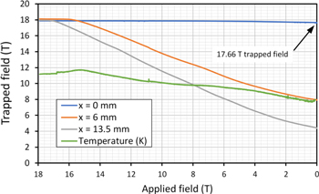
Figure 4. The magnetic field measured using the three Hall sensors during ramp down of a 17.9 T applied field. The temperature drifted down to 8 K during the ramp. The trapped fields are the measured fields at the end of the ramp (applied field = 0 T).
Download figure:
Standard image High-resolution imageAfter the ramp end, the sample was slowly warmed up to 16 K at a rate of 0.1 K min−1 as shown by the purple data in figure 5, to determine the maximum trapped field at slightly higher temperatures. Faster warm up rates caused the stack to quench after the 15 K test. Due to limited magnet time, the warm up from 8 K could not extend all the way to 77 K, however prior tests leading up to the one at 8 K give an overall picture of the trapped field possible at different temperatures as summarised in figure 5. The trapped fields achieved at 15 K, 30 K and 77.4 K are also shown for which the applied fields were 14.6 T, 13.8 T and 2.5 T respectively with ramp rates of 30, 50 and 300 mT min−1 used respectively. After trapping a field of 10.4 T at 30 K, the sample was warmed up to 90 K (orange data) showing the maximum field that can be trapped at all higher temperatures. This data set starts at a lower trapped field than the data point for the field at the ramp end. This is due to flux creep at 30 K for 150 min after the ramp ended before the warm up was started. Based on all the trapped field data for the hybrid stack, a quadratic interpolation can be made (black dotted line) to give an approximation of the maximum trapped field possible between 10 and 35 K. This interpolation suggests that the hybrid stack was not fully saturated for the 3 tests at 8, 15 and 30 K with a trapped field greater than 18 T possible below 15 K if a higher applied field was used. However, based on experience, thermal instability and flux jumps are far more common if using a magnetizing field higher than necessary to saturate the sample. This justifies a more cautious approach to maximise informative results given limited magnet time.
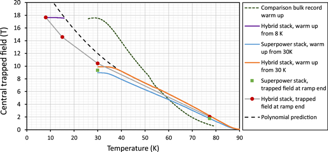
Figure 5. Summary of the experimental trapped field results for the hybrid stack and the SuperPower stack on its own. The solid data points indicate the trapped field at the end of an applied field ramp for a particular temperature. The solid lines are trapped field data as the sample is warmed up from the corresponding temperature. The dashed lines are a prediction of the maximum trapped field of the hybrid stack based on a quadratic interpolation of the orange and purple data points, and previous bulk trapped field data.
Download figure:
Standard image High-resolution imageIn addition to the hybrid stack, the SuperPower stack was magnetized on its own. Figure 5 shows the trapped field at 30 K and subsequent warm up to 90 K. The trapped field of 9.3 T at the end of the ramp is 90% of that achieved for the hybrid stack, indicating that the insert stack is making the major contribution to the trapped field in the hybrid stack. The 9.3 T value is 13% higher than the interpolated trapped field of a similar previous SuperPower stack made from the same type of 30 μm substrate tape [13]. This is partly because the rated Ic of 540 A is higher than the previous tape and due to a smaller sensor plate gap (1.35 mm compared to 2.0 mm).
For comparison, the trapped field with warm up for the previous bulk record [1] has been plotted. The bulk trapped field is higher than the stack below 55 K but lower above 55 K. This could be due to different Jc(B, T) forms, degradation of the bulk material after ∼50 K upon warming and relaxing of tensile stress, or a high thermal gradient between the temperature sensor and bulk interior. The apparent increase in trapped field after initial warming can be ignored as it has been attributed to Hall voltage drift.
The trapped field profiles at ramp end are shown in figure 6. Due to the higher engineering current density of the insert stack, the trapped field has a steeper gradient in the central region. The profiles suggest that the trapped field at 15 K is not saturated which is confirmed by the large gap between the trapped field data point for 15 K in figure 5, and the trapped field achieved at the same temperature when warming up the 8 K test (purple data). For comparison, the trapped field profile for the SuperPower stack alone at 30 K is shown in figure 6 and indicates that whilst the central trapped field is not much less than that achieved by the hybrid stack, the total trapped flux is much less. This can be more fully visualised by modelling results shown in figure 7 which also illustrate the forces which lead to large radial tensile stress and a compressive stress of 16 tonnes at the sensor plate [17]. The models used a stationary solver in the AC/DC module of COMSOL, and a specified Je(B) function as a saturated current density based on tape Ic data. Further details can be found in [17]. The models predict that the insert stack contributes 85% to the central trapped field which is reasonably close to the 90% experimental value. The reason the insert stack contributes most to the measured field, is partly because the SuperPower tape has almost three times Je, and partly because it is closest to the region at which field is measured. The latter reason relates to a diminishing increase in central trapped field with sample diameter for any trapped field magnet. Modelling also predicted the fields that would be measured for only one stack rather than a pair which is more relevant for applications. For the hybrid stack, the field is predicted to be 58% (10.2 T) of the double hybrid stack and 54% for a single SuperPower stack compared to double SuperPower stack. Whilst much lower, the achievable fields are still significant enough for target applications.
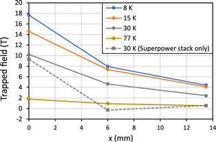
Figure 6. Trapped field profiles for the hybrid stack at various magnetization temperatures. The 15 K profile is not saturated. The 30 K result for the SuperPower stack alone is included for comparison, illustrating the majority contribution it makes to the central field.
Download figure:
Standard image High-resolution image
Figure 7. Modelling of the critical state of (a) the hybrid stack and (b) the insert stack only, after field cooling magnetization at 10 K assuming axi-symmetric symmetry. (c) Example deformation (exaggerated by 2000) and von Mises stress due to compressive axial and radial tensile stress.
Download figure:
Standard image High-resolution imageAfter magnetization, the fields were recorded for a period of at least 30 min to measure flux creep of the trapped field. Figure 8 shows that the creep rates are lower for lower temperatures which agrees with previous experiments [8, 13] and that the creep is approximately logarithmic after the first ∼500 s which is expected [19]. The creep of the central trapped field was very low for 15 and 8 K (less than 0.1% decay after 30 min), however the creep of the field at the edges of the sample is higher as illustrated by figure 8(b) as flux first begins to leave the sample from the outer edges. Such flux creep is not a concern for applications because the decay in-field is logarithmic and can be effectively eliminated by lowering the sample temperature a few Kelvin below the magnetization temperature [20, 21]. The data for the previous bulk experiment [1] is also plotted for comparison and shows a creep rate between the 15 and 30 K as expected given the bulk temperature was in between the two at 26 K. A more detailed comparison would require using the same temperatures, but creep rates for bulks and stacks can broadly be considered similar.
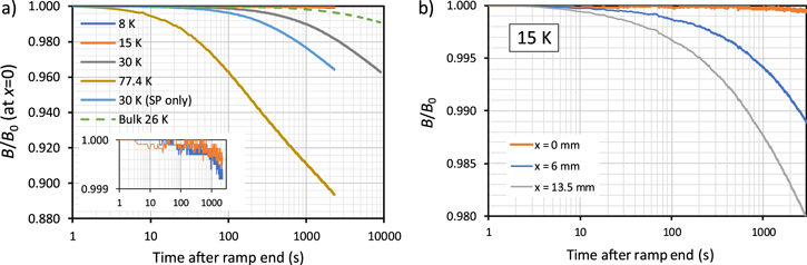
Figure 8. (a) Flux creep for the normalised trapped field at the sample centre after magnetization of the hybrid stack at various temperatures. Results for the SuperPower stack only, at 30 K are included for comparison. B0 is the trapped field at t = 1 s. (b) Example flux creep for the normalised trapped field at the three different positions for the hybrid stack.
Download figure:
Standard image High-resolution image4. Summary
The maximum trapped field of 17.7 T is slightly higher than the previous record trapped field achieved in a GdBCO bulk [1] making it the strongest trapped field magnet to date. The result is significant given that it is a large increase from the previous trapped field of 13.4 T [13] achieved by a stack of HTS tapes and marks a critical point in the development of these relatively new composite bulks. The hybrid sample could be quenched and reused without destruction or obvious degradation which is often not the case for bulk superconductors trapping very high fields. The sample had relatively predictable trapped field and due to the consistency of HTS tape, another stack made from the same tape can reliably be expected to trap the same field.
Although the insert of the hybrid stack produced most of the central trapped field, the outer AMSC stack still contributed significantly to the total trapped flux which is as important as the peak trapped field for many applications. Expected improvements in tape Ic should allow a similar trapped field to be achieved at temperatures higher than ∼15 K in future. Such stacks of HTS tape are being investigated as rotor field poles for a superconducting 1 MW motor in the EU project ASuMED: Advanced Superconducting Motor Experimental Demonstrator (grant No. 723119), given their ability to act as compact sources of high magnetic field.
Acknowledgments
The authors would like to acknowledge the financial support of the UK Engineering and Physical Sciences Research Council (EPSRC, grant EP/P000738/1). A portion of this work was performed at the National High Magnetic Field Laboratory, which is supported by National Science Foundation Cooperative Agreement No. DMR-1157490 and the State of Florida. Raw data, analysis and Hall probe calibration files can be found online at: https://doi.org/10.17863/CAM.20979.
Appendix A: Error estimate for measured field
The test which generated the highest trapped field involved an applied field of 17.90 T but the sample was not saturated as outlined in the main text. The previous trapped field record of 17.6 T for a bulk superconductor [1], was achieved using an applied field of 17.80 T and exactly the same superconducting magnet system. The sample for this test was also not saturated. Therefore, it follows logically that the maximum trapped field reported in this paper is higher than the previous test, and indeed it would be difficult to explain if the trapped field measured was lower than 17.6 T (for a 17.90 T applied field and a sample found to be unsaturated). Despite this clear plausibility argument, there are a number of sources of error when measuring the central trapped field that should be considered in relation to the 17.66 T trapped field value to validate the claim that this is the highest field yet generated by a trapped field magnet.
Hall probe radial positional error would only contribute a positive error to the field value as the field at the geometric centre is highest and it is this central field which is considered as the 'trapped field'. The Hall probe central position has a radial position error of up to +0.11 mm. However, given the sample was not saturated for the 17.66 T test, the field over this radius is very likely flat profiled. Therefore, this error can be ignored. The error due to the Hall probe being tilted at an angle (by 1° at most) can also be ignored assuming that any tilt during tests was also present during the Hall probe calibration performed with the Hall probes already installed in the sensor plate and sample holder a few days before the field cooling magnetisation. There was a small measurable change in the sensitivity of the Hall probes when cooling from 100 K (the temperature at which calibration was conducted) and 10 K in the presence of the 17.9 T applied field. This was accounted for by calculating temperature dependent scaling factors for the 17.7 T experiment which resulted in a very small adjustment of 0.02% for the central field, but larger adjustments for the other two probes. Errors in the Hall voltage due to signal noise can be estimated at ±0.05% corresponding to ±9 mT in-field. However, all field were recorded through continuous sampling which diminishes this error and sensitivity calibration curves are based on an interpolated fits to field sweeps consisting of 4000 hall voltages data points. Since the Hall probes were self-calibrated at 18 T, a critical parameter is drift in the lock in amplifiers and the voltage controlled current source, which are considered minimal. Any non-negligible drift would be detectable during the very long magnet sweeps after data analysis which was not the case. The error in the applied magnet field is <0.05% and can therefore be ignored especially considering that it would be a systematic error also present in the previous 17.6 T trapped field measurement record which was achieved using the same magnet system.
Appendix B: Measurement of the critical current of the tape used
To determine the in-field behaviour of the HTS tapes used in the hybrid stack, critical current tests were performed using a custom designed critical current test rig at Karlsruher Institute for Technology. This involved cutting a piece of HTS tape to form a 2 mm wide bridge to lower the critical current of the sample. The critical current was measured using the standard four-point probe technique and the sample rod was mounted in a helium gas flow cryostat where temperature in the sample space can be stabilized between 2 and 200 K. The cryostat was also equipped with a superconducting split coil magnet and magnetic fields of up to 6 T can be applied. All measurements were done at maximum Lorentz force and the magnetic field was directed perpendicular to the surface of the tape. The reason for cutting the bridge width down to 2 mm, was the lack of copper stabiliser on the samples which lowers thermal stability and leads to sample burn out for high currents. This is particularly a problem at lower temperatures due to increased critical current and lower heat capacities. The bridge width was determined to an accuracy of ±0.1 mm which is the main source of error for the Ic values leading to an Ic error of ±5%.
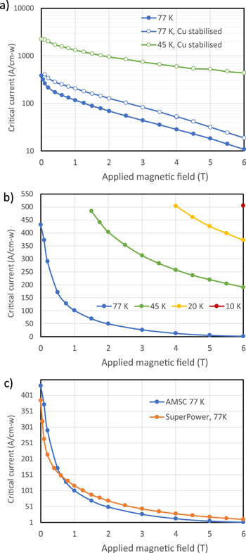
Two samples were tested. Firstly, a piece of SuperPower SF12030-AP tape with a rated Ic of 375 A/cm-w (figure B1(a)). Although this Ic is lower than that of the tape used in the stack (450 A/cm-w), they have the same production process and artificial pinning landscape and so the critical current data informs the scaling behaviour of Ic with flux density. Secondly, a piece of AMSC tape (figure B1(b)), which came from the same reel as that used for the hybrid stack and so is expected to be a close representation of the stack tape. Measurements of unstabilised 30 micron substrate tape are very difficult to achieve due to the lack of metallic material on both sides of the HTS layer. This leads to thermal runaway close to Ic and sample destruction. It was not possible to get any meaningful Ic data below 77 K for the unstabilised SuperPower tape. To get some indication of low temperature behaviour, a similar copper stabilized version was tested at 45 K. The data shows this sample has higher performance by comparison at 77 K, but the 45 K Ic(B) behaviour is still informative for the in-field shape of the curve. A comparison of the 77 K data for both samples is shown in figure B1(c). It should not be inferred that the SuperPower tape used in the stack has a lower Ic than the AMSC tape in self field, as the sample tested has approximately 83% of the Ic of the tape used in the stack. The purpose of this graph is to show that even for a similarly manufactured SuperPower sample which has lower performance at zero field, the in-field performance is much higher than the AMSC tape, largely due to the more complex artificial pinning landscape. In particular, the Ic is 64% higher at 3 T. Previous critical current studies on SuperPower tape show that Ic at 77 K and 3 T, is a key metric in determining lower temperature in-field critical current [22]. The Ic data serve as a useful reference and make it easier for other researchers to reproduce the sample and trapped field achieved.
Figure B1. Critical current data (Amps per centimeter width) for a similar but lower performance sample of the (a) SuperPower and (b) AMSC tape used in the hybrid stack of HTS tapes and a comparison (c) of the 77 K performance of both.
Download figure:
Standard image High-resolution image