Abstract
By simulating the passage of heavy ions along open channels in a model crystalline metal using semi-classical Ehrenfest dynamics we directly investigate the nature of non-adiabatic electronic effects. Our time-dependent tight-binding approach incorporates both an explicit quantum mechanical electronic system and an explicit representation of a set of classical ions. The coupled evolution of the ions and electrons allows us to explore phenomena that lie beyond the approximations made in classical molecular dynamics simulations and in theories of electronic stopping.
We report a velocity-dependent charge-localization phenomenon not predicted by previous theoretical treatments of channelling. This charge localization can be attributed to the excitation of electrons into defect states highly localized on the channelling ion. These modes of excitation only become active when the frequency at which the channelling ion moves from interstitial point to equivalent interstitial point matches the frequency corresponding to excitations from the Fermi level into the localized states. Examining the stopping force exerted on the channelling ion by the electronic system, we find broad agreement with theories of slow ion stopping (a stopping force proportional to velocity) for a low velocity channelling ion (up to about 0.5 nm fs−1 from our calculations), and a reduction in stopping power attributable to the charge localization effect at higher velocities. By exploiting the simplicity of our electronic structure model we are able to illuminate the physics behind the excitation processes that we observe and present an intuitive picture of electronic stopping from a real-space, chemical perspective.
Export citation and abstract BibTeX RIS

Content from this work may be used under the terms of the Creative Commons Attribution 3.0 licence. Any further distribution of this work must maintain attribution to the author(s) and the title of the work, journal citation and DOI.
1. Introduction
Along high symmetry directions in a crystal lattice, a fast moving ion can travel large distances in a process known as channelling. Such processes play an important role in ion implantation and in determining the damage distribution caused by high energy irradiation of metals [1]. Because very little momentum is transferred to surrounding atoms in their fleeting interactions with the fast moving ion, the predominant mode of energy loss from a channelling ion is electronic. Conventional molecular dynamics (MD) simulations use a conservative force field, so the potential energy depends only on the ionic positions and not on how or how fast the ions reached those positions. The conservative ionic potential may be viewed as an approximation to the Born–Oppenheimer potential surface used in quantum molecular dynamics, but neither conventional classical MD nor Born–Oppenheimer quantum MD is able to model the irreversible loss of energy from fast-moving ions to electrons. To introduce electronic losses, it is necessary to add non-conservative friction-like forces.
Various schemes have been proposed in order to account for electronic energy losses in classical MD [2–7] with varying degrees of success [8]. All such schemes make use of a damping force on moving ions (an electronic stopping power) proportional to their velocity and directly opposed to it: that is, they augment the equation of motion of ion i of mass mi to read,

where Fi is the force due to the interionic potential on ion i at position Ri. βi is the damping coefficient, most often chosen to be a constant β [5, 6], but sometimes given as a function of local electron density [2]. ηi represents any other forces added to the damping model, such as a stochastic force to represent return of energy from the electrons to the ions [2, 3].
The choice of a constant coefficient of damping, leading to a force proportional to the ion speed, is justified by appeal to Lindhard's stopping power theory [9, 10]. This considers the perturbation due to a charged particle intruding into a free electron gas and calculates the Coulombic force due to the cloud of screening electrons. When the particle moves at high speed, the screening cloud is unable to 'keep up' with the particle, giving rise to a retarding force, the strength of which will depend on the extent of the lag and on the effective charge of the particle. Within the approximations of linear response and free-electrons, the magnitude of the retarding force is found to be proportional to the speed of the ion at velocities well below the Bohr velocity.
Stopping power theories of the kind proposed by Lindhard treat the electron gas as translationally invariant. The atomic structure of the system is included only through the band structure used to construct the dielectric function. Consequently, no account is taken of the change to the electronic structure of the target due to the channelling ion. Several groups have calculated the variation of the electronic stopping power as a function of the position of a straight channelling path relative to the channel walls using a linear combination of atomic orbitals approach [12] and linear response [13], but these calculations do not account for the non-linearity in the response of the system required for the formation of a steady state. Non-linear calculations of slow ion stopping have been performed using density functional theory (DFT) [14], but they consider only a free electron gas as a target. All earlier theories of stopping power based on a free electron gas have omitted the atomic structure of the metal which gives rise to the resonance effects we report here.
An obvious improvement on augmenting a classical MD simulation with an externally imposed force derived from a continuum treatment of the electronic system would be to directly simulate the evolution of a system which includes the electrons explicitly and treats them quantum mechanically. Various such so-called semi-classical (or quantum–classical) simulation techniques are well established in the literature [15], but the computational challenges involved in simulating ion channelling are considerable. Not only must the usual convergence issues associated with static electronic structure calculations be addressed, but additional finite-size effects associated with the density of available transitions and peculiar to time-dependent calculations must be taken into account [16]. Our simulations must also allow time for a steady state to emerge. This can take several femtoseconds, during which the channelling ion can traverse many unit cells. The system sizes required to cope with these complications are at present inaccessible to the most accurate semi-classical approaches: time-dependent density functional theory calculations (TDDFT), for example, are restricted to systems of only a few hundred atoms.
TDDFT has recently been used to simulate the channelling of fast protons in Al [17, 18] and Au [19]. In these simulations the channelling particle is dragged along a fixed trajectory, rather than responding dynamically to forces from the surrounding atoms. Where forces are calculated for retrospective analysis purposes [17], they are those of Ehrenfest dynamics. As noted in [18] the results in [17] confirm our earlier findings [20, 21] that the principal effect of electronic excitations is to reduce the strength of bonding forces between ions.
By using Ehrenfest dynamics to simulate channelling processes in a time-dependent tight-binding (TDTB) [22] model of a metal, we can explore the role played by electrons in channelling processes via direct simulation. By adopting a particularly simple semi-empirical tight-binding (SETB) model [23] we achieve a treatment of the quantum mechanical electrons sufficiently efficient to reach the time- and length-scales necessary for convergence. We have recently reported the results of such simulations [24]. In the present paper we present new results which explore the effect of the strength of electron–electron interactions on the charge and stopping power of a channelling ion. These results elucidate the nature of the excitations responsible for the charging and stopping processes and inform an intuitive picture of the stopping power from a real-space, many-atom perspective. We describe our model and approach to channelling simulations in detail in section 2.
In section 3 we analyse the charge on the channelling ion as a function of its velocity and observe a resonant charging phenomenon in the valence electron states, analogous to the well-known resonant excitation of core electron states but at much lower channelling velocities. Over a well-defined range of velocities below the Bohr velocity, v0 = c/137, the steady-state negative charge on the channelling ion becomes significantly enhanced. We attribute this effect to the presence in the electronic structure of defect states highly localized on the channelling ion. When the frequency with which the channelling ion passes from interstitial point to equivalent interstitial point down the channel matches that associated with an excitation from delocalized bulk states below the Fermi level into the localized defect states, the enhancement in charge is observed. This charge localization effect is thus dependent both on the discrete periodic nature of the atomic lattice and on the presence of localized defect states in the electronic subsystem—it can emerge only when the atomic structure of the host lattice and the quantum character of the electrons are treated explicitly.
The charging effect that we describe can be compared with experimental results from 30 years ago. Datz et al [25] discovered what they termed a resonant coherent excitation (RCE) of swift hydrogen and helium like ions in crystals of Au and Ag. At velocities such that the channelling frequency matched the energies of excitation between core states of the channelling ion, resonances in the probabilities of various charge changing processes were observed (this is the Okorokov effect [26]). In contrast to the results presented here, the excitations detected by Datz et al do not change the charge on the channelling ion, but are excitations between states fully bound to the ion: the high sensitivity of the probability of other, charge changing, processes to the precise electronic state of the projectile is merely used as a means of detecting the core excitations. Furthermore, these core excitations occur at channelling velocities ≳5v0, much higher than those that we explore. A thorough theoretical treatment of the RCE phenomenon is given by Salin et al [27].
In section 3.1 we show that a simple analytical treatment of an oscillating interstitial atom using first-order time-dependent perturbation theory is sufficient to account for the details of the observed charge localization phenomenon in our simulations of channelling.
Our simulations also allow us to calculate the stopping power of the crystal lattice for the channelling ion and in section 4 we discuss the results. At lower velocities we find good qualitative agreement with the predictions of Lindhard's dielectric theory of electronic stopping [9, 10]. At higher velocities we see a reduction in stopping power above the velocity associated with the resonant charging phenomenon. We attribute this effect to the suppression of the bond orders between the channelling ion and the surrounding lattice, which results from excitations into the high energy defect state. The inclusion of charge-density-dependent terms in the Hamiltonian enhances this effect because the onsite Coulomb energy causes a mixing of the localized states and a reduction of the bonding interactions of the channelling ion.
Section 6 discusses the applicability of our results to real metals and section 7 considers the implications of our results.
2. Semi-classical simulations of channelling
To simulate the evolution of Nn classical ions and Ne quantum mechanical electrons we have adopted the approach of Ehrenfest dynamics [15]. The ions are treated as point particles, with position vectors R(t) = {R1(t),R2(t),...,RNn(t)}, whilst the electronic system is represented by a single-particle density matrix  . The density matrix evolves according to the quantum Liouville equation,

equivalent to the time-dependent Schrödinger equation, where  is the electronic Hamiltonian, dependent implicitly on time through its parametrization in terms of the ionic coordinates. The ions in turn evolve according to Newton's laws under a pairwise repulsive force and Hellmann–Feynman forces due to the electronic system,

where Vion is a repulsive potential that can be regarded as incorporating the Coulombic ion–ion repulsion and the double-counting corrections to the Hartree and exchange–correlation energies [28, 29]. For simplicity, we assume that the ionic masses M are all the same, but in principle our approach can be applied to any system for which an appropriate tight-binding model can be parametrized. Equations (2) and (3) represent our Ehrenfest dynamics. We have previously shown [30] that the mean field force on the ions due to the electronic subsystem is able to correctly reproduce the electron–ion energy transfer in circumstances when the flow of energy is predominantly from hot ions to cooler electrons. This is the case in ion channelling and so the well-documented failure of Ehrenfest dynamics to reproduce spontaneous phonon emission [31, 32] will not adversely affect our results.
In order to simulate systems sufficiently large and for sufficiently long times to treat ion channelling, we have adopted a particularly simple tight-binding model. This model [23] uses an orthogonal basis of s-like orbitals {|αi〉} with a single orbital centred on each ion. This is the simplest possible model that captures the essential physics of the problem. Electrons are treated explicitly, quantum mechanically and self-consistently, the discrete atomic structure of the metal is treated explicitly, and most importantly the system size is sufficiently large for a steady state to be established. When the s-band is nearly empty or nearly full the dispersion relation becomes that of a free electron gas but still with discrete atoms. The model has all the physics of the earlier jellium treatments of channelling but with discrete atoms. The hopping integrals between orbitals in the perfect crystal are then given by simple inverse power law functions γ(r) of the interionic separation [23] to give a Hamiltonian,

where γ(r) ≤ 0. The hopping integrals and the repulsive ion–ion interaction are parametrized to reproduce selected elastic and structural properties of face-centred cubic (fcc) copper and a metallic electronic structure. The model is not claimed to be an accurate representation of the electronic structure of copper: rather it provides a model metallic material with which we can explore the physics of electronic excitations in ion channelling involving many thousands of metallic atoms. To account for the energy associated with charge transfer, the Hamiltonian is augmented to give a total energy expression,


corresponding to additional onsite elements in the full Hamiltonian, and becomes,
qi is the excess number of electrons on the ith ion, given by,

where ν is the band-filling, related to the number of electrons in the system by Ne = 2νNn. In our model ν is a fitted parameter. For |Ri − Rj| > 2a where a = 3.61 Å is the unit cell width, zij is tapered smoothly to zero at half the simulation cell width to avoid spurious interactions between charged ions and their replicas in a periodic simulation cell. The parameter U (a Hubbard parameter) describes an energy penalty for accumulation of electronic charge on a single ion and V describes the Coulomb interaction energy between charged ions. More details of the model and its use in time-dependent tight-binding simulations can be found in [8, 16, 20, 33–36].
Our simulations take place in a simulation cell of 7×9×32 fcc unit cells (8064 atoms) of our tight-binding copper, with periodic boundary conditions in all three dimensions and with the atoms held fixed at their perfect crystal lattice sites. We then introduce an additional copper ion, our channelling ion, at a tetrahedral interstitial site6. This channelling ion will be periodically repeated across the cell boundaries, but the whole cell remains electrically neutral and efficient metallic screening means that the interaction of the charged projectile with its images will be insignificant. The electronic system is initialized at a temperature of Te = 1000 K (employed in order to improve convergence of the self-consistent ground state) such that the initial density matrix is,

where {|ϕi〉} are the eigenstates of the initial Hamiltonian  and {εi} their eigenvalues. f(ε;Te,μ) is the Fermi–Dirac distribution with chemical potential μ chosen to give the correct number of electrons (∑if(εi;Te,μ) = νNn). We have found that lateral dimensions for the simulation of 7 unit cells achieve convergence of the Hartree energy. The initial eigenstates are solved self-consistently by first solving for the perfect crystal, then introducing the self-interstitial by adiabatically switching on the interaction with its neighbours over 20 fs.
At time t = t0, the channelling ion is given an initial kinetic energy between 1 keV and 1.4 MeV along the long axis of the simulation cell. The other ions in the simulation are held fixed, not to make the simulation more efficient (the computational cost associated with allowing all the ions to move is small relative to that involved in calculating the commutator in (2)), but to allow the non-adiabatic energy transfer into the electronic system to be calculated without having to repeatedly find the instantaneous self-consistent ground state. By fixing the surrounding lattice the ionic positions and the electronic ground state are made strictly periodic in time and the energy transferred irreversibly into the electronic system, which we denote ΔE(t), and corresponding to the electronic stopping power, will be equal to the loss in kinetic energy of the channelling ion between equivalent points along its path. The low impulse imparted to the surrounding ions by the passing projectile makes the fixed lattice approximation physically reasonable.
In addition to ΔE(t), we also monitor the charge on the channelling ion. As an unrelaxed tetrahedral interstitial the initially static ion has a significant negative charge. The shorter than average bonds to its nearest neighbours create low energy bonding states in which electrons accumulate (our band is less than half full, ν < 0.5). Once the projectile is set in motion it takes some time for a dynamic steady state charge to be achieved. The charge continues to oscillate with the changing atomic environment along the ion's path, but it does so around a mean value that depends on the ion's velocity. We have found that a steady state is achieved after 4–6 fs, which is consistent with charge equilibration seen experimentally after 7 fs even for initially highly charged ions [37]. It is this charge equilibration time that dictates the long dimension of our simulation cell, which needs to be at least 120 Å long for the highest speeds that we investigate. The requirement that the channelling ion achieves its steady state before crossing the periodic cell is not an obvious one. The projectile will experience the effects of the periodic boundaries as soon as any disturbance to the electronic system has had time to wrap around the cell. At the velocities we study, the time for this self-interference, being dependent on the higher electron velocity, is shorter than the time for the projectile to cross the cell and so sets a harsher limit. However, we have found our results to be unaffected by such effects, whereas we see significant perturbation of the steady state when the channelling ion retraces its path. We attribute this latter effect to slowly decaying localized disturbances in the wake of the channelling ion.
To obtain the results discussed in the following sections 3 and 4, we have implemented a spline fit to the simulation output so that we can compare charges and energies at precisely translationally equivalent points along the ion path. Mean values and gradients of the variables are then calculated using least-squares fitting. Sample data are illustrated in figure 1.
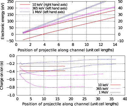
Figure 1. An example of the position dependent data for electronic energy (top panel) and ion charge (bottom panel). The data are spline-fitted to extract upper and lower bounds for the variation of the values and plotted from the first unit cell onwards. As the oscillations show only a single frequency, an average can be found from the midpoint of the upper and lower bounds, which may be used to construct derived quantities such as the gradient.
Download figure:
Standard imageFigure 2 illustrates the charge distribution in the steady state at a sample of different ion velocities. At low velocities (e.g. 10 keV, 0.16 keV/amu, 0.17 nm fs−1) the charge distribution differs little from the static case. The negatively charged channelling ion is surrounded by compensating positively charged ions and charge oscillations at large distances are visible. At 365 eV (5.7 keV/amu, 1.05 nm fs−1) the distribution of screening charge is no longer spherically symmetric about the channelling ion. The finite response time of the electrons to changes in the Hamiltonian is manifest as a failure of the screening cloud to keep pace with the projectile. At higher velocities still (1 MeV, 15.7 keV/amu, 1.74 nm fs−1) new effects are seen. A 'streak' of negative charge is visible behind the channelling ion as localized bonding states are left behind by the projectile and disperse slowly.
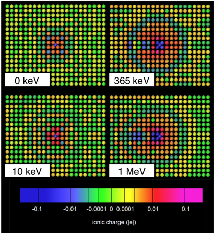
Figure 2. Snapshots of the ionic charge distribution in the steady state for channelling ions at a sample of kinetic energies. The channelling ion is at the centre of each plot and is moving from left to right. The various features of the plots are discussed in the main text.
Download figure:
Standard image3. The charge on a channelling ion
Figure 3 shows the steady state average charge as a function of ion velocity for a variety of choices for the parameters for charge density dependence, U and V, around the physically realistic values of U = V = 7 eV. At low velocities the average charge is as for the quasistatic case. The effect of the Hubbard U parameter is clearly visible in this limit, with higher values suppressing the piling up of charge on the channelling ion.
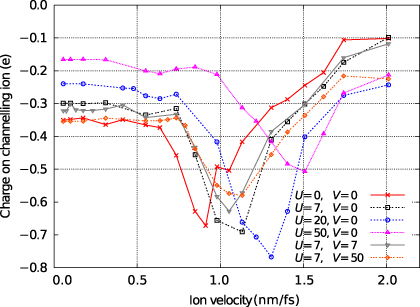
Figure 3. The steady state average charge on the channelling ion as a function of its velocity. Data for various choices for the parameters for charge density dependence, U and V (given in eV), are shown and are discussed in the main text.
Download figure:
Standard imageThe most striking feature of figure 3 is the significant increase in the negative charge of the projectile at velocities between 0.5 and 1.5 nm fs−1. This feature is unexpected, but we can understand its origins if we examine the local density of states (LDoS) on the channelling ion. In figure 4 we see that the LDoS is dominated by a group of low energy states corresponding to strong bonding interactions between the interstitial atom and its abnormally close neighbours and by a high energy state some distance above the top of the tight-binding band. In section 6 we will show that these features of the LDoS are physically reasonable and are reproduced in DFT calculations for equivalent systems. At the beginning of the simulation, this local density of states will be occupied up to the Fermi level. As the ion moves down the channel, the rate at which it passes from one interstitial point to the next, a distance of d = a/2 = 1.805 Å, will define a dominant frequency within its motion,

where v is the ion velocity. The moving ion will stimulate excitations in the electronic system at energies ħω corresponding to this frequency. If the velocity is high enough, then excitations from occupied states below the Fermi level into the unoccupied high energy state, indicated schematically and marked (A) in figure 4, will become possible. Such excitations are from delocalized states into a state highly localized on the channelling ion and so will give rise to the observed charge accumulation. At higher velocities still, the projectile will excite electrons from the localized bonding resonances at the bottom of the band into unoccupied delocalized states above the Fermi level. Transitions of this type, indicated and marked (B) in figure 4, will counteract the charge localization and are responsible for the decay in the charge response at higher velocities.

Figure 4. The density of states for our model metal (dashed (blue) line) and the local density of states on the channelling ion (solid (red) line). In the latter, highly localized defect states are apparent at the bottom of the band and above the top of the band. The initially occupied states are shown shaded (green) and the Fermi level is at −2.83 eV. At the bottom of the figure, two types of transition are indicated schematically. Transitions of type (A), from occupied bulk states into the defect state, will localize charge on the channelling ion. Those of type (B) will delocalize charge. The full DoS encompasses two electrons per ion in our system, the LDoS the two electrons on the channelling ion.
Download figure:
Standard image3.1. Perturbation theory analysis of the charge response
Before we go on to discuss the behaviour of the charge with changes to the parameters for charge density dependence and the channelling direction, we can obtain support for our explanation of the charge accumulation phenomenon from a simple time-dependent perturbation theory analysis. Instead of treating the case of a channelling ion we will consider a single unrelaxed tetrahedral interstitial, within an otherwise perfect crystal, forced to undergo sinusoidal oscillation in the 〈100〉 direction at angular frequency ω. Time-dependent perturbation theory gives us a Fermi's Golden Rule (FGR) expression for the excess charge on the channelling ion Δqa,
 is the perturbation—the change in the Hamiltonian
  due to moving the interstitial atom away from its tetrahedral position—and s(i,j;ω,t) is the usual FGR time dependence for a sinusoidal perturbation,
The δ-function terms correspond to transitions of ħω upward and downward in energy. In writing equation (11) we have omitted the purely oscillatory effect of the off-diagonal terms in the density matrix in the energy eigenstate basis. These off-diagonal terms have zero contribution to the more common FGR expression for the energy transfer [16].
The results of a perturbation theory calculation (on a 3600 + 1 atom system) using equation (11) are shown in figure 5 along with data for non-self-consistent channelling simulations (U = V = 0) in which the correspondence between frequency and channelling velocity is made using equation (10). The onset and shape of the charge accumulation feature exhibit a pleasing agreement. The effects of the two types of charge changing processes (marked (A) and (B) in figure 4) are shown separately and confirm our explanation of the shape of the charge feature. At energies above 25 eV the agreement is less good, because at high velocities an oscillating interstitial becomes an increasingly poor analogue of the ballistic channelling ion.

Figure 5. Results of a simple FGR calculation (solid (red) line) of the charge on an oscillating interstitial atom (described in the main text) compared to the steady-state charge found in a non-self-consistent channelling simulation (U = V = 0) (black circles). The energy is given by ħω where ω is either the angular frequency (for the oscillator) or is given by (10) (for the channelling ion). The onset and width of the charge enhancement feature are correctly reproduced. The (blue) short dashed and the (purple) dotted line show the contributions from the two types of transitions (A and B respectively) illustrated in figure 4. The vertical scale is arbitrary as the FGR result is simply proportional to time.
Download figure:
Standard imageIn figure 5 the relative scale of the simulation and perturbation theory results is chosen arbitrarily. This is because the FGR treatment (11) does not predict a steady state, being in any case valid only for a low degree of excitation. In our channelling simulations the scale of the variation of the hopping integrals between the projectile ion and its nearest neighbours lies far outside the perturbative regime. Excitations occur at a high rate and a steady state is established fairly rapidly. At the charge resonance this steady state will occur when the occupations are such that there is a balance between transitions up and down in energy between the high energy defect states and the states lying hv/d below them.
3.2. The effect of the parameters U and V
Returning to our discussion of the simulation results in figure 3, we will consider the effect of varying the parameters for charge density dependence, U and V. First, the difference between a non-self-consistent simulation (U = V = 0) and one with physically reasonable values of U = V = 7 eV is small. Only by further increasing the values of U and V can we effect large changes. By exploring such a wide range of values for U and V we are not aiming to predict the behaviour of real materials, rather we are exploiting the simplicity of our model to deepen our understanding of the physics behind the phenomena that we have observed. As previously remarked, increasing U penalizes the accumulation of onsite charge and so reduces the quasistatic charge seen at low velocities. The charge accumulation effect is shifted to higher velocities as U is increased. The presence of charge-density-dependent terms in the full Hamiltonian  means that as electrons are excited into the high energy defect state the energy of that state will increase. The velocity required for further excitation must increase to match the larger gap between the Fermi level and the defect state and so the velocity of the maximum charge response will shift upward (see figure 6).

Figure 6. A schematic view of the change in the position of the high energy defect state as it becomes occupied in the case where U > 0. The diagrams show the local density of states with occupied states shown shaded. The separation of the defect state from the Fermi level is increased for higher U, increasing the velocity at which the maximum charge response occurs.
Download figure:
Standard imageA further effect of increasing U is to increase the negative charge enhancement between the quasistatic case and the maximum charge response. This occurs because there is a periodic fluctuation in the occupation of the high energy state as the local atomic environment of the channelling ion varies. For high U, this changing occupation implies an increase in the magnitude of the oscillation of the energy of the defect state. In turn, this means that it is accessible to electrons excited from a broader range of occupied states below the Fermi level and that the steady state (essentially a point of balance between excitations into and out of the defect state) is established with a higher occupation of the defect state (see figure 7).
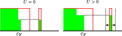
Figure 7. A schematic view of the states contributing electrons to the high energy defect state in the steady state. For U > 0, fluctuation in the energy of the defect state with its occupation means that excitations from a broader range of states below the Fermi level are possible.
Download figure:
Standard imageChanging V does not have such a dramatic effect. The position of the charge feature is not shifted, but the magnitude of the charge enhancement is reduced with increasing V. This behaviour can be explained if we note that the energy of the localized high energy defect state will vary with the position of the channelling ion. Its energy will be highest when the channelling ion passes between two neighbouring close-packed atoms and the hopping integrals are at their most negative. Its energy will be lowest when the ion is at a tetrahedral interstitial point. This fluctuation in the energy of the defect state means that occupied bulk states across a range of energies below the Fermi level will contribute to the charge localization. When V is non-zero, an excess charge on the projectile will give rise to a positive contribution to the electronic energy, dependent on the bond lengths, reducing the range over which the energy of the defect state will vary. Fewer occupied bulk states will contribute to charge localizing excitations and the steady state will occur at a lower occupation of the defect state (this is the opposite of the effect of increasing U, described above and illustrated in figure 7).
4. The electronic stopping force on a channelling ion
Figure 8 shows the stopping powers experienced by the channelling ion in the steady state in each of our simulations. These stopping powers are calculated as averages from the loss of kinetic energy as the projectile moves between equivalent positions along its path. At velocities of up to 0.5 nm fs−1 the channelling ion experiences a stopping force that is broadly proportional to its velocity:
This is in agreement with stopping theories of slow ions such as those of Lindhard [9, 10] and Fermi and Teller [11]. Assuming that the stopping force can be modelled using a constant damping coefficient we can calculate an effective value for β in equation (13). We find, by least-squares fitting, a value of β = 0.44 ± 0.01 eV fs Å−2. This can be compared with a value of β = 0.636 ± 0.004 eV fs Å−2 that we calculated previously [8] for moving ions in small, low energy cascades simulated using our model. The difference in the values is due to the different range of electronic and atomic environments experienced by the moving ions in each case.

Figure 8. The effective electronic stopping power as a function of projectile velocity in the steady state of our channelling simulations. U and V are given in electronvolt. (See main text for discussion.)
Download figure:
Standard imageIn all cases, at higher velocities the stopping power falls below the constant damping line. Where we have a large value of the U parameter, a significant depression in the stopping power appears over the same range of velocities as the charge enhancement feature in figure 3. To understand this feature we must note that within our tight-binding model it is an asymmetry in the bonding around the channelling ion that gives rise to the electronic stopping power (see figure 9). This is a non-adiabatic effect, due to the finite response time of the electrons to changes in the ionic positions and is analogous to the lag in the screening response in Lindhard's dielectric theory. The excitation of electrons into the localized defect state significantly reduces the strength of the bonding interactions because of the anti-bonding character of this state. The stopping power is thus also reduced.
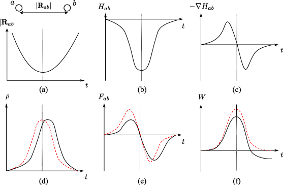
Figure 9. A schematic illustration of the mechanism of stopping in a local bonding picture. The panels show the evolution of the various bonding parameters, with the point of closest approach indicated by a dotted line. The solid lines indicate the time-dependent response, the (red) dashed lines the ground state response. (a) The evolving separation between a pair of ions. (b) As the atoms approach one another, the hopping integral of the bond becomes increasingly negative. (c) The spatial derivative of the hopping integral, on which the Hellmann–Feynman force depends. (d) The density matrix element between the atoms increases as they approach. In the adiabatic case this bond between the colliding atoms forms and breaks symmetrically about the point of closest approach, but the finite electronic response time introduces a lag in the time-dependent response. (e) The asymmetry in  introduces an asymmetry in the force between the ions, which (f) leads to a net work on the channelling ion, corresponding to the stopping power.
Download figure:
Standard imageWe can see the effect of populating the defect state in figure 10. We plot the magnitude of the periodic variation ΔE in the bond energy  as a function of the channelling ion velocity. This energy will track the variation of the hopping integrals between the projectile and its neighbours, becoming most negative as the ion passes between close-packed neighbours, but will also depend on the bond orders within the density matrix. A steep drop-off in the size of the variation occurs when the anti-bonding defect state becomes populated.
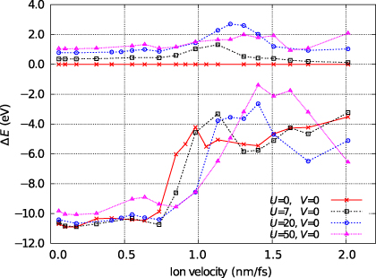
Figure 10. The magnitude of the periodic variation as a function of ion velocity in the two contributions to the electronic energy. The lower set of lines (values <0) shows the variation in the bond energy  , defined as the difference between the minimum and maximum values of
  recorded as the channelling ion passes a nearest neighbour. The upper set (values >0) show the variation in the difference between the maximum and minimum values of the Coulomb correlation energy
  . Both sets of lines show features at the same velocity as the charge feature in figure 3. U and V are given in electronvolt.
Download figure:
Standard imageThe effect of U ≠ 0 is also indicated in figure 10 as the magnitude of the periodic variation in the Coulomb correlation energy  . This variation acts in step with the variation in the bond energy, but with the opposite sign. Essentially, what is revealed is a further U-dependent suppression of the bond orders to the channelling ion when the high energy defect state becomes highly occupied. Occupation of this state localizes electrons on the channelling ion and so increases its negative charge. At finite U this gives rise to an onsite perturbation to the electronic Hamiltonian, which acts to 'mix' together the low and high energy defect states. As a result, the bonding character of the fully occupied low energy defect states is reduced, suppressing the bond orders. This effect will clearly be stronger at higher values of U.
There is an important difference between the variation of the ion charge with channelling velocity (figure 3) and the variation of the stopping power. The charge feature has a finite width because at higher velocities excitations out of the low energy bonding states act to delocalize charge and cancel out the effect of charge localizing excitations into the high energy defect state. The behaviour of the reduction in the stopping power is more complex. That part of the reduction due to changes in the bond order due directly to excitations (revealed in the scale of fluctuations in the bond energy for U = 0 in figure 10) persists at higher velocities because the excitations out of the low energy bonding states have the same effect as excitations into the high energy state, i.e. they both act to reduce the bond order. The part of the reduction due to charge density dependence, however, shows a well-defined width because the extent of the bonding character of the low energy defect state is directly related to the charge on the channelling ion. The total effect on the stopping power is the sum of the persistent reduction and an enhanced U-dependent reduction of finite width.
4.1. Contribution of plasmons
At sufficiently high velocities, the channelling ion should be able to excite plasmons. However, the low sensitivity of the stopping power to the inter-site Coulombic interaction parameter V suggests that plasmons make at most a small contribution to the energy loss in our simulations. In our single orbital tight-binding model we can calculate the plasma frequency,
where vF and kF are the Fermi velocity and Fermi wavevector respectively. To derive (14), the usual expression for the electrical susceptibility in terms of single-particle eigenstates is used [38]. From this the frequency at which the dielectric function goes to zero in the limit q → 0 is found. In addition to considering only a single band, it is assumed the Fermi surface is spherical so a unique kF can be defined. We find ħωP = 13.68 eV, an energy corresponding to a channelling velocity of ωPd/2π = 0.596 nm fs−1. In figure 11 we plot the contribution to the stopping power of the charge-density-dependent terms, i.e. −dESC/dx where,
and x is the distance along the projectile's path.

Figure 11. The stopping power due to energy accumulating in the charge-density-dependent terms in the total energy expression (5). This is non-zero over only a small range of velocities above the plasma frequency and never contributes more than a few tenths of a per cent of the total electronic stopping power (the right hand axis shows the percentage of the maximum total electronic stopping power). U and V are given in electronvolt.
Download figure:
Standard imageSome small amount of energy is lost into the Coulomb correlation energy just above the velocity ωPd/2π giving a contribution to the stopping power that is ∼0.2% of the total. The finite width of the plasma response and its deviation from the expected frequency are likely due to our finite electronic temperature and plasmon wavelength. The fact that we see a distinct contribution to the energy loss at the ion velocity corresponding to the plasmon frequency for our model indicates that the simulation is capturing the plasmon loss at least to some extent. However, given the approximations in the electrostatics embodied in equations (5) and (6), it is possible that we are not capturing all of it. Nevertheless it is clear that the model is able to disambiguate bonding and plasmon losses, which is our principal concern here. At the low velocities that we explore, significantly below the Fermi velocity, only small losses to plasmons are expected [39].
5. The effect of channelling direction
In figure 12 we show the results of channelling simulations with U = V = 0 for an ion moving down a channel in the [110] direction. We compare the steady-state charge and stopping power as a function of velocity with the equivalent simulations for the [100] channel. Given our explanation for the behaviour of the results in the [100] channel we expect to see the charge response in the [110] channel at velocities a factor of  higher, since the periodic repeat distance of the atomic environment of the projectile is
  in the latter case, compared to d/2 in the former. Lines are marked in figure 12 at two velocities differing by this factor of
  to aid in reading the plots and suggest that the behaviour is as expected. The geometry of the [110] channel is such that the variation in the nearest neighbour hopping integrals to the channelling ion is larger and so we should expect to see a less well-defined resonance. This too is confirmed by the data in figure 12.
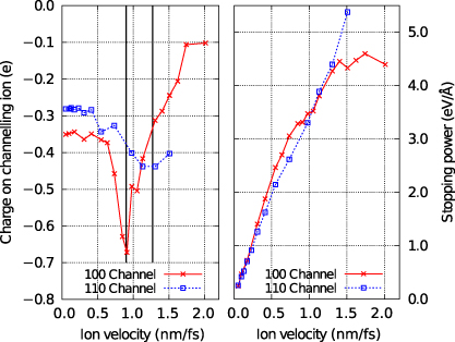
Figure 12. The steady-state charge (left panel) and stopping power (right panel) for two different channels. In the left hand panel the two vertical lines are marked at velocities that differ by a factor of  equal to the ratio of the periodic repeat distances along the two channels.
Download figure:
Standard image6. Resonant charging in real metals
The results discussed above were obtained with a very simple model of a metallic electronic structure. We chose such a model out of necessity, to allow us to simulate the required time- and length-scales, but it brings the added advantage that we can more easily explain the physical mechanisms at work. The phenomena we observe arise due to the periodicity in the atomic environment of the channelling ion and the action of the time-dependent Schrödinger equation; they are not a quantitative feature of some particular detailed electronic structure.
However, to understand how our results might apply to real metals, we have carried out DFT calculations of an unrelaxed self-interstitial ion in copper using the VASP code [40]. The calculations were made using the PAW (projector augmented wave) method [41] and were converged for a 108 + 1 atom cell, an 8×8×8 Monkhorst–Pack grid with 1600 bands and a 900 eV kinetic energy cut-off. We found it necessary to include 3p electrons in addition to the 3d and 4s. Though the 3p states are well separated in energy, they have a significant spatial overlap and give rise to additional resonances near the Fermi level. An important feature of these DFT calculations is the much larger basis set that results in states being available at much higher energies. This allows us to investigate the possibility that our tight-binding result is an artefact of the narrow band that our model produces; our DFT result shows it is not an artefact.
The local density of states (LDoS) on the interstitial ion is shown in figure 13 along with plots of the spatial charge density in selected energy ranges containing resonance features. The LDoS was calculated in a sphere of radius 1.12 Å, which would be space-filling for periodic repeat of the interstitial ion's local tetrahedral environment.
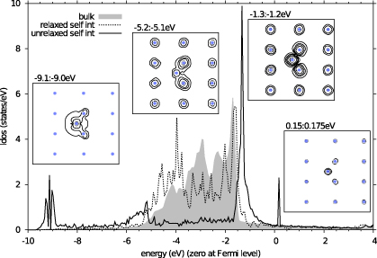
Figure 13. Densities of states (DoS) for copper calculated using DFT. The solid line shows the DoS for an unrelaxed tetrahedral self-interstitial. This can be compared with the DoS for a relaxed interstitial (dotted line) and the bulk density of states for perfect copper (shaded area). The local density of states for an unrelaxed tetrahedral interstitial clearly shows the existence of a sharp anti-bonding resonance above the Fermi level (set to zero) and bonding resonances at the bottom of the band. These resonances are not present when the atomic positions around the defect are relaxed. The bulk copper density of states is shown for comparison. Inset: charge density in a {110} plane containing the interstitial for a narrow range of energies centred on the resonances. Contours are on a log scale: the lower energy resonances at 10−3,10−2.5,10−2 etc Å−3, above the Fermi level at 10−3.25,10−3.0,10−2.75 Å−3.
Download figure:
Standard imageOur DFT calculations confirm our prediction of resonant states localized on the channelling ion. Thus the features which emerge in the LDoS of our simple model are also reproduced when the more accurate DFT approximation to the electronic structure of real materials is applied. We have found similar resonances in equivalent calculations for other metals and they appear to be a general feature. In metals in which such resonances lie above the Fermi level (as in our simple model), we would expect to see a resonant enhancement in the negative charge on a channelling ion. In metals where the resonances are below the Fermi level, and initially fully occupied, we should see a resonant reduction in the negative charge.
7. Conclusions
By combining quantum mechanical electrons and an explicit model of classical ions we obtain a model with the physical content necessary to explore non-adiabatic phenomena in ion channelling. Because we adopt a particularly simple tight-binding model we are able to directly simulate the channelling of slow heavy ions in a metallic crystal.
Our simulations reveal a previously unpredicted enhancement of the charge on the channelling ion at velocities well below the Bohr velocity. The onset of the charge enhancement occurs when the frequency with which the projectile traverses its periodic atomic environment matches the separation of the Fermi level and a high energy defect state localized on the channelling ion. The width of the enhancement depends on the frequency necessary to stimulate delocalizing transitions from localized bonding states to unoccupied bulk states above the Fermi level.
When we examine the electronic stopping power on the channelling ion we find a force proportional to velocity up to ≈0.5 nm fs−1 in agreement with stopping power theory [9, 10]. At higher velocities the stopping power falls below theoretical predictions as charge localization acts to reduce the bond orders whose asymmetry gives rise to the stopping force within the tight-binding picture. We find that both the charge response and the behaviour of the stopping power with velocity have a low sensitivity to realistic values of the parameters for charge density dependence U and V. Stronger variations at higher values of U and V are explained within the model and illuminate the physics behind the variations in the charge and stopping power. We find that whilst plasmons can be and are excited by the interaction of the channelling ion with its neighbours, they absorb little energy and contribute ≲0.2% of the total electronic stopping power at the low speeds explored in our simulations.
Because we have necessarily employed a simple model of the target system our results should not be treated as quantitative predictions of ion charge and stopping power. However, in channelling events in real metallic targets we would predict an analogous response of the channelling ion charge and corresponding variation in the stopping power. The magnitude of the response and the velocity at which it occurs will depend in detail on the electronic structure of the target. In particular, whether the charge shows an enhancement or a depletion will depend on the position of localized high energy defect states above or below the Fermi level respectively. Our own DFT calculations of the electronic structure of unrelaxed tetrahedral self-interstitial defects in a variety of metals suggest that such resonances are a general feature of self-interstitial defects and other interstitials of comparable or larger size.
Acknowledgments
Calculations were performed on Hector and IC-HPC. DRM and CPR were supported by EPSRC grant number EP/C524403. We would like to thank Tchavdar Todorov for his insights into the underlying physics of the results discussed here and Stefaan Cottenier for confirming our DFT calculations using a LAPW basis set.
Footnotes
- 6
Though we treat a self-ion here, our method could be used for any combination of host and channelling species for which a suitable tight-binding parametrization is available.