
Abstract
The ISOLDE facility has undergone numerous changes over the last 17 years driven by both the physics and technical community with a common goal to improve on beam variety, beam quality and safety. Improvements have been made in civil engineering and operational equipment while continuing developments aim to ensure operations following a potential increase in primary beam intensity and energy. This paper outlines the principal technical changes incurred at ISOLDE by building on a similar publication of the facility upgrades by Kugler (2000 Hyperfine Interact. 129 23–42). It also provides an insight into future perspectives through a brief summary issues addressed in the HIE-ISOLDE design study Catherall et al (2013 Nucl. Instrum. Methods Phys. Res. B 317 204–207).
Export citation and abstract BibTeX RIS

Content from this work may be used under the terms of the Creative Commons Attribution 3.0 licence. Any further distribution of this work must maintain attribution to the author(s) and the title of the work, journal citation and DOI.
1. Introduction
The production of radioactive ion beams via the isotope separation on-line (ISOL) technique is a well-established method for the production of radioactive ion beams (RIBs). At ISOLDE, spallation, fragmentation and fission reactions are produced in thick targets bombarded by a pulsed proton-beam with an energy of 1.4 GeV and an average intensity up to 2 μA. The reaction products are then extracted, ionized, accelerated and separated to provide a variety of RIBs for a comprehensive physics program. The ISOLDE facility has two mass separators; the general purpose separator (GPS) and the high resolution separator (HRS). The GPS magnet is an H-magnet type with a bending radius of 1.5 m and a bending angle of 70°. Its resolution m/Δm is approximately 800. The HRS has two magnets; a 90° magnet and a 60° magnet. Both are C-magnet types and both have a bending radius of 1 m. The overall resolution of both magnets has been measured at approximately 6000. The magnets of both separators have a window providing a direct view to the target ion source for laser ionization. While both separators feed the array of beam lines in the experimental hall, the GPS has two more beam lines simultaneously able to extract beams up to ±13% of the central beam line mass.
In order to maintain its status as a world-wide reference with regards to RIB production, the ISOLDE facility has maintained a continuous investment in its infrastructure. Other reasons for this investment are the inherent ageing of the facility and the adoption of new technologies beneficial to the production and manipulation of RIBs. Examples of regular maintenance of the facility has included the replacement of; the tape station, the ISOLDE target stations (Frontends) and the target handling robots. While the replacement of the two latter is justified by their deterioration in a harsh radioactive environment, the new radioactive beam sampling and detection device (tape station) replaces a similar system that is over forty years old. Their replacement however, has provided an ideal opportunity to improve on their performance by taking advantage of new technologies and by building on past experience.
The RFQ Cooler [3–6] is a new addition to the beam lines and was driven by requests for bunched secondary ion beams with a low emittance. It was decided to add this device to the exit of the HRS due to both space constraints and the ability to serve the majority of experiments throughout the hall. Upgrades are essential in maintaining overall performance to a high standard and over the last 17 years, upgrades have been applied to beam instrumentation, high voltage systems, the control system and the radiation monitoring system.
New activities and providing a safe working environment for the handling of radioactive material have required the addition of new buildings. In compliance with the Swiss classification criteria for radio toxicity, the Class A laboratories were commissioned in 2005 and consequently provided a conform environment for the handling of radioactive material at ISOLDE [7]. However, with the approval of the MEDICIS (medical isotopes collected at ISOLDE) project, it became clear that an extension of the Class A laboratories was required [8, 9]. This was implemented during the first long shutdown (LS1) period at CERN in 2013 to minimize the impact on operations at ISOLDE.
Figure 1 exemplifies the expansion of ISOLDE over the last 17 years in terms of civil engineering. It shows the extensions added to the target area entrance for the Class A and MEDICIS laboratories as well as the extension and infrastructure buildings for the HIE-ISOLDE project.

Figure 1. A 3D model of the ISOLDE Facility in 2017 showing the recent extensions.
Download figure:
Standard image High-resolution imageIn the foreground there is the addition of building 508 adjacent to the north wall of the experimental hall which came into service in 2015. The ground floor, as shown, is dedicated to the solid state physics laboratories while the second floor provides data acquisition rooms and control rooms for both ISOLDE and resonance ionization laser ion source operation. Once building 508 was in place, a controlled access system covering the experimental hall and the solid state physics laboratory was implemented thus providing a physical barrier defining the ISOLDE perimeter.
Finally, with a possible increase of energy and intensity of the proton-beam to ISOLDE due to the 2 GeV upgrade of the PS-Booster and the commissioning of Linac 4, investigations are already under way to better exploit and manage these new primary beam parameters [10–12]. This has been done within the HIE-ISOLDE design study and covers not only the energy and intensity upgrade but also improved secondary beam quality.
This paper provides an update of the ISOLDE Facility by building on the above-mentioned topics. It provides an approximate timeline of the various modifications of the facility while giving an insight into the justification of different choices.

Figure 2. A cross-section view of the ISOLDE Frontend showing 1. The X–Y deflector plates 2. The modified piston for target coupling and 3. The tripod support system.
Download figure:
Standard image High-resolution image2. Low energy ISOLDE
The term low energy ISOLDE refers to all the equipment used for the production of RIB up to an energy of 60 kV. This includes the target stations, the mass separators, beam manipulation devices and beam lines. This chapter covers the recent and planned modifications of the low energy part of ISOLDE.
2.1. The frontends
The expected lifetime of the ISOLDE target stations, more commonly known as Frontends, is typically seven years and with each Frontend change, modifications are made to enhance its reliability, minimize the need for maintenance and reduce the time required for interventions. In the more recent past, the Frontend has been modified to accommodate a new coupling table with an all-metal piston for target coupling to improve on the interface with the new robotic handling system. The last Frontend exchange took place in 2010 for the HRS and 2011 for the GPS and included the following modifications:
- −A more radiation resistant ceramic insulator to replace the previous polyether ether ketone insulator separating the 60 kV elements from those at ground potential
- −RF and controls connections to increase the potential of target variations
- −Cable patch panels for quick replacement of damaged cables
- −Electrostatic deflectors to replace the need of mechanical adjustment of the extraction electrode in the vertical and horizontal direction
- −A compressed air motor with programmable logic controller (PLC) controls and redundant micro-switches for extraction electrode displacement
- −A tripod support system with alignment references for remote alignment checks
- −A new cabling loom between the Frontends and the shielded high voltage platforms to replace the deteriorated cables
- −In the case of the HRS Frontend Faraday cage; this has been modified to integrate the new MEDICIS irradiation point while maintaining its role as a sealed Faraday cage unit. Figure 2 provides a cross-section view of the existing frontends at ISOLDE.
2.2. The radio frequency quadrupole cooler and buncher (RFQCB)
After mass separation, typical emittances of the ion beam are 10–40 π mm mrad. Beam losses are proportional to emittance which in turn penalizes experiments with a small acceptance. By bunching the radioactive ion beam, many decay measurement experiments benefit from an increase in the signal-to-noise ratio provided the space charge limit of the RFQCB is not exceeded. With these criteria in mind, the RFQCB was developed and installed at the exit of the HRS separator in 2008, as shown in figure 3. The ISCOOL (ISOLDE cooler), as it is more commonly known, is defined as a general purpose cooler and buncher of RIBs. The incoming ions lose their energy through collisions with a neutral buffer gas while the oscillating quadrupole field of the linear RF provides radial confinement. A combination of electrostatic elements provides an electric field gradient and allows the beam to be bunched before extraction. Operational parameters of the ISCOOL are given in table 1.
Typical transmission values from in front of the 60° magnet to the beam diagnostic box just after the ISCOOL are given in table 2. These measurements were done with an injection and extraction energy at 40 kV. It is important to note that transmission values are given for continuous mode operation (no specific pulse structure) and can vary as a function of isotopic mass, secondary beam emittance and beam energy.
In 2015, the technique of optical pumping was used in the RFQ Cooler for the first time to enable the quadrupole moments of neutron-rich odd–even ionic manganese isotopes to be measured [13]. During their entrapment in the RFQ Cooler and by using the quartz window in the HRS 60° magnet, the Mn ions were optically pumped into their metastable state using resonant laser excitation.

Figure 3. The RFQ Cooler at the exit of the HRS separator.
Download figure:
Standard image High-resolution image
Figure 4. A photograph of the fast tape station with reel vacuum chambers open.
Download figure:
Standard image High-resolution image2.3. The ISOLDE tape station
The tape station is a sampling device providing valuable information on the characteristics of the isotope yield from the target. Implantations of radioisotope beams are made on an aluminized Mylar tape for a specific time before displacing the tape approximately 20 cm for measurement either by a 4 π-beta detector or a gamma detector. The beta decay count rate is then used to monitor target performance as a function of its parameters and the proton-beam position. Once optimized, the data acquisition variables are modified for further collections to determine the release properties of the target material and ion source system. This is done by measuring the isotope production rate as a function of time after the proton beam impact. Often referred to as the 'eyes and ears' of the ISOLDE Facility, the existing tape station of 40 years has long been due for replacement. The new fast tape station (FTS), installed in 2016 (figure 4), envelopes all the specifications of the previous tape station with two important additions; the speed at which the tape travels and the availability of in-beam detection. The transport time, i.e. the time taken for the sample to travel from the collection point to the detector, of the previous tape station of ∼1 s has now been reduced to ∼150 ms. For very short-lived isotopes, a beta detector can be placed in the radioactive ion beam path thus eliminating the transport time. Additionally, the silicon photo multiplier detectors are equipped with bespoke low-threshold electronics. Table 3 outlines the main features of the FTS.
Table 1. Operational parameters of the ISCOOL.
| Time of flight | 300 μs |
| Bunch width | 5 μs |
| Extraction emittance | 3π mm mrad (95% eff) |
| Space charge limit | 1 × 10⁸ ions |
| Accepted emmittance Accepted energy spread | ¬30 π mm mrad 5 eV (at 60 kV) |
| Electric field | ∼35 Vm−1 |
| RF field | 500 kVm−2 |
| Buffer gas leak rate | ∼1 mbarls−1 |
Table 2. Typical transmission values from in front of the HRS 60° magnet to the beam diagnostics box after the ISCOOL.
| Mass | Transmission % |
|---|---|
| 23Na | 80 |
| 39K | 80 |
| 85Rb | 81 |
| 133Cs | 77 |
Table 3. Basic parameters of the fast tape station.
| Detectors | |
|---|---|
| In-beam solid-angle beta-detection coverage | 2π |
| Out-of-beam solid-angle beta-detection coverage | 4π |
| Out-of-beam | γ |
| Minimum tape transport time | 100–200 ms |
| Tape material | Aluminized mylar (50 μm) |
2.4. Beam instrumentation
The ISOLDE beam instrumentation concept has remained unchanged over the years. It is based on wire grids, Faraday cups, and scanners that are moved in and out of ion beam path at different positions along the beam line.
With the exception of large Faraday cups installed on the Frontends in 2010 (HRS) and 2011 (GPS), the changes over the years have been mostly on the electronics side [14]. All new Faraday cups have a new feature; a grounded guard ring between the signal and repeller electrodes that considerably reduces the leakage current. This became a necessity following the introduction of the Picoamperemeters (PAM) in 2008, which have a resolution of some 15 fA and are connected via a short Teflon cable close to the Faraday cup itself. The PAM is controlled via the standard network communication Profibus (Process Fieldbus) which also controls bias and the in/out movement.
The scanner electronics have evolved over the years to adapt to different control systems, starting with PC's running DOS, then Windows and more recently, virtual machine environment (VME)-based frontend software architecture (FESA-2) control system. Only the control card was changed when leaving the PC system. At present, a new electronics system with a specially designed VME card controlled by the latest central processing unit and FESA-3 driver software is being tested with installation planned for 2017. New scanners, with a magnetic linear coupling to eliminate moving bellows, are also being developed. These scanners will no longer have electronics or motors inside the vacuum chamber and the new scanner/Faraday cup chambers will be able to accommodate Faraday cups with a larger aperture for the measurement of defocussed beams if required.
New electronics for the wire grids based on those installed at CERN's accelerator complex during the LS1 period are under development. They will have dedicated amplifiers compatible with ISOLDE ion beams and will be placed outside the separator areas, their current location, to facilitate access and to reduce their exposure to high temperatures or radiation levels. Finally there is an on-going consolidation plan to replace all the mechanical parts of the beam diagnostic equipment.
2.5. ISOLDE high tension (HT) systems
Secondary beam acceleration is still provided by the original HT power supplies and modulator installed in 1992 [15]. To avoid perturbations to the stability of the power supplies due to air ionization by secondary particles, the 60 kV acceleration voltage is modulated to 0 V during proton beam impact. An upgrade of the acceleration systems is planned for the following reasons; the unavailability of spare parts for the existing systems, the use of high-Z targets in the form of solid tungsten converters that increase air ionization upon proton beam impact and a possible increase of primary beam power by a factor of 4 with the arrival of Linac 4. A new modulator prototype was tested in 2016 and initial results (figure 5) have shown a reduction in HT recovery time from ∼10 to ∼2 ms [16]. The new modulator differs significantly in that the target capacitance is not discharged prior to beam impact but instead it is allowed to decay during beam impact and subsequent ionization losses. The 60 kV is re-established on the target capacitor by a combination of recharge from a buffer capacitor and by charge injection from a fast linear power amplifier.

Figure 5. HT recovery signal (V) on a converter target with 3.3 × 10¹³ protons per pulse at 1.4 GeV and HT at 40 kV.
Download figure:
Standard image High-resolution imageThe first modulator will be installed in the beginning of 2018 and will be followed by a complete renovation of the HT systems, including the bi-polar HT power supplies, during 2019–2020. Besides assuring the acceleration voltage for the next decade, the shorter recovery time will improve data acquisition of short-lived isotopes far from stability.
2.6. ISOLDE general control infrastructure
In 2010, after more than 10 years of reliable operation, the control system of the LHC injector complex and non-LHC facilities like ISOLDE were facing serious obsolescence problems: the frontend computer (FEC) processors, the real‐time front‐end embedded software and the associated field buses and hardware modules needed urgent renovation in order to preserve the high operational efficiency of the accelerators. In particular, VMEBus processors and crates, together with the collection of standard hardware modules (fieldbus controllers, analogue and digital I/O cards, timing modules) were reaching the end of their lifetime (about 15 years for the VME crates and about 10 years for the VME processors).
The ACCOR project (The Accelerator Controls Renovation project, 2011–2012) and the LHC LS1 period starting in February 2013, provided windows of opportunity to consolidate the ISOLDE control infrastructure with particular focus on standardization in accordance with standards and recommendations by CERN's Beam Controls Group.
The control system architecture for ISOLDE relies on the standard solutions proposed by the CERN beam controls group and is largely deployed in the whole accelerator complex. The control system splits over three different responsibility tiers; the presentation tier, the middle tier and the resource tier. Communication between each tier is provided by transmission control protocol-internet protocol over a Gigabit Ethernet connection.
The presentation tier hosts all the software actually used to operate the accelerator relying on FECs sitting in the resource tier. ISOLDE is operated from the ISOLDE control room relying on custom and graphical Java applications via Linux or Windows PCs.
In the middle tier there are all the services, the protocol, the programming interface and the software framework responsible for allowing a seamless communication among all the application layer software and the control devices responsible for the data acquisition and actuations. This middle tier software is typically programmed in Java and provides services such as access to databases, data logging for off-line analysis and arbitration for competing requests to access hardware.
Both equipment controllers, PLCs and FECs, belong to the resource tier. The latter acts as a bridge between the presentation tier (operation tools and control room software) and the physical layer. The FESA abstracts all these components providing a comprehensive framework for designing, coding and maintaining Linux equipment software [17, 18].
3. Infrastructure
This chapter highlights the major changes to the global infrastructure of the ISOLDE Facility excluding the equipment used for the production of low energy ion beams.
3.1. Radiation protection monitoring
At ISOLDE, a radiation monitoring system is used for providing real time measurements to assure the classification of the facility and its impact on the environment, to generate alarms and to archive data as a function of operation. This is done by placing monitors at strategic positions throughout the facility. In 2014, the radiation protection monitoring system underwent a major overhaul [19]. The number of radiation monitoring channels provided by the previous obsolete ArCon (Area Controller) system was increased from 19 to 71 providing enough capacity for any future coverage. These channels are distributed amongst four types of monitors; 36 for gamma radiation area monitoring system, 26 for radiation monitoring system for the environment and safety (RAMSES), 5 for environment surveillance and 4 for internal exposure, all of which are destined to be managed by the radiation and environment monitoring unified supervision interface (REMUS) as shown in figure 6. GRAMS provides a continual measurement of the gamma and x-ray ambient dose rate while RAMSES provides an average dose rate based on the integration of pulsed radiation fields from gamma, x-ray and neutron radiation during one hour of operation. The implementation of local visual and audio alarms provides instant information to personnel present in the vicinity in the event of breaching a given threshold.

Figure 6. Location of RP monitors in the ISOLDE experimental hall, as presented in the REMUS supervision interface.
Download figure:
Standard image High-resolution image3.2. Target handling robots
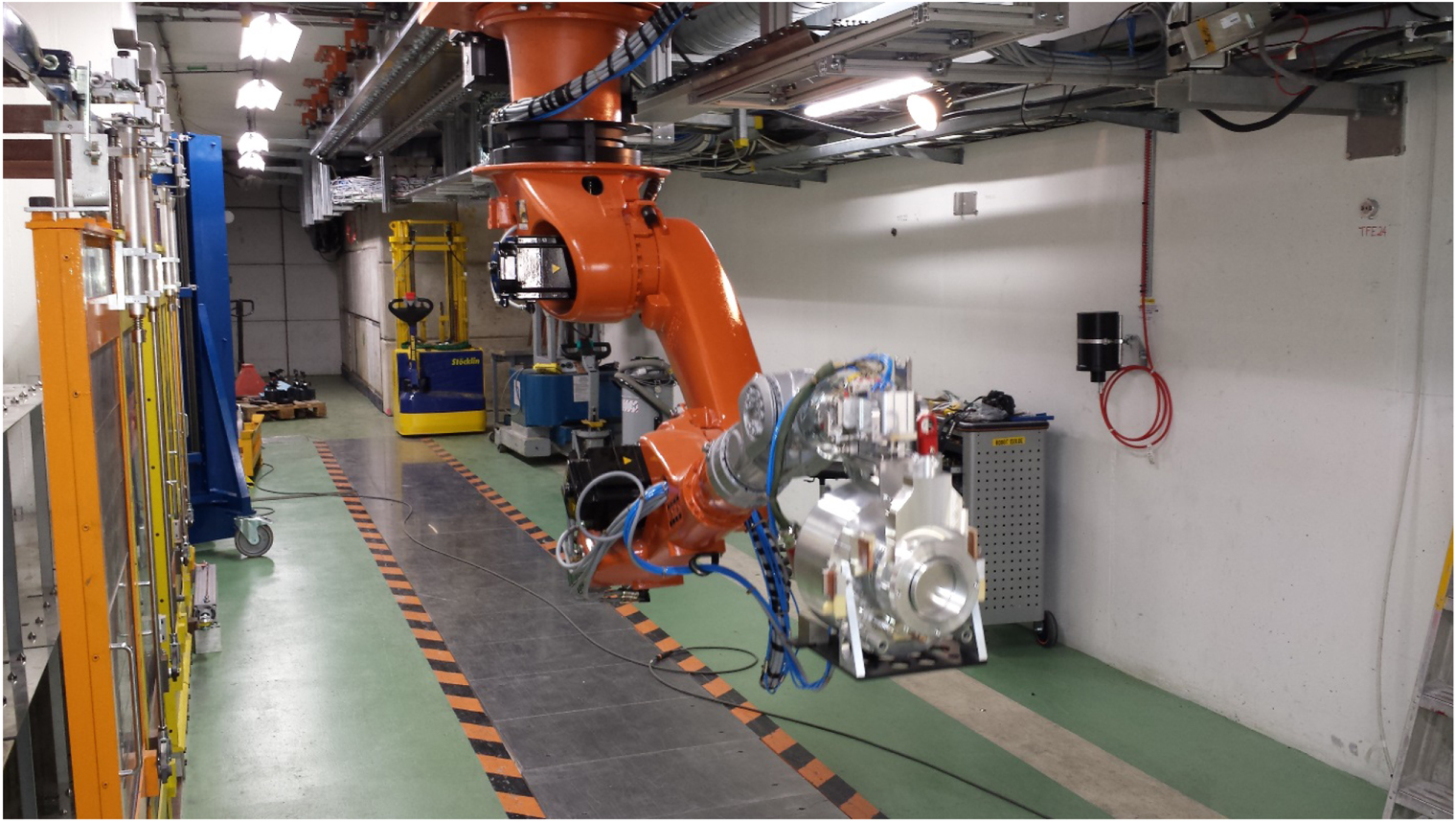
In general, each target is tailor-made to meet the requirements of a specific experiment and with such a diverse physics program at ISOLDE, up to 30 target changes are executed per year. ISOLDE has a tradition of using robots for target handling and when the previous robots had come to the end of their lifetime, a new generation of robots were commissioned in 2014. The two KUKA KR 60L45-3 robots [20] are of a robust design generally used in the foundry industry. By building on the experience gained with the previous robots, the new robots were re-designed and modified to withstand the harsh radioactive environment of the ISOLDE target area. This included the removal of all plastic components and the displacing of electronics cards to a shielded area outside the target area. One novel change with the new robotic handling system is their suspension from the ceiling. The reasoning behind this choice is three-fold; 1. The size of the new robots and the need to negotiate the proton beam line that serves the HRS Frontend to access the GPS Frontend. 2. To provide floor space to facilitate the transport of the mobile target stations during their replacement. 3. To eliminate any risk associated with an obstacle or an eventual water leak in the target area. Robots continue to evolve and the installation at ISOLDE has been able to benefit from this progress. There is a safe mode for in situ calibration and programming, a 'Profisafe' mode for an improved and failsafe communication with different external interfaces such as the Frontends, the storage shelves for used targets, the Faraday cages and the access system. KUKA-Sim, a 3D simulation program, provided the possibility to simulate the robot trajectories in its environment during the design phase of the project. Figure 7 shows the suspended robotic arm transporting a target unit.
For reasons of compatibility and experience, the same KUKA robot has been adopted for the MEDICIS project thus bringing the number of robots used at ISOLDE to three.

Figure 7. The GPS KUKA robot transporting a target unit.
Download figure:
Standard image High-resolution image3.3. Class A laboratories
To provide a safer working environment for the handling of open radioactive sources and with full support from CERN management, the Class A laboratories were commissioned in 2005. Based on recommendations by the Swiss Office Fédérale de la Sante Publique [21], the Class A laboratories were built adjacent to the entrance of the ISOLDE target area and include a laboratory dedicated to the production of actinide targets as well as laboratories for the repair of contaminated equipment. Appropriate changing rooms, decontamination facilities and hand/foot and aerosol monitoring complete the laboratory infrastructure.
3.4. MEDICIS
In 2013, work started on the extension of the Class A laboratories to accommodate the recently approved MEDICIS project. Only approximately 10% of the protons sent to ISOLDE interact with the target; the remaining 90% are directed to the beam dump. The future MEDICIS facility plans to exploit the excess of protons to provide radioisotopes for medical research by placing a second target between the HRS target station and its beam dump. After incidental irradiation, the MEDICIS target is transported to the new laboratory by a dedicated rail conveyor system (RCS) before being placed on an independent mass spectrometer for the production of radioisotopes. This type of parasitic operation will increase the radioisotope production rate while having a minimum impact on the ISOLDE physics program.
The construction of the MEDICIS laboratory has implied a variety of changes to the Class A laboratories and the target area. Its location has required the installation of further shielding and a new access to the target area for the RCS. A third robot system will assure the transport of targets between the RCS, the new target storage area, the MEDICIS Frontend and the alpha–gamma hot cell. Other modifications include combining the MEDICIS and Class A laboratory ventilation systems whilst separating them from that of the target area. This has required the implementation of an access air lock between the Class A laboratories and the target area for improved under-pressure control. The layout of the MEDICIS and Class A type laboratories is provided in figure 8.
At present, work continues on the infrastructure installation with the first irradiations planned for the summer of 2017. The Geneva University Hospital, the Lausanne University Hospital (CHUV) and the Swiss Institute for Experimental Cancer Research (ISREC) of the Swiss Federal Institute of Technology in Lausanne (EPFL), partners of the MEDICIS collaboration, will be the first to take advantage of the radioisotopes provided by MEDICIS.

Figure 8. Plan of Class A and MEDICIS laboratories situated at the entrance of the ISOLDE target area.
Download figure:
Standard image High-resolution image3.5. Alpha–gamma hot cells
The year 2014 saw the installation of an alpha–gamma hot cell destined for the contained dismantling and preparation of previously irradiated targets prior to their shipment to host state facilities for further treatment. The hot cell, shown in figure 9, has two compartments, one for mechanical disassembly of targets and the other for the oxidation of uranium carbide; a safety requirement for long term storage. Each compartment has double door transfer ports, two master-slave telemanipulators and the possibility to work under an inert atmosphere. Lead bricks 15 cm thick from floor to ceiling assures sufficient shielding for the operator while visualization is assured via lead glass windows with athickness of 350 mm.

Figure 9. The alpha–gamma hot cell.
Download figure:
Standard image High-resolution image
4. The design study
After 20 years of successful ISOLDE operation at the PS-Booster, a major upgrade of the facility, the high intensity and energy ISOLDE (HIE-ISOLDE) [22] project was launched in 2010. It is divided into three parts; a staged upgrade of the radioactive experiment (REX) post-accelerator to increase the beam energy from 3.3 to 10 MeV/u using a super-conducting Linac, an evaluation of the critical issues associated with an increase in proton-beam intensity and a machine design for an improvement in RIB quality. The two latter were addressed within the HIE-ISOLDE design study and are summarized in this chapter.
4.1. Energy and intensity increase
While radioactive beam intensities can be increased by improving the efficiency of target and ion source systems, another approach is to increase the driver beam intensity. The future Linac 4 at CERN will be able to deliver to ISOLDE up to 1 × 10¹⁴ compared to the present 3.3 × 10¹³ protons per pulse. In parallel, plans to increase the PS-Booster energy to 2 GeV are under way and a proposal to extend this energy upgrade to ISOLDE has been submitted [23] to the CERN Research Board. Table 4 summarizes the possible scenarios.
Table 4. Projected beam parameters considered within the HIE-ISOLDE design study. Based on ISOLDE receiving 50% of available proton pulses from the PS-Booster.
| Protons/pulse | Current (μA) | Energy (GeV) | Cycle length (s) | Average power (kW) |
|---|---|---|---|---|
| 3.3 × 10¹³ | 2.2 | 1.4 | 1.2 | 3.1 |
| 1 × 10¹⁴ | 6.7 | 1.4 | 1.2 | 9.3 |
| 1 × 10¹⁴ | 6.7 | 2.0 | 1.2 | 13.4 |
Clearly an increase in primary beam intensity and energy will have an impact on the operation and maintenance of the existing facility. Issues addressed included the resistance of target materials, target lifetime, incidental target heating, shielding, air activation, vacuum and interventions, all of which were covered within the HIE-ISOLDE design study.
4.1.1. Beam dumps
One of the critical items associated with an increase of proton-beam energy and intensity are the beam dumps. The existing beam dumps are steel blocks with dimensions 1.6 m × 1.6 m × 2.4 m long (GPS) and 0.4 m × 0.4 m × 1 m long (HRS) surrounded by concrete shielding. The projected scenarios highlighted in table 4 and plans to upgrade the PS-Booster beam dump within the PS-Booster 2 GeV upgrade have initiated investigations concerning the ISOLDE beam dumps [24]. Although the exact heat transfer coefficient around the dumps is unknown, initial studies using the ANSYS numerical code, indicate that the situation will be critical if the HIE-ISOLDE parameters are adopted. In a steady state situation, temperatures have been simulated up to ∼1900 °C for the HRS beam dump and ∼500 °C for the GPS for 13 kW of proton-beam power compared to ¬200 °C and ¬100 °C, respectively, for the present 3 kW of average proton-beam power. Additionally, the compressive stress exerted on the HRS beam dump would exceed the maximum compressive stress of 350 MPa for steel. The estimated compressive stress currently on the HRS beam dump at 3 kW of average proton beam power is 250 MPa. It is clear that new beam dumps, possibly with forced cooling, will have to be installed at ISOLDE prior to any increase in proton-beam intensity or energy.
4.1.2. Air activation and shielding
One of the limiting factors prohibiting the increase in proton beam intensity beyond an average of 2 μA is the amount of activated air released to the atmosphere. One approach to address this binding condition is to improve on the ventilation system and separate the tunnel ventilation system from its neighboring Class A laboratory system. Addressed in the design study, the modification of the ventilation systems and an improvement of the target area leak tightness was done at the start of 2015. Results of the activated air release for 2015 are pending. Further improvements can be achieved the implementation of additional shielding around the beam dumps and would be part of the beam dump replacement project.
4.1.3. Targets and frontends
In this part of the design study, detailed analysis of the thermodynamics of the existing target heating concept was followed by proposals for improvement. Improved target container thermal shielding using graphite felt and the concept of electron bombardment were proposed as novel ideas for the improvement of target performance [25]. Another approach was the adoption of tailor-made target material samples with emphasis on the release properties and their resistance to radiation damage [26].
For the Frontend, emphasis was put on the modeling of a two-staged extraction electrode. This was driven by the annual requirement to exchange the extraction electrode tip due to accumulated condensed matter which in turn contributes to sparking across the acceleration gap. While the concept would reduce the need for interventions and would guarantee a clean extraction electrode tip for every target (the tip would be part of the target unit and not the Frontend), the difficulties in cooling the extraction electrode tip due to its close proximity to the hot ion source and its integration into an existing Frontend has prevented the pursuit of this concept.
4.2. Beam quality
4.2.1. RFQ cooler
The RFQ Cooler, as previously mentioned, has become an integral part of ISOLDE operations. To study improvements, a second RFQ Cooler [27] was built within the design study to be able to fully test its performance after modifications. It will be coupled to a laboratory test bench that replicates all the functionalities of the ISOLDE mass separators and referred to as an off-line separator. A second off-line separator is presently under construction.
4.2.2. HRS separator magnet
In the proposed layout, the HRS is changed to allow for the addition of a pre-separator magnet to reduce the current integrated overall masses, the addition of an RFQ Cooler for beam quality improvement by a radial cooling and a new mass separation magnet. The beam line before and after the magnet is optimized to provide and conserve a small emittance for the magnet to be able to separate the isobars with a mass resolving power of R = m/Δm ∼ 20 000 in the rare earth region of the nuclide chart.
The new magnet design [28] is to first order a dipole for the mass separation, which is provided by the pole gap. The latter has to be machined with a precision of a few microns to avoid an increase of the emittance of the ion beam. The magnet is in addition equipped with 14 pole-face correction conductors to create higher order components of the magnetic field for focusing, compensation of the aberration and the lateral field penetration emittance is conserved passing through the magnet for a certain ion species. Table 5 outlines the characteristics of the new magnet design for a resolving power of 20 000.
Table 5. The main characteristics of a new dipole magnet design for the high resolution separator.
| Bending angle | 120 deg |
|---|---|
| Max field strength | 0.5 T |
| Max mass | 200 u |
| Bending radius | 1.25 m |
| Pole gap | 0.12 m |
| Pole width | 0.50 m |
| Weight | 40 t |
| Outer radius | 2.00 m |
| Height | 1.28 m |
4.2.3. REXEBIS electron gun
The physics proposals for the upgrade of the REX post-accelerator energy require an improved performance of the REX charge breeder electron beam ion source (EBIS) to limit the decay losses of short-lived ions and also to minimize the inevitable dead time of the gamma array detection system due to the pulsed beam structure[29]. In order to increase the efficiency of the data acquisition it is important to provide ion pulses with the highest possible repetition rate, up to the 100 Hz limit of the Linac instead of the present 8 Hz for mass 132 at A/q < 4,5. An increase of the repetition rate requires a corresponding increase in the electron current from 0.2 A to 2–5 A and hence major changes in the EBIS design. The design study project focused on a new double-compression electron beam optics and the challenge was addressed in a joint project with Brookhaven National Laboratory (BNL) who already had a preliminary development and a suitable test bench [30]. In 2013–16, the electron gun was built at CERN and tested on the BNL TestEBIS while in parallel the entire beam optics of the EBIS was studied numerically [31, 32]. The gun underwent several design modifications related to the optics simulations and mechanical structure and in the summer of 2016 the project was concluded with the electron gun delivering a current of 3.14 A [33]. Based on the lessons learned, a project to retrofit a double-compression gun into a test bench replica of the REX charge breeder was started at CERN [34, 35]. As of December 2016, all of the gun components have been manufactured and are being assembled. This design may benefit HIE-ISOLDE by increasing the repetition rate of the extracted multi-charged ion beam tenfold. With more substantial investment including the upgrade of the solenoid magnet from 2 to 6 T, an additional repetition rate increase of 3.5 with no losses in capacity and acceptance could be achieved.
Acknowledgments
ISOLDE was previously under the responsibility of the physics sector but during a CERN-wide restructuring in 2000, the ISOLDE technical team became attached to the Accelerator and Technical Sector (ATS) and the various activities were distributed throughout CERN's support groups. Although change brought about uncertainty, the advantages of moving to the ATS certainly outweighed the disadvantages. ISOLDE benefitted from access to the major support groups and consequently gained visibility as one of CERN's dynamic facilities. Today, CERN's management continues to provide resources for operations and for ISOLDE related projects such as HIE-ISOLDE and MEDICIS. This commitment was also reflected in the CERN management's decision to maintain operations at ISOLDE (and the PS-Booster) during a 12 month stop of CERN's larger machines in 2005.
ISOLDE continues to provide a wealth of physics results thanks to the commitment and investment by many members of the CERN personnel and visiting scientists. The author would like to express his gratitude for their contribution to the ISOLDE facility and to this paper.