

Abstract
We present a liquid phase post synthesis self-assemble protocol that transforms trillions of carbon nanotubes (CNTs) in powder form into densely packed flexible, robust and binder-free macroscopic membranes with a hierarchical pore structure. We employ charge transfer engineering to spontaneously disperse the CNTs in a liquid medium. The processing protocol has limited or no impact on the intrinsic properties of the CNTs. As the thickness of the CNT membrane is increased, we observed a gradual transition from high flexibility to buckling and brittleness in the flexural properties of the membranes. The binder-free CNT membranes have bulk mass density greater than that of water (1.0 g cm–3). We correlate the mass of the CNTs in the membrane to the thickness of the membrane and obtained a bulk mass density of ∼1.11 g cm–3 ± 0.03 g cm–3. We demonstrate the use of the CNT membranes as electrode in a pristine and oxidized single/stacked solid-state capacitor as well as pristine interdigitated microcapacitor that show time constant of ∼32 ms with no degradation in performance even after 10 000 cycles. The capacitors show very good temperature dependence over a wide range of temperatures with good cycling performance up to 90 °C. The specific capacitance of the pseudocapacitive CNT electrode at room temperature was 72 F g–1 and increased to 100 F g–1 at 70 °C. The leakage current of bipolar stacked solid state capacitor was ∼100 nA cm−2 at 2.5 V when held for 72 h.
Export citation and abstract BibTeX RIS
1. Introduction
Carbon nanotubes (CNTs) are candidates for electrode application in energy storage and conversion systems: advanced batteries, supercapacitors and fuel cells [1–13]. The broad interest in CNTs stems from their unique thermal, electrical and mechanical properties, the diverse potential applications they offer, and the fact that the CNTs are ideal prototype to investigate quantum phenomena in one-dimensional systems. CNTs have been shown to exhibit high tensile strength (∼100 GPa) [14, 15] and elastic modulus (∼1.0 TPa) [14, 15], high electrical (∼10–30 kS cm−1) [16] and thermal (∼1500 W mK−1) [17–19] conductivities, stability at moderate temperatures, low density, high aspect ratio (as high as ∼107) and intrinsic maximum surface area (internal and external surfaces) of graphene ∼2600 m3 g−1 [20]. The monolayer atomic structure and accessibility of both external and internal pores provide additional channels to modify the CNT properties by either coating the surface with metal or metal oxide nanoparticles [21–24], non-covalent attachment of molecules or polymers to the surface [25–28], or infiltrating the inner pores with other chemicals [29, 30]. These structural modifications and the unique intrinsic properties have made CNTs promising candidate for numerous applications in the emerging nanotechnologies. Most of these applications require macroscopic structures consisting of cohesively packed trillions of the individual/bundles CNTs. Tremendous advances have been made in transforming the CNTs into bucky paper, mats, yarns and membranes. However, retaining the properties of the individual CNTs in these forms of macrostructured materials is a tremendous challenge. In the case of electrode processing, the use of mechanical compaction and solid state/liquid-phase processing techniques have become the norm of post-synthesis assembly of the CNTs [31–34]. In most cases, the properties of the macrostructured materials are abysmal compared to that of the individual CNTs. Other carbon sources including activated carbon [35–37], graphite [38, 39], graphene [35, 40] and carbon fiber [41] have been used and demonstrated as electrode materials for electrochemical double layer (ECDL) capacitors in aqueous [35–38, 41] and ionic [42–45] electrolytes, as well as in solid state ECDL capacitors [39, 40, 42–46].
Conventional electrodes for electrochemical energy storage and conversion systems usually consist of a mixture of the active electrically conducting material, and a binder to form a paste that is deposited on a metal current collector. The use of CNTs as electrode material in Li ion batteries, electrochemical capacitors and fuel cells [1–13] have been demonstrated. Several techniques have been used in fabricating the CNT electrodes. These involve the direct growth of the CNTs on Ni support [8, 9] or graphitic foils [8, 9] or the used of electrophoresis to deposit the CNT on a metal current collect [7]. In most cases, binders are used to hold the powder together [10–12]. The additional mass of the binder, the conducting material and/or the supporting substrate poses two major performance limitations: the increase in mass itself of the electrode, and the decrease in accessible active surface area. These limitations have been eliminated with the use of CNT 'Bucky-paper' electrodes formed from the filtration of surfactant-dispersed CNTs [31], or the densification of CNT forests via liquid-induced collapse techniques [32], or with the use of super acids [33, 34]. However, the 'Bucky paper' formed are normally flaky, fragile and brittle with low packing density, and swelling has become a major problem in most of these freestanding CNT-based electrodes. Where a binder is used, it decreases the overall performance of the device by increasing the mass and reducing the active accessible surface area. The strong acids tend to lead to functionalization of the CNTs with undesired species and damage to the CNT skeletal structure, degrading the intrinsic properties and quality of the CNTs. Thus, there is lack of a consistent, reproducible and viable scalable process in converting CNT powder into freestanding binder-free macrostructures.
We present a liquid phase post synthesis self-assembly (LP-PSSA) protocol that transforms the trillions of CNTs in powder form into densely packed binder-free macroscopic membranes with hierarchical pore structure that are flexible and robust with limited or no impact on the intrinsic properties of the CNTs, using halogens or halogenated high density organic liquids (Cargille Heavy Liquids). The binder-free CNT membranes have mass density greater than that of water. We correlate the mass of the CNTs loaded in the liquid to the thickness of the membrane formed after the fabrication process and observed a transition near 50 μm, from high flexibility to brittleness in the flexural properties of the membranes. The use of the binder-free CNT membranes as electrode was demonstrated for making both solid-state stacked capacitor as well as interdigitated electrode with very high power density and no degradation in performance after 10 000 cycles.
2. Experimental Details
2.1. Fabrication of binder-free CNTs membrane
2.1.1. Chemical processing of CNTs into membranes
A commercial CNT from Thomas Swan (Thomas Swan Elicarb) of nominal residual content ∼3.5 wt% was dispersed and suspended in liquid bromine under continuous magnetic stirring at 600 rpm for several hours. The liquid was thermally evaporated slowly and trapped cryogenically, resulting in the formation of the binder-free CNT membrane. In this process, we varied the mass of the CNT within the range 30 mg ≤ m ≥ 150 mg in a fixed volume of the liquid bromine (10 cc) and assembled in a 52.0 mm diameter petri dish. CNT concentrations of 30, 60, 90, 120 and 150 mg were prepared under similar conditions.
2.1.2. Purification of CNT membranes
A chlorination protocol was used to digest and extract residual contaminants in the membranes [47]. The membrane was placed inside a two-inch diameter quartz tube mounted in a thermolyne 21 100 horizontal tube furnace. The system was purged with helium at 200 sccm for an hour and then heated to 900 °C at the rate of 50 °C min−1. The gas was switched to a mixed gas: helium/chlorine (95%:5%) for 1 h. This was followed by similar ratio of helium/hydrogen (95%:5%) for 4 h to remove any residual bromine and/or chlorine in the membrane. The system was finally purged at the same temperature under the helium environment for 1 h and cooled down to room temperature.
2.2. Characterization of the CNT membranes
2.2.1. Residual content analysis and Raman spectroscopy
The TA Q5000IR thermogravimetric analyzer (TGA) was used to analyze the residual content of the original Thomas Swan Elicarb CNT powder and the purified CNT membrane. Temperature program oxidation of 5 mg of the commercial as-received powder and the purified CNT membranes were performed at 5 oC min−1 ramp rate from room temperature to 900 °C. Ultra high purity nitrogen gas (99.9999%) was used to purge the balance chamber during the treatment of the CNTs with dry air (99.999%). The flow rate of the dry air and the nitrogen gas were set at 10 ml min−1 and 25 ml min−1, respectively. Raman analysis of the Thomas Swan Elicarb CNT powder and the purified CNT membrane were performed using the Reneshaw inVia Raman spectrometer with the 514 nm laser line.
2.2.2. Surface area and porosity analysis
The Micromeritic ASAP 2020 was used to perform the specific surface area and porosity analysis of the as-received Thomas Swan Elicarb CNT powder and the purified CNT membrane. Prior to the measurement, each sample was degassed at 300 °C at vacuum pressure of ∼10−7 Torr. The density functional theory and the cylindrical pore model option provided with the equipment was used to determine the pore volume and the pore size distribution. The Brunauer Emmett and Teller equation was used to determine the specific surface area of the as-received CNTs and the CNT membranes.
The total pore volume was obtained at 95% of the saturation pressure. The total micropore volume was determined from the DFT analysis, considering pores less than 20 Å, and used the incremental surface area as a function of pore width for the pore size distribution (PSD).
2.2.3. Zygo optical profilometer
A scanning white-light interferometry instrument, the Zygo NV7300 Profilometer was used to analyze the thickness of the CNT membranes. The Zygo consists of an interferometric objective lens mounted on a piezo scanning stage that translates in the vertical direction. The camera positioned at the top of the stage detects interferogram intensities of the sample that are sorted with an interfaced computer to store only the high modulating (>5%) data as a three dimensional interferogram. This is then coupled with a frequency domain analysis that determines the heights of each display pixel to a resolution of <0.1 nm and a repeatability of <0.3 nm.
2.2.4. SEM
The morphological and the chemical composition analysis of the membrane using EDS were collected in high vacuum in an FEI Nano SEM-630. This scope uses a high resolution field emission source and column, along with a monopole magnetic field immersion final lens, allowing for extremely high spatial resolution (up to 1 nm) and exceptional contrast. The SEM images were collected using the beam deceleration technique with the stage bias ranging from 1 to 2.5 keV, allowing for landing energies in the range of 550–2 keV, and incoming electron voltage of 1.5–4 keV.
2.3. Electrochemical testing
For the preparation of the PVA-H3PO4 blend membranes, 1 g of PVA (purchased from Sigma-Aldrich Inc.) was added to 10 ml deionized water. The solution was stirred using magnetic bar at 90 °C for 45 min in order to dissolve the PVA completely. The homogeneous, transparent mixture was then allowed to cool down to room temperature and phosphoric acid of desired amount was added to it. The solution was stirred for 12 h at room temperature before 10 μl of Gluteraldehyde solution (Sigma-Aldrich, 50 wt%) was added as cross-linking agent. The stirred solution was casted on a flat and smooth polypropylene sheet using a doctor blade. The casted membrane was allowed to dry for 3 d, after which it was covered by another polypropylene sheet and was stored under dry atmosphere.
Silica nanoparticles was synthesized using Stober's synthesis method [48]. For the preparation of the PVA-H3PO4-SiO2 composite membranes, 5 μl (3-Aminopropyl)triethoxysilane (APTES) (Sigma-Aldrich, 99%) was added to 10 ml deionized water. The pH of the solution was adjusted to 4 by the addition of 6 μl acetic acid. Thereafter, 0.025 g (2.5 wt% of PVA) of synthesized SiO2 nano-particles was added to the solution and stirred for 24 h at room temperature. The aminopropylated silica nanoparticles were subsequently functionalized by adding phosphoric acid to the solution with the designed amount and stirring for 2 h at 70 °C. 1 g PVA was then added to the homogeneous phosphorylated silica colloidal solution (containing excess phosphoric acid). PVA was completely dissolved by stirring the solution for 45 min at 90 °C, after which the homogenous solution was allowed to cool down to room temperature. Before casting, 10 μl of Gluteraldehyde solution (Sigma-Aldrich, 50 wt%) was added to the solution as cross-linking agent. The casting and storage process was identical to the preparation method described above.
Two identical CNT electrodes (area ∼19 mm2) were sandwiched together using the synthesized polyvinyl alcohol/H3PO4 membrane. Two grafoil films (purchased from MTI corporation) were used as current collector. The assembled structure was sealed using a masking tape and pressed slightly using a pressure of 0.25 ton using a hydraulic press in order to obtain good contact between each layer of the structure. In order to make stacked capacitor, grafoil current collectors were used as bipolar current collectors and three identical symmetric solid state cells were stacked and pressed together. For a 20 μm thick CNT electrode, the typical mass loading was 1.5 mg cm−2.
In order to prepare ox-CNT electrode, the as prepared CNT electrodes were mildly oxidized by soaking in 0.002 M KMnO4 aqueous solution at 60 °C for 20 min. The soaked electrodes was further immersed in 1 M H2SO4 to remove any manganese residues and the electrodes were heat treated at 100 °C in an oven overnight [49].
A Gamry Reference 3000 potentiostat/galvanostat was used to test the solid state capacitors. Cyclic voltammetry were done at different scan rate ranging from 10 mV s−1 to 1 V s−1 within a scan range of 0–1 V. EIS measurements were performed by varying the frequency from 105 to 10−3 Hz. Constant current charge/discharge cycling was done to determine the specific capacitance and cycling performance.
Using the binder-free SWCNT membranes, a single-step laser cutting protocol was used to fabricate interdigital electrodes. Many of the processes used to develop interdigital electrodes involve several time-consuming nanofabrication techniques, often including lithography [50–53]. This laser-cutting method was able to cut interspaces of 50 μm or less, on the same order as the electrodes developed using lithography methods. This process is highly repeatable and can be controlled based on the thickness of the membrane.
3. Results
We show in figure 1 optical images of two sets of the CNT membranes (flexible membranes: CNT-FMs and brittle membranes: CNT-BMs) fabricated under the same conditions using the steps outlined in sections 2.1.1 and 2.1.2 above. The CNT-FMs in figure 1(a) are extremely flexible and robust. These membranes have thicknesses less than 45 μm. On the other hand, the CNT-BMs in figure 1(b) of thicknesses ≥55 μm are buckled and brittle, even though the processing protocols for both sets of membranes were the same. We will elaborate more on the differences later. For clarity, we will use CNT-FMs for the flexible membranes and CNT-BMs for the brittle CNT membranes in referring to figures 1(a) and (b), respectively.
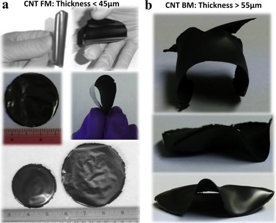
Figure 1. Optical images of collection of binder-free (a) flexible and robust CNT membranes (CNT-FM) of thickness <45 μm, and (b) buckled and brittle CNT membranes (CNT-BM) of thickness >55 μm. These two sets of CNT membranes were fabricated under the same conditions using the liquid phase post synthesis self assemble (LP-PSSA) protocol.
Download figure:
Standard image High-resolution imageIn figure 2(a), we show an SEM image of the surface morphology of the smooth and shiny surface (surface in contact with the petri dish) of CNT-FM. It reveals densely packed and randomly oriented CNTs in the in-plane of the membrane. Figure 2(b) is a filtered image of figure 2(a) into a two-dimensional black–white mode for clear distinction of the empty spaces (voids) at areas where there are no CNTs. This was done using threshold adjustment of an image analysis software, ImageJ [54]. The black regions correspond to the voids in the original image (figure 2(a)). A two-dimensional statistical distribution analysis of the area of the voids using the image analysis software, ImageJ [54] is shown in figure 2(c). The average total area of the voids from several SEM images irrespective of the thickness of the membrane (10 μm ≤ t ≤ 45 μm) was estimated to be ∼16% ± 1%.

Figure 2. (a) SEM image of the surface morphology of a CNT-FM, (b) filtered image of (a) using an image analysis software (imageJ) for void analysis, (c) area distribution of voids in figure (b), (d) an SEM image of a broken edge of a CNT-FM revealing a densely packed and stacked layers in the membrane, and (e) a cross-sectional SEM image of a piece of a CNT-FM.
Download figure:
Standard image High-resolution imageSimilar analysis of several SEM images of the smooth side of the brittle CNT membranes gave an estimate of ∼17% ± 1% of voids. On the other hand, the average area of the voids on the dull side of several SEM images of both flexible and brittle CNT membranes was estimated to be ∼20% ± 1%. This difference might be due to the surface roughness of the top surface of the membranes. Figure 2(d) shows an SEM image of a broken edge of a CNT-FM that reveals densely packed and stacked layers in the membrane. Figure 2(e) is a cross-sectional SEM image of a piece of a CNT-FM of thickness ∼32 μm. The thickness of the membranes was measured with a non-distractive and non-contact optical profilometer, Zygo NV7300. The 3D, the 2D and the line profile analysis of a piece of CNT-FM using the optical profilometer are shown in figures 3(a)–(c), respectively.

Figure 3. (a) The 3D, (b) the 2D, (c) the line profile analysis of a piece of a CNT membrane using the optical profiler, (d) a plot of the mass (m) of CNT versus the CNT membrane thickness (t), and (e) EDS mapping of as received CNT powder (before processing) and CNT membrane (after processing).
Download figure:
Standard image High-resolution imageShown in figure 3(d) is a plot of the variation of the mass of CNT in the processing liquid (m) versus the CNT membrane thickness (t) as determined from the optical profiler measurements for membranes processed under the same conditions, and assembled in the same processing dish (diameter ∼52 mm). There was very limited mass loss due to the processing, on average, about 1% of the loading mass. Each data point represent the average thickness of five membranes prepared using the same amount of mass per loading and under similar conditions. The error bars indicate the spread. The plot (solid dots) in figure 3(d) reveals a linear relationship between the mass loading (m) of the CNTs and the thickness (t) of the CNT membranes. The solid line is the least square fit of the data. The slope (s) from the fit is ∼22.58 g cm–1. From the slope (s), we estimated the bulk mass density of the membranes to be ∼1.11 g cm–3 ± 0.03 g cm–3 using the expression m = ρV = (ρπD2/4)t. Where s = ρπD2/4, V is the volume of the membrane, D is the diameter of the membrane (∼diameter of the processing dish), t is the thickness of the membrane and ρ is the bulk mass density of the membrane. We have already demonstrated that the mass density of the membrane is greater than that of water (∼1.0 g cm–3) [49]. In figure 3(e) we show the EDS spectra of the as-received CNTs (left plot) and a CNT membrane (right plot). The Kα and Lα peaks of Fe near 0.7 and 6.4 keV are almost non-existence in the spectrum collected from the CNT membrane. This was observed in all membranes irrespective of flexibility or brittleness. The removal of the residual contaminants, mainly metal catalyst is critical to the electrochemical performance of the CNT membranes as electrode in energy storage and conversion systems. The improvement in sample quality was also confirmed with TGA and Raman [49].
Interestingly, the membranes become brittle as the thickness increases. We observed that the membranes with thicknesses t ∼ ≤ 45 μm seem to be more flexible (see figure 1(a)). However, we also observed a gradual transition from highly flexible and robust membrane to buckling and brittleness as the thickness increases, as shown in figure 1(b). Strong buckling and brittleness occurred in membranes with thicknesses ∼≥55 μm (figures 1(b) and 3(d)). We observed that the thinner the membranes, the uniform the drying process. As the thickness increases, the drying becomes nonuniform, which could induce strain in the membranes, leading to the buckling. Additionally, in the thinner membranes, the CNTs are mostly oriented and interwoven in the in-plane direction. However, as the thickness of the membrane increases and approaches the length scales of the CNTs, more and more CNTs might be oriented in the out-of-plane direction, which might lead to the buckling and the brittleness during the drying process.
A comparison of the nitrogen adsorption (solid maker) and desorption (open markers) of the three types of CNT samples are shown in figure 4(a), CNT powder (square markers), CNT-FM (circle markers) and CNT-BM (triangle markers). The hysteresis in the three samples suggests the presence of meso- and macro-pores. The hysteresis is more pronounced in the CNT-BM sample. The BET surface area of the CNT powder, the CNT-BM and the CNT-FM are 744 m2 g−1, 798 m2 g−1 and 792 m2 g−1, respectively, as determined from the BET plot shown in figure 4(b) (CNT powder: squares, CNT-BM: triangles and CNT-FM: circles). The relatively small increase from the powder to the membranes might mostly be due the change of 'state', clusters in powder form to interwoven in membrane. This also suggests that the processing protocol did not have much effect on the CNTs skeletal structure, since we accessed only the external surfaces in both the powder and the membranes. The fact that there is no difference between the BET of the CNT-FM and CNT-BM suggests the consistency and repeatability of the protocol. Figures 4(c) and (d) show the deduced cumulative pore volume (top plot) and the differential pore volume (bottom plot) using the DFT adsorption analysis (CNT-FM: solid curve, CNT powder: dash dot curve and CNT-BM: dash curve). The CNT powder and CNT-FM show broad distribution of mesopores (20–50 Å) and large amount of macropores >50 Å. The pore size in the CNT-BM in the micropore region is shifted up a bit compared to that of CNT powder and CNT-FM.

Figure 4. A comparison of the nitrogen adsorption and desorption properties of the CNT powder and the binder-free CNT membranes (a) isotherms, (b) BET plot, (c) deferential pore volume, and (d) cumulative pore volume.
Download figure:
Standard image High-resolution imageFigure 5 shows the TEM micrograph of microtomed crosslinked PVA-H3PO4 gel electrolyte membrane. The micrograph shows distinct segregation of phosphoric acid domains in the PVA matrix in the order of 1–2 μm. The phosphoric acid domains was well dispersed throughout the PVA matrix. In order to improve the mechanical properties of the membrane, small amount of phosphorylated silica (2.5 wt%) was added to the membrane. The synthesis of the nanocomposite is illustrated in figure 5.
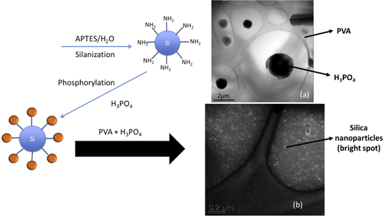
Figure 5. Schematic of synthesis of silica modified PVA-H3PO4 proton conducting composite membrane.
Download figure:
Standard image High-resolution imageThe synthesized silica nanoparticles were in the order of 10 nm and were uniformly dispersed in the PVA matrix. The ionic conductivity of the membranes measured at room temperature generally increased with increasing in the phosphoric acid content. The maximum content of phosphoric acid was limited to ∼67 wt% in unmodified PVA-H3PO4 as further addition significantly deteriorated the mechanical properties of the PVA making it harder to peel off the tape casted membranes. The thickness of the membrane was ∼80 μm. With the addition of silica, the phosphoric acid content increased to ∼72 wt% and the membranes could also be casted as thin as 20 μm. The maximum ionic conductivity achieved at 298 K for unmodified PVA-H3PO4 membrane and silica modified PVA-H3PO4 was 1.44 × 10⁻² S cm−1 and 3.18 × 10⁻² S cm−1, respectively. The temperature dependence on ionic conductivity of the membranes was fitted using Vogel–Tamman–Fulcher model as follows:  where
where  EA is activation energy, kb is Boltzmann constant, σ0 is pre-exponential factor and T0 is the ideal glass transition temperature as shown in figure 6.

Figure 6. Comparison of the ionic conductivity as a function of temperature of PVA-H3PO4 composite membrane with and without silica. Inset: fitted VTF model parameters for PVA-H3PO4 composite membrane with and without silica.
Download figure:
Standard image High-resolution imageThe insert table summarizes the values of various model parameters for both unmodified PVA-H3PO4 and silica modified PVA-H3PO4 membrane. For similar loading of phosphoric acid, addition of silica lowered T0 while increasing the value of σ0. The value of T0 corresponds to the temperature at which ionic motion becomes completely hindered while increase in σ0 suggests increased concentration of charge carriers. The value of Ea indicates that the predominant transport is related to proton hopping (Grotthus mechanism) [55].
The fabricated CNTs and PVA-H3PO4 membranes were then used as electrodes to construct all solid-state electrochemical capacitors. Figure 7(a) shows the constant current charge/discharge plot of capacitor made using 20 μm thick electrode and solid state PVA-H3PO4 membrane being cycled at 5 A g−1. The specific capacitance of the electrode was ∼48 F g−1.

Figure 7. (a) Charge/discharge curve of solid state CNT capacitor cycled at 1 A g−1 between 0 and 1 V, (b) specific capacitance of CNT capacitor as a function of current densities ranging from 0.5 to 20 A g−1. The capacitor was cycled at each current density for 100 cycles, (c) specific capacitance of CNT capacitor as a function of temperature ranging from 20 °C to 100 °C. The capacitor was cycled at each temperature for 200 cycles.
Download figure:
Standard image High-resolution imageThe solid state capacitor was cycled at various current densities and showed 92% capacitance retention even at high current densities of 20 A g−1 as shown in figure 7(b). The solid state capacitor also showed excellent cyclability when cycled at high temperature upto 80 °C as shown in figure 7(c). In order to increase the specific capacitance of the CNT electrode, the CNT membranes were slightly oxidized using 0.002 M KMnO4 solution and this resulted in an increase in specific capacitance of the electrode to almost 72 F g−1, which corresponds to almost 50% increase in capacitance.
The solid state capacitors made using both as prepared CNT and oxidized CNT showed excellent cycling stability up to 10 000 cycles as shown in figure 8(a). We also saw that unlike the pristine CNT, the capacitance increased with increasing temperature for the oxidized CNT. The specific capacitance of ox-CNT almost increased to 100 F g−1 at 70 °C while the capacitance of pristine CNT remained invariant with temperature as shown in figure 8(b). The temperature dependence of the ox-CNT shows induced pseudocapacitance introduced by the oxygen surface functional groups on CNT during KMnO4 treatment. This is also consistent with the measurement of the time constant of the solid state capacitors which shows that with the oxidation of CNT, the time constant increases from 31.8 ms (pristine CNT) to 0.79 s (figure 8(c)).
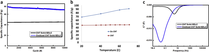
Figure 8. (a) Comparison of cycling performance of solid state CNT capacitor and ox-CNT capacitor for 10 000 cycles, (b) specific capacitance as a function of temperature for solid state CNT and ox-CNT capacitor and (c) comparison of the imaginary plot of capacitance as a function of frequency of solid state CNT and ox-CNT capacitor illustrating shift in time constant.
Download figure:
Standard image High-resolution imageFigure 9 shows the electrochemical performance data of 3-stacked CNT solid state capacitors. Three solid state capacitors were stacked in series using grafoil as bipolar current collector. The stacked capacitor was capable of being charged and discharged from 0 to 3 V as demonstrated by the cyclic voltammogram in figure 9(a). Constant current charge/discharge with discharge time in the order of 10 s and good cyclability with almost 85% capacitance retention over 10 000 cycles at 70 °C was also demonstrated (figures 9(b) and (c)). The measured time constant of the capacitor was 0.3 s (figure 9(c)) and the leakage current of the capacitor when held at 2.5 V for 72 h was ∼100 nA cm−2 (figure 9(d)).
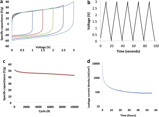
Figure 9. (a) Cyclic voltammagram of 3-cell stacked solid state capacitor measured at 10 mV s−1, (b) charge/discharge curve of bipolar stacked solid state CNT capacitor cycled between 0 and 3 V at 0.3 A g−1, (c) specific capacitance as a function of cycling when cycled between 0 and 3 V at 70 °C, (d) leakage current of stacked capacitor measured at 2.5 V for 72 h.
Download figure:
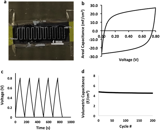
Standard image High-resolution imageIn figure 10(a) we show a laser scribed interdigitated electrodes with a gap space of ∼85 μm. The galvanostatic charge/discharge curve is shown figure 10(b) for a device with 45 μm thick electrodes with minimal IR drop. The cyclic voltammogram in figure 10(c) is nearly rectangular at 500 mV s−1, and shows an areal capacitance reaching 26.9 mF cm−2. The volumetric capacitance shown in figure 10(d) indicates stability of the device at ∼4.52 F cm−3 over 200 cycles. The areal capacitance exceeds that of CNT-based microcapacitors, however, our device needs fine tuning in the energy and power densities [40]. We obtained energy and power density of 0.399 mWh cm−3 and 16.88 mW cm−3, respectively, while Lin et al reported an energy and power density of 2.42 mWh cm−3 and 46 W cm−3 using a CNT forest on graphene current collectors [52].
Figure 10. (a) Optical image of interdigitated device, (b) cyclic voltammogram at 500 mV s−1 scan rate, (c) galvanostatic charge/discharge cycling of the device, and (d) volumetric capacitance as a function of cycling.
Download figure:
Standard image High-resolution image
4. Discussion
This paper presents a unique post synthesis protocols to self-assemble CNT powder into ultrathin flexible membranes that has several potential applications. The LP-PSSA technique present a unique protocol that eliminates the need for binders to hold the CNT powder together. The protocol can be used to assemble binder-free macro-size membranes of other carbon-based structures such as graphene, nanofibers, nanoparticles and their combinations. It involves a process of spontaneous self-assemble of the CNTs by a charge transfer mechanism via wet chemistry processing protocol. Most of the reported wet chemistry techniques end up functionalizing the CNTs or degrading the structural and the physico-chemical properties of the CNTs [33, 34]. Our approach uses charge transfer mechanism to induce the self-assembly. The charge transfer weakens the van der Waals interactions between the tubes, preventing agglomeration and facilitating the random interwoven assemble (figures 2(a), (b)). In addition to the liquid facilitating the self-assembly, it should have limited or no impact on the physico-chemical properties of the CNTs.
We report such charged transfer mechanism using liquids such as bromine to create an interwoven CNT membrane that is highly dense, flexible, binder-free and robust with bulk mass density greater than that of water [49]. Bromine is a mild etchant and has high electron affinity (electron accepter) that can easily induce charge transfer. It is well known that when bromine interacts with CNT, it transfers electrons from the carbon π states, creating a partial charge transfer between the CNT and the bromine [30]. This charge transfer mechanism weakens the van der Waals interactive force between the CNTs that allows uniform dispersion of the CNTs in the liquid bromine. This charge transfer mechanism prevents agglomeration and clustering of the CNTs, leading to homogeneously distributed CNTs in the bromine. The high aspect ratio of the CNT, in addition to the weakened van der Waal forces and the density of bromine being greater than that of the CNTs, cause the CNTs to self-assemble into a floating film on the surface of the bromine liquid. Removal of the excess bromine via evaporation and cryogenic trapping, results in the production of a high packing density, robust, flexible and binder-free CNT membrane. The excess bromine is easily removed at low temperatures ∼45 °C. Treatment at high temperature in the presence of hydrogen gas removes any residual bromine, other functional groups and improves the quality of the CNTs [49]. As can be seen in figure 3(e) (left image), there is no presence of bromine and chlorine Lα peaks near 1.5 keV and 2.6 keV, respectively. Furthermore, the Kα and Lα peaks of Fe near 0.7 keV and 6.4 keV are almost non-existence in the spectrum collected from the CNT membrane. These clearly indicate that the purification protocol outline in section 2.1.2 was effective in removing contaminants (bromine, chlorine, iron) in the CNT membranes. Halogenated high density organic liquids (Cargille) can also be used to assemble the CNTs. The high mass density, the SEM, the Zygo, and the BET data indicate a process with high consistency and repeatability. This is also consistent with the Raman and the TGA data [49].
The flexibility of the CNT membranes depends on the thickness of the membranes in relation to the length scales of the CNTs. The process reveals a transition in the flexural properties of the membranes from high flexibility to brittleness. The flexibility decreases gradually with increasing membrane thickness. All the membranes with thicknesses <45 μm seem to be flexible (figure 1(a)), whereas, as the thickness increases, the membranes become more brittle and buckling (figure 1(b)) after the processing. We suspect that as the thickness of the membrane increases, uneven stresses are induced in the membrane due to the nonuniformity in the drying of the membrane and the increase in out-of-plane oriented CNTs, which could lead to the brittleness and the buckling. The nonuniformity in the drying pronounces with increasing membrane thickness.
The CNT membranes show hierarchical pore structure (micro-, meso- and macropores) as shown in figure 5. We have used such membranes as electrodes to demonstrate symmetric, oxidized and micro (interdigitated) solid state ultra-capacitors (figures 7–10) with time constants (∼32 ms) approaching other carbon based electrolytic capacitors [49–63]. The specific capacitance of electrodes with varying thicknesses from 20 to 60 μm was invariant, and was ∼72 F g−1. We, thus envision the use of the fabricated ultrathin CNT-based membrane as potential current collectors or scaffolds with high chemical stability to deposit redox active materials for both high power flexible battery and supercapacitor applications.
5. Conclusions
Our proposed self-assembly protocol and the results reveal new insights that can be applied to other nanostructures. We have shown in this investigation that it is possible to fabricate macrosize flexible binder-free CNT membranes that are easy to handle. The flexibility depends largely on the thickness of the membrane, and decreases with increasing thickness. However, properties such as the density and the surface area are independent of the nature of the membrane, flexibility or brittleness. Charge transfer engineering of the CNTs is a critical component in achieving dispersion and a densely packed membrane with bulk mass density greater than that of water. The use of mild etchant restricted the degradation of the intrinsic properties of the CNTs in the macrosize membranes. The protocol, shows very high consistency and repeatability. The CNT membranes have the potential to be used as scaffolds to deposit other materials for use in catalysis, photovoltaic, thermoelectric and many other applications, as we have demonstrated for ultrahigh power single, stack, oxidized and interdigitated solid state ultra-capacitors.
Acknowledgments
The authors would like to acknowledge the Center for Dielectric and Piezoelectrics (CDP) and NSF Nanosystems Engineering Research Center for Advanced Self-Powered Systems of Integrated Sensors and Technologies (ASSIST) for their financial support. We would also like to thank the NSF MRSEC Materials Research Facility Network (MRFN) Faculty Program at The Pennsylvania State University Materials Characterization Laboratory (MCL) for providing the financial support for characterization facilities to study the properties of the CNT membranes, and Penn State Altoona Office of Research and Sponsored Programs for their financial support of the undergraduate students engaged in this research.