

Abstract
By applying the asymmetric magnetic field to a discharge, the dc self-bias and asymmetric plasma response can be generated even in a geometrically and electrically symmetric system. This is called magnetical asymmetric effect (MAE), which can be a new method to control the ion energy and flux independently (Yang et al 2017 Plasma Process. Polym. 14 1700087). In the present work, the effects of magnetic field gradient, gas pressure and gap length on MAE are investigated by using a one-dimensional implicit particle-in-cell/Monte Carlo collision simulation. It found that by appropriately increasing the magnetic field gradient and the gap length, the range of the self-bias voltage will be enlarged, which can be used as the effective approach to control the ion bombarding energy at the electrodes since the ion energy is determined by the voltage drop across the sheath. It also found that the ion flux asymmetry will disappear at high pressure when the magnetic field gradient is relative low, due to the frequent electron-neutral collisions can disrupt electron gyromotion and thus the MAE is greatly reduced.
Export citation and abstract BibTeX RIS
1. Introduction
Capacitively coupled plasma sources (CCPs) have been studied for many years due to their widespread usage in the semiconductor industry [1–3]. In plasma processing, high ion energy for etching and low ion energy for deposition are needed, thus the flexible adjustment of ion bombarding energy at the electrodes is always a key issues. To meet the demands for manufacturing process, independently control of ion bombarding energy and ion flux is highly desired. This can be realized in dual frequency discharges [4–6], in which a high-frequency and a low-frequency source are used to drive one or both electrodes. The high frequency controls the ion flux, while the low frequency controls the ion bombarding energy. However, many recent studies [7, 8] have shown that the method of coupling two frequencies is limited.
Asymmetric discharge is accordingly proposed. The dc self-bias is generated naturally to control the ion bombarding energy at the electrodes, since the ion energy is determined by the voltage drop across the sheath. The geometrical asymmetry in CCPs can produce a dc self-bias, in order to compensate the electron and ion flux to each electrode within one rf period which is caused by the difference of electrode areas [9–12]. The geometrical asymmetry effect is limited in practical applications, because it does not allow to adjust the dc self-bias without changing the amplitude of the applied rf voltage waveform. Different voltage amplitude will change the ion flux. Thus, the geometrical asymmetry effect does not allow separate control of ion bombarding energy and ion flux. Subsequently, a more flexible method, i.e. the electrical asymmetry effect (EAE) in geometrically symmetric discharges is proposed by Heil et al [13]. According to the definitions in the literature [14], the EAE can be distinguished into two categories, i.e. (i) amplitude asymmetric effect, and (ii) slope asymmetric effect. For the former, the EAE is generated by using voltage waveforms with different maximum and minimum excursions [15–21]. For the latter, the EAE is generated by using temporally asymmetric waveforms (for example, with different rising and falling slopes) even if the maximum and minimum excursions are equal [22–25]. They have verified the ability to separate control the ion flux and energy both numerically and experimentally.
Recently, magnetical asymmetric effect (MAE) is proposed by Yang et al [26]. By applying the asymmetric magnetic field to the capacitive discharge, i.e. a magnetic field parallel to the electrodes with different magnetic field strength at both electrodes, asymmetric plasma response and self-bias voltage can be generated even in the geometrically and electrically symmetric system. They have shown that the MAE can produce controllable asymmetry in the ion flux and plasma density profiles to each electrode and a significant change on the ion energy distribution functions (IEDFs) at the powered electrode. They also have demonstrated that the MAE is a new method to increase the ion flux and still make the ion energy be adjusted in a certain range. Indeed, inhomogeneous static magnetic field is first used to generate the asymmetric plasma response by studying the IEDFs impinging the electrodes and the sheath dynamics [27]. In the experiment or practical applications, the asymmetric magnetic field can be physically achieved by using solenoid coils. The strength of the field inside can be controlled by adjusting the current in the wire and the fineness of the field gradient also can be controlled by the number of solenoids. Besides, the magnetic field gradient can be made by the permanent magnets with different shaped ends. In microelectronic industry and fundamental physics research, magnetic field plays an important role in improving the plasma parameters and the magnetized CCPs have been widely used. External magnetic field is applied parallel to the electrodes to increase the efficiency of power deposition to the plasma and enhance plasma confinement, which will result in an increase in plasma density [28]. A large number of studies have been devoted to investigating the effects the uniform magnetic field. However, in realistic plasma processing, the magnetic field may not be uniform over the whole discharge space, which could strongly affect discharge asymmetry. Therefore, the study of inhomogeneous magnetic field is more practical.
Here, important questions are raised; what is the control range of the dc self-bias and what is the optimum condition to induce the strongest MAE? Therefore, in this work, we investigate the dc self-bias and ion properties at different conditions i.e. magnetic field gradient, gas pressure, and gap length, by using a one-dimensional implicit particle-in-cell/Monte Carlo collision (PIC/MCC) simulation. The paper is outlined as follows: in section 2, the basics of the PIC/MCC simulation and discharge parameters used in this work are outlined. In section 3, the main results at different conditions are presented and the relevant mechanism will be discussed in detail. Finally, a brief conclusion is given in section 4.
2. PIC/MCC model
The simulation results are based on our one-dimensional implicit PIC/MCC simulation code, which has been described in detail and widely tested before [29–33]. The code considers one spatial coordinate and is three-dimensional in velocity space, thus the E × B drift is correctly simulated. The self-bias voltage is self-consistently determined in the simulation in an iterative way to ensure that the net current to the two electrodes per one rf cycle is zero [34, 35]. It should be noted that there are some limitations of using a 1D PIC code to correctly model E × B dynamics [36, 37]. The electron conductivity along a magnetic field can be orders of magnitude higher than the conductivity across the magnetic field, so the electrons may reach the radial walls first on average than the axial walls. This may lead to the Simon effect, etc. Besides, due to the E × B motion, space-charge separation can occur, which will lead to the generation of an electric field in the E × B direction. This can only be correctly modeled in a 2D PIC [38, 39]. 2D and 3D simulation will be built in our future work and the transport will be included and discussed in detail.
The initial density is uniformly set as n0 = 1 × 10¹⁶ m−3 and 400 particles are put in each cell. The implicit PIC model allows much larger space and time steps than an explicit method, thus the time steps dt for both electrons and ions are fixed as 1 × 10⁻¹⁰ s and the space step dx is fixed as 3.125 × 10⁻⁴ m. At B = 100 G and for a 2 eV electron, the electron gyration radius is about 0.48 mm, thus the electron gyration radius can be accurately resolved. In addition, a standard MCC model is adopted [40] to deal with the collisions process. The reactions for argon gas taken into consideration are elastic, excitation, ionization collisions for electrons, and elastic, charge transfer collisions for Ar+ ions, respectively. The cross sections data are adopted from [41]. Generally, more than 3000 rf periods are needed for convergence due to the presence of magnetic field. After the plasma arrives at its equilibrium, the final results are obtained by averaging over 200 rf periods.
In the following sections, we will study the effects of magnetic field gradient, gas pressure and gap length on plasma characteristics. Geometrically and electrical symmetric discharges are simulated with two parallel electrodes. The reactor is filled with argon gas with a temperature of 300 K. One electrode (at Z = 0) is applied a single-frequency sinusoidal voltage source with a frequency of 13.56 MHz and a voltage of 150 V, while the other electrode is grounded. The magnetic field is applied parallel to the electrodes with different magnetic field gradient. The secondary electrons emission coefficient is considered to be 0.2 in this simulation. When studying the effects of magnetic field gradient, the gas pressure and gap length is set as 30 and 3 cm, the magnetic field strength at the grounded electrode Bg varies from 50 to 400 G while the magnetic field strength at the powered electrode Bp keeps constant of 10 G. When studying the effects of gas pressure, the magnetic field gradient and gap length is set as 10–50 G and 3 cm, the gas pressure varies from 30 mTorr to 400 mTorr. When studying the effects of gap length, the magnetic field gradient and gas pressure is set as 10–100 G and 30 mTorr, the gap length varies from 2 to 10 cm.
3. Results and discussion
Before discussing the effects of parameter variations, we first briefly review the main physical mechanism of self-bias that can be formed by magnetic field gradient. We introduce the theoretical model for the EAE, which has been described in details in the literature [13]. The self-bias η can be derived as  , where
  and
and  are the mean ion sheath densities at the powered and grounded electrodes, V0 is the applied voltage amplitude. According to the theoretical model, if in the geometrical or electrical asymmetry CCP systems, the ion sheath densities at these two electrodes are not equal, and thus a self-bias voltage will be produced. If in the completely symmetric CCP systems, the ion sheath densities should be equal and no self-bias form. When the asymmetric magnetic field is applied, i.e. a magnetic field parallel to the electrodes with different magnetic field strength at the powered and grounded electrodes, the ion flux on the grounded electrode is significantly different with that on the powered electrode, thus a self-bias voltage can be generated even in the geometrical or electrical symmetry CCP systems.
3.1. Magnetic field gradient
First, we study the effects of magnetic field gradient on plasma characteristics. Figure 1(a) shows the time-averaged ion flux  profile for different magnetic field gradient at the gas pressure of 30 mTorr. As one can see, the ion flux increases clearly with the magnetic field gradient at both electrodes. When the magnetic field is uniform in the discharge space, the point y0 where the ion flux is equal to zero should be in the center of the discharge [23]. When the magnetic field gradient is applied, asymmetric plasma response is naturally generated. The point y0 moves closer to the grounded electrode as magnetic field gradient is increased. The ion flux on the left of point y0 is directed toward the powered electrode and on the right it is directed toward the grounded electrode. Figure 1(b) shows the time-averaged ionization rate profile for different magnetic field gradient at the gas pressure of 30 mTorr. It can be seen that ionization occurs at both sheath edge. Two ionization peaks clearly show an asymmetric plasma response, in which the one near the grounded electrode is higher than the one near the powered electrode. The difference between two ionization peaks gets large when the magnetic field gradient increases. This explains why the point y0 moves closer to the grounded electrode as magnetic field gradient is increased.
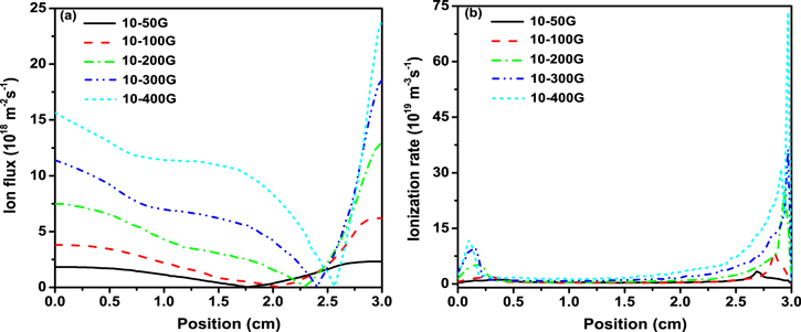
Figure 1. Time-averaged (a) ion flux  and (b) ionization rate profiles as a function of the magnetic field gradient at the gas pressure of 30 mTorr.
Download figure:
Standard image High-resolution imageFigure 2 shows the time-averaged potential distribution as a function of the magnetic field gradient at the gas pressure of 30 mTorr. As we known, when the ion flux at the powered electrode and the grounded electrode are not equal, a voltage drop is needed to ensure the particle-flux balance. From the figure 2, we can see that the dc self-bias voltage is formed at the powered electrode, which corresponds to the ion flux profile observed in figure 1(a). The self-bias voltage can be used as the effective approach to control the ion bombarding energy at the electrodes, since the ion energy is determined by the voltage drop across the sheath. Also, it is possible to change the sign of the self-bias by reversing the magnetic field gradient. It should be highly desirable in plasma processing.
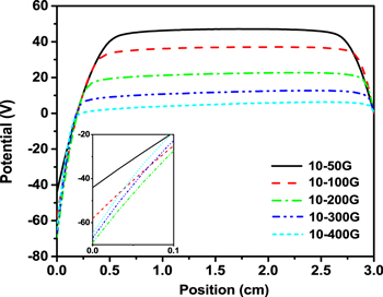
Figure 2. Time-averaged potential profile as a function of the magnetic field gradient at the gas pressure of 30 mTorr.
Download figure:
Standard image High-resolution imageIn figure 3, the black line with square shows the dc self-bias voltage as a function of the magnetic field strength at the grounded electrode Bg at the gas pressure of 30 mTorr, when the magnetic field strength at the powered electrode Bp keeps constant of 10 G. It can be clearly seen that the self-bias voltage grows first and then decreases as the magnetic field strength Bg increases, with a maximum occurs at 200 G. The self-bias voltage can be as high as 70 V, which is 47% of the applied voltage amplitude. The red line with circle shows the ratio of the time-averaged ion fluxes  at the grounded electrode and powered electrode as a function of the Bg. The trend of the ratio
  is basically consistent with the trend of self-bias voltage, because the dc self-bias formation is the result of a particle-flux balance applied to each electrode and the influence of gradient drift [26]. Therefore, by adjusting the magnetic field gradient, the range of self-bias voltage can be controlled, thus the flexible adjustment of ion bombarding energy at the electrode can be realized.
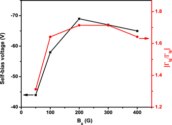
Figure 3. Dc self-bias voltage (square) and the ratio of the time-averaged ion fluxes  at the grounded electrode and powered electrode(circle) as a function of the magnetic field gradient at the gas pressure of 30 mTorr.
Download figure:
Standard image High-resolution imageTo verified the effect of magnetic field gradient on ion kinetics, IEDFs is analyzed. Figures 4(a) and (b) show the IEDFs at the powered electrode and the grounded electrode as a function of the Bg when the Bp keeps constant of 10 G, respectively. At the powered electrode, the maximum of ion bombarding energy increases first and then decreases as the magnetic field strength Bg increases, this is consistent with the trend of self-bias profile. Besides, the relative number of high energy ions increases with a consequent decrease in the number of low energy ions. At the grounded electrode, the maximum of ion energy decreases as the magnetic field strength Bg increases. This is probably caused by an increase of the local ion density and a shorter sheath width at constant voltage. The maximum ion energy changes by a factor of 1.2 at the powered electrode, while changes by a factor of 3.7 at the grounded electrode.

Figure 4. Ion energy distribution functions (IEDFs) at the powered electrode (a) and the grounded electrode (b) as a function of the magnetic field gradient at the gas pressure of 30 mTorr.
Download figure:
Standard image High-resolution image3.2. Gas pressure
Then, we studied the effects of gas pressure on plasma characteristics. Figure 5(a) shows the time-averaged ion flux  profile for different gas pressure at the magnetic field gradient of 10–50 G. The ion flux decreases with the gas pressure at both electrodes. When the gas pressure is as low as 30 mTorr, the ion flux asymmetry can be clearly observed, due to the influence of asymmetric magnetic field. When the gas pressure is increasing, the ion flux asymmetry gradually disappears. Figure 5(b) shows the time-averaged ionization profile for different gas pressure. It can be seen that ionization occurs at both sheath edge and two ionization peaks occur. When the gas pressure is low, the difference between two ionization peaks is large, so the asymmetric plasma response is obvious. When the gas pressure exceeds 200 mTorr, the ionization becomes to symmetry. This is due to the fact that, under these circumstances, the frequent electron-neutral collisions can disrupt electron gyromotion and thus the MAE is greatly reduced.
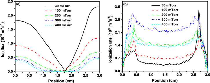
Figure 5. Time-averaged ion flux  profiles as a function of gas pressure at the magnetic field gradient of 10–50 G.
Download figure:
Standard image High-resolution imageThe black line with square in figure 6 shows the self-bias voltage as a function of gas pressure at the magnetic field gradient of 10–50 G and the red line with circle shows the ratio of the time-averaged ion fluxes  at the grounded electrode and powered electrode. The self-bias voltage decreases monotonically with the gas pressure. This is due to the fact that a higher gas pressure leads to a more resistive discharge and thus leads to a stronger voltage drop across the plasma bulk at distinct times within one rf period. According to the analytical model of Czarnetzki et al [42], it will result in a decrease of the dc self-bias voltage. A similar situation, i.e. the effect of a high bulk voltage on the EAE, was investigated by this extended model [43]. If the gas pressure continues to increase, the self-bias voltage may be smaller and smaller until disappear. The trend of the ratio
  is consistent with the trend of self-bias voltage.
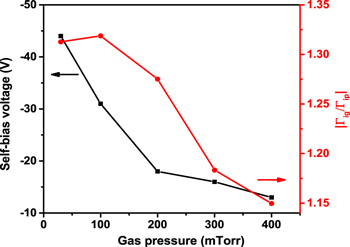
Figure 6. Dc self-bias voltage(square) and the ratio of the time-averaged ion fluxes  at the grounded electrode and powered electrode(circle) as a function of gas pressure at the magnetic field gradient of 10–50 G.
Download figure:
Standard image High-resolution imageFigures 7(a) and (b) show the IEDFs at the powered electrode and the grounded electrode as a function of gas pressure at the magnetic field gradient of 10–50 G, respectively. The maximum of ion bombarding energy decreases with the gas pressure at both electrodes, this is consistent with the trend of self-bias profile. By comparing with the IEDF profiles at both electrodes, we can obtain that, when the gas pressure is low, the maximum of ion energy at powered electrode is larger than the maximum at the grounded electrode. This is the result of MAE. When the gas pressure exceeds 200 mTorr, the shape and width of IEDFs are the same, indicating that asymmetric plasma response is disappeared.
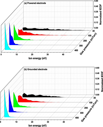
Figure 7. IEDFs at the powered electrode (a) and the grounded electrode (b) as a function of gas pressure at the magnetic field gradient of 10–50 G.
Download figure:
Standard image High-resolution image3.3. Gap length
We also study the effects of changing gap length on plasma characteristics. In figure 8, the black line with square shows the self-bias voltage as a function of gap length at the gas pressure of 30 mTorr and the magnetic field gradient of 10–100 G. The red line with circle shows the ratio of the time-averaged ion fluxes  at the grounded electrode and powered electrode. The self-bias voltage increases with the gap length until 8 cm when saturated. The value can be as high as 70 V, which is 47% of the applied voltage amplitude. The trend of IEDFs are similar to the cases of magnetic field gradient, so the IEDF profiles are not shown here.

Figure 8. Dc self-bias voltage(square) and the ratio of the time-averaged ion fluxes  at the grounded electrode and powered electrode(circle) as a function of gap length.
Download figure:
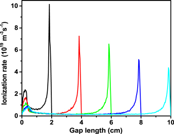
Standard image High-resolution imageFigure 9 shows the time-averaged ionization rate profiles as a function of gap length. From the figure, we can see that ionization mainly occurs at both sheath edge. Two ionization peaks are clearly obsearved, in which the one near the grounded electrode is much higher than the one near the powered electrode. With the increase of the gap length, the ionization is decreased at both plasma bulk and sheath. The larger difference between two ionization peaks will result in unequal ion flux between two electrodes, thus producing a larger self-bias voltage.
Figure 9. Time-averaged ionization rate profiles as a function of gap length.
Download figure:
Standard image High-resolution image
4. Conclusion
In this work, we studied the effect of magnetic field gradient on plasma characteristics at gas pressure of 30 mTorr, when the magnetic field strength Bg changing from 50 to 400 G while Bp keeps constant of 10 G. It found that the ion flux at two electrodes are not equal due to the magnetic field gradient, resulting in a self-bias voltage generated. The self-bias grows first and then decreases as the magnetic field gradient increases, with a maximum occurs at 200 G. By appropriately increasing the magnetic field gradient, the self-bias voltage will be increased, which can be used as the effective approach to control the ion bombarding energy at the electrodes since the ion energy is determined by the voltage drop across the sheath.
We also studied the effect of gas pressure on plasma characteristics at the magnetic field gradient of 10–50 G, when the gas pressure changing from 30 to 400 mTorr. It found that the self-bias decreases monotonically with the gas pressure. The ion flux and IEDF profiles show that the asymmetric plasma response will disappear when gas pressure exceeds 200 mTorr, due to the frequent electron-neutral collisions can disrupt electron gyromotion and thus the MAE is greatly reduced.
Finally, we studied the effect of gap length on plasma characteristics at the gas pressure of 30 mTorr and the magnetic field gradient of 10–100 G, when the gap length changing from 2 cm to 10 cm. It found that the self-bias voltage increases with the gap length until 8 cm when saturated. In short, by adjusting the magnetic field gradient, gas pressure and gap length, the range of self-bias voltage can be controlled, thus the flexible adjustment of ion bombarding energy at the electrode can be realized.
Acknowledgments
This work was supported by the National Natural Science Foundation of China (11775090, 11775164). Shali Yang is supported by the China Scholarship Council.