Abstract
This paper presents the design, analysis and realization of a zero stiffness twist morphing wind turbine blade. The morphing blade is designed to actively twist as a means of alleviating the gust loads which reduce the fatigue life of wind turbine blades. The morphing structure exploits an elastic strain energy balance within the blade to enable large twisting deformations with modest actuation requirements. While twist is introduced using the warping of the blade skin, internal pre-stressed members ensure that a constant strain energy balance is achieved throughout the deformation, resulting in a zero torsional stiffness structure. The torsional stability of the morphing blade is characterized by analysing the elastic strain energy in the device. Analytical models of the skin, the pre-stressed components and the complete blade are compared to their respective finite element models as well as experimental results. The load alleviation potential of the adaptive structure is quantified using a two-dimensional steady flow aerodynamic model which is experimentally validated with wind tunnel measurements.
Export citation and abstract BibTeX RIS
1. Introduction
There is a constant drive in the wind turbine industry to increase the blade length of new wind turbine designs in order to reduce the cost of wind energy further. This results in greater load fluctuations, especially at the blade root, as the area swept by the rotor is exposed to greater spatial discrepancies in the wind field. While aerodynamic loads can be significantly reduced by controlling the pitch of each blade individually [1], increased blade inertia results in large amounts of energy required to pitch the blade and an increased time-lag in the response to sudden wind fluctuations. Recent research [2–5] shows significant load reduction by actively adapting the blade profile at any span-wise location in response to the wind environment. These so-called 'smart rotor controls' are often active surfaces distributed along the blade, controlled by measured parameters, which are able to locally adjust the blade profile and reduce the fluctuating aerodynamic loads in real time. Focus has been mainly given to adaptive trailing edge devices due to their reduced mass and complexity, low aeroacoustic noise and low drag compared to conventional mechanical flaps [2, 6–11]. However, other solutions exist for load mitigation, as revealed by several review articles on the applications of morphing structures to wind turbines; these include span-wise, chord-wise and twist morphing [12–14]. As an illustration, an aerofoil shaped twisting structure was presented by Schultz in [15]. The device was constructed by assembling two bistable, rectangular, shallow shells with their concave surfaces facing towards each other. Application of an opposite twisting moment at the short edges snapped the structure from one stable twisted configuration to the other with a maximum twist of ±5°. The twist of shallow shells has also been the focus of intense research by Guest, Pellegrino and co-workers. They presented several detailed analyses related to the inextensional deformation of thin isotropic and orthotropic cylindrical shells [16–18]. Pre-stressed and stress free shells were investigated. In a special case, the shell was manufactured with zero torsional stiffness [19].
This paper describes the development of a novel twist morphing aerofoil with zero torsional stiffness for a range of angles of twist lying between −5° and +5°. The device is designed for use on a wind turbine blade as an aerodynamic control device by enabling a localized variation in the angle of attack of the blade, as illustrated in figure 1. The structure is presented as a tip device to take advantage of the greater lever arm provided and the reduced internal bending moment acting on the morphing section itself. It is worth noting that the primary focus of this research is the structural and static aerodynamic performance of the morphing blade, not the method of actuation.
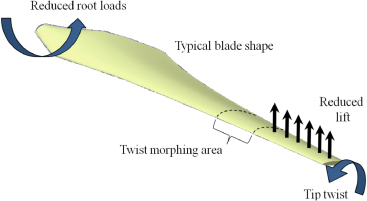
Figure 1. Concept for a twist morphing blade tip for wind turbine load alleviation purposes.
Download figure:
Standard image High-resolution imageIn conventional structures, twist is achieved either by using powerful actuators in high stiffness structures or by designing flexible structures which are easier to deform. As shown by the shape adaptation diagram by Campanile [20], the first solution involves heavy actuators and large energy requirements, while the latter solution leads to unwanted deformations (examples of which are flutter and divergence in aerospace engineering). The purpose of this study is to design a blade section with a large twist deformation capability and high load carrying properties with reduced actuation cost. The torsional stiffness of the blade section is lowered by using a twist-warping mechanism and draws upon works by Vos et al and Mistry et al [21, 22]. We further reduce the actuation requirements with the introduction of a pre-stressed internal structure, as proposed by Lachenal et al and illustrated in figure 2 [23]. The objective is to minimize the variation of strain energy of the structure during twist. Ideally, a constant strain energy level is sought for any loading condition, yielding a zero stiffness structure; hence actuation power is reduced to zero. Symmetric aerofoil sections are ideally suited to this scenario since they have a fixed aerodynamic centre at the quarter chord position for a wide variety of aerodynamic conditions, as demonstrated by Daynes et al in [24]. However, as we base this research on a generic 90 m diameter wind turbine an un-symmetric aerofoil section is chosen with a NACA 63-415 profile. Unlike symmetric aerofoil sections, the resultant aerodynamic moment is a function of the air speed and local angle of attack. It is therefore not possible to achieve zero torsional stiffness for all aerodynamic load cases. Consequently, the aerodynamic forces applied to the morphing blade are not considered and so the focus of this study is on the torsional stiffness of the blade only. To simplify the manufacture of the proof-of-concept, a prismatic blade geometry is designed instead of the complex three-dimensional geometry of typical wind turbine blades. The demonstrator manufactured has a chord c = 0.49 m and a morphing section of span Lm = 0.56 m. A rigid tip is also mounted at the twisting end of the morphing blade to simulate the tip of the wind turbine blade, adding another 0.3 m in length. Wind tunnel tests are carried out to highlight the load reduction potential of the twist morphing blade on the root bending moment.

Figure 2. (a) Three-dimensional model of the morphing blade. (b) Twist morphing blade in the straight configuration without the skin, revealing pre-stressed flanges, bearings, actuation rod and skin holders (two out of four shown for clarity). (c) Twist-warping principle: a rotation of the actuation rod (arrow no 1) produces a relative displacement between the upper and lower skin (arrows no 2), yielding the twist of the morphing section (arrow no 3).
Download figure:
Standard image High-resolution imageThis paper is organized as follows. Details of the design and manufacture of the demonstrator are provided in section 2. The analytical model for the twist morphing blade structure is given in section 3. Predictions of the aerodynamic properties are presented in section 4. The finite element model (FEM) of the demonstrator is described in section 5. The experimental set-up is presented in section 6. Finally, results and concluding remarks are given in section 7.
2. The twist morphing blade concept
2.1. Design
The morphing blade is made of three main components: a skin, a pre-stressed internal structure and an actuation system. These three components all pivot around a cylindrical spar, as shown in figures 2(a)–(c). The skin both provides the means of actuation and acts as an aerodynamic fairing for the internal structure. Actuation is achieved by warping the aerofoil section. This solution, however, requires a discontinuity in the external skin along the length of the trailing edge to allow the pressure and suction sides of the blade to slide relative to each other. This relative motion is made possible by using four sliding bars (skin holders in figure 2(b)) which join the skin to the ribs. These bars have ball-joints attached at their ends to ensure that the ribs can freely rotate about the central spar, see figure 2(b). A side view of the internal structure showing the skin holders and ball-joints is also given in figure 6(a).
The actuation mechanism, introducing the span-wise displacement of the two sides of the trailing edge, needs to be non-reversible, easy to manufacture and low cost. Moreover, the torsional stiffness of the adaptive skin must be equal to the stiffness of the equivalent closed aerofoil section when the structure is static. In other words, the shear flow resulting from the application of a twist moment must travel through the actuation system. A simple lead-screw system is used here for its simple construction and intrinsic non-reversibility. The system is made of a rod comprising two screws with opposing threads joined end to end. Each screw has a threaded bracket fixed to either the suction or the pressure side of the skin, see figure 2(c). When the rod is actuated (arrow no 1 in figure 2(c)) the brackets travel along the lead-screws in opposite directions, yielding a relative span-wise displacement between the upper and lower sides of the trailing edge, as illustrated by arrows no 2 in figure 2(c). The warping of the skin cross-section is associated with the twist of the structure (arrow no 3), resulting in the configuration shown in light grey in figure 2(c). Note that as the morphing section twists the distance between the end points of the actuation rod increases; thus one end of the rod is pinned whereas the other is allowed to translate, as detailed in figure 2(b).
A pre-stressed structure is employed to achieve the zero torsional stiffness: as the morphing blade twists, strain energy is released by the pre-stressed members, thus balancing the elastic energy required by the skin to warp. This results in a reduced torsional stiffness for a wide range of twist angles, as demonstrated in section 3. The internal structure comprises two pre-stressed flanges held at a constant distance R = 88.5 mm from the axis of twist of the blade, as illustrated in figures 2(a) and (b). Pre-stress is achieved by flattening the originally curved parts and restraining them in this heightened state of elastic strain energy. The flanges are linked to the fixed and pivoting ribs using ball-bearings to reduce the amount of energy lost as friction. In total, three bearings per flange are used; see figure 2(b). For the same reason, a needle bearing is mounted between the pivoting rib and the cylindrical spar.
2.2. Manufacture
The skin was manufactured in two halves with the trailing edge joining the two parts. Using a wet lay-up technique, eight layers of woven balanced plain weave glass (290 gsm) were impregnated with an epoxy resin system [25] curing at low temperature and laid on a polystyrene male mould, totalling a thickness of 1.2 mm. A smooth surface was achieved by covering the laminate with release film, see figures 3(a) and (b). The direction of the cloth warp was aligned with the xm-axis. Once trimmed, separated and cut to dimensions, miniature holders were bonded inside the upper and lower sides of the skin; finally, the two halves were held in position and joined at the leading edge with an additional four layers of dry woven glass fibre impregnated with the same epoxy resin system, see figure 3(c).
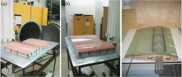
Figure 3. (a) Mould preparation, (b) wet lay-up for the manufacture of the blade skin and (c) bonding of the two halves at the leading edge.
Download figure:
Standard image High-resolution imageThe pre-stressed composite flanges were manufactured on a cylindrical mould of radius Ri = 177 mm; the details of the calculations and lay-up specifications are provided in section 3. A computer numerical control (CNC) ply cutter was used to cut each ply of 8552/IM7 unidirectional (UD) carbon fibre reinforced plastic (CFRP) from Hexcel® [26]. The ply cutter was also used to cut the holes required to install the ball-bearings attaching the flanges to the ribs, avoiding drilling and the associated fibre delamination at a later stage. Figure 4(b) shows the set of two flanges wrapped around the cylindrical mould. The holes are filled with cork to avoid the resin flowing into the cavities during the high temperature cure cycle. Because of the cylindrical shape of the laminate, the length of each ply was tailored to achieve alignment of the holes through the thickness of the parts. Furthermore, to avoid cutting the cured parts, the plies were cut to size and laid next to each other on the mould, as shown in figure 4(b). The cured flanges were then separated by simply initiating a crack between them, which resulted in clean, sharp, edges. The holes were reinforced with UD reinforcements on the top and bottom surfaces of the laminate to inhibit cracks and delamination occurring in these regions.

Figure 4. (a) Lay-up of the flanges over a cylindrical mould. (b) A CNC ply cutter was used which enabled the bearing holes to be precisely cut. (c) Detail of the local 90° UD reinforcements to be added around the holes.
Download figure:
Standard image High-resolution image2.3. Assembly
The flanges were first mounted onto the spar in a coiled configuration. They were then extended to the straight equilibria prior to the ribs being installed, see figure 5(b). The skin was then fitted over the structure and held by the skin holders, as shown in figure 5(c). Finally, the actuation rod was added and the rigid tip was mounted for wind tunnel testing (figure 5(d)).

Figure 5. (a) Assembly starts with mounting the ball-bearings onto the flanges; (b) the flanges are attached to the spar, then straightened, and the ribs are installed; (c) the skin is fitted with the skin holders; (d) the actuation rod is added and the rigid tip is mounted.
Download figure:
Standard image High-resolution image3. Analytical model
In a conventional structure with a linear elastic response, strain energy arises with deformation, resulting in a reaction force. However, when engineering a zero stiffness device the strain energy level must remain constant with regard to the direction of the externally applied load or moment. In this work we achieve a constant strain energy level by balancing the elastic strain energy resulting from the skin's twist with the pre-stress applied to the flanges of the internal structure. The following sections detail the analytical model of each component and their integration to achieve zero torsional stiffness.
3.1. Warping skin
As with any adaptive structure, the morphing blade must meet conflicting requirements: here the blade needs to be compliant in torsion under actuation and stiff to withstand external loading. This trade-off is achieved by using the warping mechanism of an open shell section in a controlled manner, as detailed by Vos et al [21]. A simplified approach to this principle is first described with the example of a hollow tube under pure torsion. The closed section of the tube provides a high torsional stiffness. If a slit is made along the length of the tube, then the torsional stiffness is greatly reduced. As a consequence, twisting is easily achieved; however, the load carrying capability is significantly diminished. The twist of the tube is also associated with warping of the cross-section [27]: the two sides of the slit slide in opposite directions and the cross-section rotates about the shear centre of the tube. Application of the reverse of the above principle is true: a relative displacement imposed between the two sides of the slit induces warping of the cross-section and large amounts of twist can be achieved. The load carrying capability of the tube depends therefore on the actuation mechanism: with the two sides of the slit being connected, the section can be considered as closed, with the stiffness effectively equal to the torsional stiffness of the original tube. Here, one can imagine the tube to be the blade section, where the slit is made at the trailing edge.
The strain energy of the skin can be expressed as [27]
where Lm is the morphing blade span, the angle of twist ϕ is shown in figure 6(a) and Mx is the twist moment applied to the skin, defined as
Because the skin is pinned at its root on the leading edge and free to warp in the xm-axis (see figure 2(a)), the rate of twist dϕ/dx is assumed constant over the length Lm of the demonstrator. Furthermore, Γ is the torsional stiffness of the open cross-section skin and is given by [28]
Here, δ66 is the (3, 3) term of the bending compliance matrix of the skin [28] and bskin is the circumference of the skin section. Substitution of (2) and (3) into (1) yields
It is convenient to express the angle of twist ϕ (see figure 6(a)) as a function of the angle between the pre-stressed flanges and the xm-axis of twist, called the angle of helix θ (figure 6(b)) and given as [23]

where R is the perpendicular distance between the flanges and the axis of twist of the blade, as illustrated in figure 6(a). Substitution of (5) into (4) yields


Figure 6. (a) Side view of the blade showing the angle of twist ϕ between the root rib (dark grey) and the tip rib (light grey). (b) Front view of the morphing blade section in a twisted configuration. Transparency was applied to the skin to show the angle of helix θ between the axis of twist xm and the local x-axis of the flange.
Download figure:
Standard image High-resolution imageWhen twist occurs, the skin holders are also subjected to bending deformations; thus their contribution to the total strain energy needs to be accounted for. The skin holders are free to translate and rotate about their longitudinal xm-axis; therefore their deformations are assumed inextensional and include bending strain energy only. With the flexural stiffness of the skin holders expressed as EI in the xm-direction, the strain energy of each skin holder of length Lm is

where E is the Young modulus of the skin holders of diameter d and I is the second moment of area of the circular section, given by  . Δκbar−x is the (1, 1) component of the tensor change of curvature of the skin holders given by [29]
where Rbar is the perpendicular distance between the skin holders and the axis of twist of the helix (see figure 6).
The strain energy for the aerofoil comprising the skin and the four holders is thus given by
The resultant twist moment of the aerofoil is found by applying Castigliano theorem to the aerofoil in torsion, yielding

3.2. Pre-stressed internal structure
The internal structure of the morphing blade is similar to the device by Lachenal et al: two pre-stressed flanges are kept at a constant distance 2R from each other and allowed to adopt a twisted shape when subject to a twist moment about the xm-axis [23]. The pre-stress of the flanges results from the flattening of the originally curved parts of radius Ri. Note that although the morphing blade is designed to twist between ϕ =± 10°, the pre-stressed internal structure is not limited to this range of twist angles and can take any twisted shape between a coiled and a straight configuration; hence the analytical model is given for the entire twist morphing spectrum, i.e. −360° ≤ ϕ < 360°. From (5), this corresponds to 0° < θ < 90°.
As in [23], we assume that the flanges deform uniformly and the deformations are purely inextensional. The assumption of inextensional deformations is valid for thin shells where the strain energy associated with stretching is much larger than the strain energy associated with bending and twisting [30]; thus the strain energy includes only bending energy and is given by [28]

where D* = BA−1B is the reduced bending stiffness matrix, with A,B and D the in-plane, bending–extension coupling and flexural stiffness matrices respectively as defined in classic lamination theory [31]. The terms Lm,w and n are the length, width and number of flanges respectively. Finally, ΔκT is the transpose of the tensor describing the change of curvature of the flange in its respective (x,y) coordinate system, where the x-axis is parallel to the long edge of the part (see figure 6(b)). It is worth noting that because of the construction of the internal structure, only x- and xy-changes of curvature can be generated, whereas changes of curvature about the y-axis (transverse curvature) cannot be imposed on the flanges. Instead, we assume that the transverse curvature is constant over w and is found by satisfying the equation of moments about the y-axis considering the free edge boundary condition of the flanges, yielding
Because the flanges are kept at a constant distance R throughout the transformation, the flanges are assumed to lie tangent to a virtual cylinder of radius R. Hence, Δκx and Δκxy can be found by using a Mohr's circle of curvature change as in [23, 29], yielding


The non-dimensional ratio α = Ri/R is introduced to capture the influence of the manufactured radius Ri on the stability of the structure [23].
From (12) to (14), the change of curvature to any configuration of a flange can be described by the tensor Δκ in the (x,y) coordinate system as
Substitution of (15) into (11) yields
Using Castigliano theorem, the axial force required to deform the internal structure can be found. This is particularly important for modelling of the force–displacement characteristic of the internal structure for comparison with the experimental results. With F being the resultant axial force and ΔL the displacement of one end of the structure, the following relationship holds:

Similarly to the axial force, the resultant twist moment of the internal structure is given by (using Castigliano theorem)
3.3. Zero torsional stiffness design
We purposely design the morphing blade with zero torsional stiffness for angles of twist ϕ lying between −5° and +5°. This is analytically modelled by

Ublade is the total strain energy of the morphing blade, comprising the strain energy of the internal structure and the aerofoil

While the strain energy Uaerofoil is hardly tailorable, the strain energy Uflange is highly tailorable (equation (16)): the geometry (through the ratio α) and the terms of the D* matrix (through the lay-up of the flanges) can be tailored to achieve the overall zero torsional stiffness. To limit the design space of the flanges, the ratio α has a set value of one. Furthermore, the lay-up can be simplified by noting that the resultant twist moment of the skin is zero at ϕ = 0. Indeed, it was shown in [23] that off-axis fibres in the symmetric lay-up of the flanges yield a resultant twist moment in the straight configuration of the internal structure; hence the lay-up of the present flanges is limited to [0p], where the subscript p denotes the number of plies. The optimum number of plies is found by plotting equation (19) (i.e. blade twist moment and torsional stiffness) as a function of ϕ and p in the lay-up [0p]. Figures 7(a) and (b) show that the optimum number of plies satisfying equation (19) is p = 9, yielding the lay-up [09]. Although this is not an exact solution as the twist moment and torsional stiffness are not constant for the range of twist angle desired, this is the best compromise for the present application. From experience, a 90° layer is inserted in the middle plane of the laminate to avoid delamination, resulting in the lay-up [04/90/04]. The effect of this change on the bending stiffness of the flange is small due to the central position of the 90° ply within the laminate.
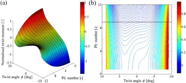
Figure 7. (a) Surface plot of the twist moment of the morphing blade as a function of the angle of twist ϕ and the number of plies p in a lay-up [0p]. (b) Contour plot of the normalized torsional stiffness of the morphing blade. The dotted line shows the optimum number of plies p = 9.
Download figure:
Standard image High-resolution image4. Two-dimensional, inviscid, steady flow wind tunnel model
A wind tunnel model was developed to predict the load alleviation properties; hence the geometry is identical to the physical prototype. The morphing section with a NACA 63-415 aerofoil profile and a chord length c is able to twist by an angle ϕ over the length Lm. A rigid tip of the same aerofoil profile is mounted at the twisting end of the morphing section and has a length Lt and chord length c. Figure 8 shows the angle of incidence of the model αR and the free-stream of velocity V, assumed to flow around the demonstrator in a two-dimensional steady state flow as per blade element theory [32]. Thus any velocity components of the flow in the span-wise direction are assumed negligible, as too are three-dimensional effects. As we are not concerned with the effect of the boundary layer, we also assume the flow to be inviscid. This allows us to build a simple model predicting the evolution of the root bending moment MY and the lift coefficient of the demonstrator Cl.
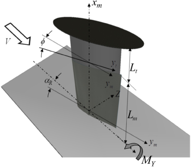
Figure 8. Schematic view of the wind tunnel test set-up.
Download figure:
Standard image High-resolution image4.1. Span-wise root bending moment
As with wind turbines, the load alleviation is quantified by the span-wise root bending moment MY. This is expressed as a piecewise integral over the total span of the demonstrator as

where ℓα,m is the section lift produced over the morphing blade section and ℓα,t is the section lift produced over the tip section of the demonstrator; xm is the distance between the section of integration and the blade root. From basic aerodynamics, the section lifts are given as [33]


where ρ is the air density, V is the free-stream air speed, c is the aerofoil chord length and cl,m and cl,t are the section lift coefficients of the morphing blade and the rigid tip respectively.
Within the morphing blade, the section lift coefficient can be computed as a linear function of the section lift-curve clα, the root angle of attack αR in radians, the zero-lift angle of the aerofoil section α0l, the angle of twist ϕ and the position xm from the root [21],

As the aerofoil profile is assumed identical between the rigid tip and the morphing area, (24) simplifies for the rigid tip to

Substituting (24) and (25) into (22) and (23) respectively then proceeding with the integration of (21) yields the expression of MY,
where clα and α0l are intrinsic aerodynamic properties of the aerofoil section and are given by the aerodynamic panel code software X-Foil [34].
4.2. Coefficient of lift
From an aerodynamic perspective, it is interesting to know the evolution of the coefficient of lift of the entire demonstrator. This is given as a function of the lift-curve of the demonstrator Clα, the twist angle ϕ and the zero-lift twist angle of the blade ϕ0l,

where, from [33], the lift-curve of the blade is

From [33], the value of f is equal to unity. Furthermore, the effective lift-curve ae is given as a function of the section lift-curve clα and the Jones edge-velocity factor J as per [33]

Here, J is equal to the ratio of the semi-perimeter of the aerofoil section to the length of the blade [33], yielding J = 0.56 for the demonstrator.
In (27), the angle of twist ϕ0l can be found by setting the expression for the total lift of the blade Lblade to zero at the particular ϕ0l angle,
From (22) and (23), equation (30) yields

Hence, the coefficient of lift of the demonstrator is given by
5. Finite element modelling
An FEM of the morphing blade was developed using ABAQUS® Standard [35] to validate the analytical model given by equation (19). The morphing blade was modelled with two separate analyses. Once straightened in a first analysis, the pre-stressed flanges were inserted into the skin along with the mechanical linkages in a second analysis. Both analyses used a Newton–Raphson iterative process. Due to the low mass of the flanges and the slow motions involved in the studies, the velocity and acceleration terms were neglected. Non-linear geometric effects were taken into account for each step in both analyses. The rigid tip, the cylindrical spar and the actuation mechanism were not included in the FEM to limit the complexity of the model and reduce the computation time; instead the 'connector' tool in ABAQUS was used to model the pivot provided by the cylindrical spar and opposite axial displacements were applied as boundary conditions to the trailing edge to model the actuation mechanism.
5.1. First analysis: pre-stress of the flanges
Both flanges were modelled with four node shell elements (S4R). A 10 × 111 element structured mesh was used as it yielded an acceptable compromise between model fidelity and computation time. The flanges were modelled with an initial curvature κx = 1/Ri = 1/88.5 mm−1. Reference points (RPs) were added to the geometry in order to ease the flattening operation and the construction of the connectors in the second analysis. Five RPs were positioned in the (x,z) plane at a distance equal to R = 88.5 mm from the flange, on the concave side and along a radius of the part. The RPs were then locally tied to the flange using rigid body constraints. As per the demonstrator, flattening of the part was achieved by applying displacement boundary conditions to the RPs. It is worth noting that the initial geometry of the flanges was approximated as a circular shape; thus the local span-wise flattening resulting from mounting the ball-bearings was not modelled. The relevant material properties of the UD CFRP employed for the flanges are given in table 1.
5.2. Second analysis: assembly and twist
In the second analysis, the deformed meshes of the pre-stressed flanges were first imported. Connectors were inserted to restrain the necessary degrees of freedom of the flanges, as shown in figure 9. Hinges were used to model the ball-bearings and cylindrical connectors were employed in place of the spar. The skin was modelled using a structured mesh of 70 × 36 four node shell elements (S4R). The mesh was refined around the leading edge due to the tight radii in this region of the shell. Material properties of the woven glass fibre reinforced plastic (GFRP) used for the skin can be found in table 1. 'Ball-joint' connectors were created and used to link the skin to the flanges in a similar way to the manufactured demonstrator. This kind of connector offers one translational and three rotational degrees of freedom. Moreover, the skin was pinned at its root, on the leading edge, to suppress the xm-direction translational degree of freedom. Additional ball-joint connectors were inserted at the trailing edge to model the restraints from the actuation rod. Finally, a contact constraint was added between the suction and pressure sides at the trailing edge. Span-wise displacement boundary conditions were applied to the skin trailing edge at the locations of the travelling brackets of the demonstrator to induce twist.
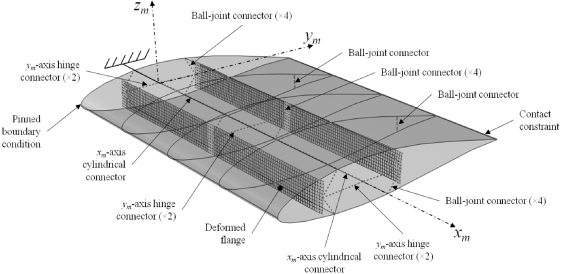
Figure 9. Initial geometry of the second analysis, showing the flattened flanges and the several connectors linking the skin to the flanges.
Download figure:
Standard image High-resolution image6. Test set-up and results
6.1. Static tests
The internal structure of the blade prototype was first tested to verify the accuracy of the analytical model given by equation (17). A force–displacement graph was produced by stretching the structure from the coiled to the straight configuration, as illustrated by figures 10(a) and (b). A fixture, allowing one end of the device to freely twist, was designed for the test. The results were compared to the analytical curve and the data produced by the FEM of the internal structure. Quantitative agreement was found between the three curves, as illustrated in figure 10(c). Interestingly, a dip in the force–displacement curve appears at θ ≈ 20° for both the FEM and the experimental curve; however, the analytical model fails to reproduce this evolution. This can be explained by the simplified model for the deformations of the flanges in the analytical model, especially the assumption of constant transverse curvature.

Figure 10. (a), (b) Force–displacement test of the internal structure. (c) Plot of the axial force against the angle of helix for the same structure.
Download figure:
Standard image High-resolution imageThe analytical model of the skin was verified by testing the aerofoil in torsion. For this, the skin and skin holders were assembled onto the cylindrical spar without the flanges. The rotation was imposed on the skin by creating a vertical displacement h at a distance r from the axis of twist, see figures 11(a) and (b). The cross head of a tensile test machine was used for this experiment, thus the force Fr required to twist the skin was monitored as well. We ignored the lateral displacement resulting from the rotation of the lever arm due to the small angle of twist. We also assumed the lateral component of the force yielded by this lateral displacement to be small. From figure 11(b), the displacement of the cross head is related to the twist angle by
The twist moment is simply

Combining equations (33) and (34) yields the experimental moment–twist curve of the skin shown in figure 12(b). It is worth noting that the FEM, analytical and experimental curves are in agreement for small angles of twist, of the order of −5° < ϕ <+ 5°. Large differences are noted for larger angles. A preliminary study was therefore carried out to verify the validity of the skin analytical model given by equation (6) using a simple slit cylindrical tube under warping. As seen in figure 12(a), the strain energies given by equation (6) and given by the FEM of the slit tube are in near perfect agreement. We can therefore conclude that the aerofoil section warps, but the boundary conditions applied to the skin also restrain it, resulting in local stretching and bending of the material with an overall change of the aerofoil shape, as was noticed in [21, 22]. Consequently, the moment required to twist the skin drastically increases, whereas equation (6) predicts a linear evolution of Mx, as illustrated in figure 12(b).
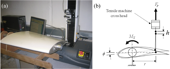
Figure 11. (a) Test of the skin's resultant twist moment. (b) Schematic of the test kinematics.
Download figure:
Standard image High-resolution image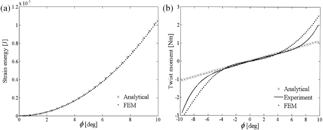
Figure 12. (a) The analytical model and FEM are in near perfect agreement on the strain energy evolution of a slit tube under warping with a resulting twist of ∼10°. (b) Twist moment of the aerofoil skin. The restraints added by the boundary conditions of the demonstrator are not captured by the analytical model, hence the mismatch between the curves. The FEM and experimental data are considered to be in agreement.
Download figure:
Standard image High-resolution imageOnce assembled, the morphing blade was tested in torsion to validate the analytical model given by equation (19). The same test as described in the previous paragraph was realized. It is worth noting that the moment created by the weight of the morphing section was subtracted from the result, as the blade is meant to work in a vertical plane. Figure 13 superposes the results yielded by the analytical models of the skin (crosses), the flanges (dashed line) and the assembled blade (dot–dash line) in order to visualize the influence of each component on the final twist moment. The experimental twist moment from the torsion test of the blade (continuous line) and the result from the FEM (dotted line) are also plotted for comparison. Close agreement is found between the curves for −5° < ϕ <+ 5°, yielding a near zero torsional morphing blade for this range of twist angles. As explained previously, the analytical model fails to capture the complex deformations of the skin under warping; hence large differences are found for larger twist angles. The FEM, on the other hand, is able to accurately describe the behaviour of the skin subject to large deformations.
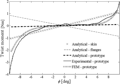
Figure 13. Plot of the twist moment from the analytical models of the skin, the flanges and the morphing blade. The experimental data from the test of the blade in torsion as well as the result from the FEM are also shown.
Download figure:
Standard image High-resolution image6.2. Kinematics
From a kinematic perspective, the angle of twist resulting from the relative displacement Δw between the trailing edge's upper and lower skin is given by [27]
where A is the area of the aerofoil cross-section. The kinematic model of the actuation system given by equation (35) was verified with a bench test, as shown in figures 14(a) and (b). The angle was measured with a digital protractor for each turn of the actuation rod. Agreement was found between the mathematical model and experiment, as seen in figure 14(c).
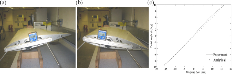
Figure 14. Measurement of the angle of twist of the blade resulting from warping of the skin. The demonstrator is seen in the two extreme configurations of (a) −10° and (b) +10° of twist. (c) Evolution of the angle of twist ϕ as a function of the warping displacement Δw given by the analytical model and the experiment.
Download figure:
Standard image High-resolution image6.3. Wind tunnel tests
The aerodynamic model presented in section 4 was verified with a series of wind tunnel tests at the University of Bristol's 6' × 5' wind tunnel. The objective of the tests was to demonstrate the influence of the morphing section on the bending moment at the root of the blade and on the overall coefficient of lift of the demonstrator. Actual bending moments and total forces were measured using an external OR6-7 2000 series force platform manufactured by AMTI [37]. The demonstrator was mounted in a vertical configuration with the cylindrical spar attached to the force balance with a bespoke mounting, providing the rotation about the xm-axis required to adjust the root angle of attack αR. Two series of tests were carried out, at air speeds of V = 12.5 and 25 m s−1. For each air speed, the angle of attack at the blade root αR took the values −5°,0°, + 5° and +10°, and for each root angle αR, the angle of twist ϕ was varied between −10° and +10°. To satisfy the condition of two-dimensional air flow, an elliptical flat plate was mounted onto the rigid tip, as shown in figures 15(a)–(c) and 8.
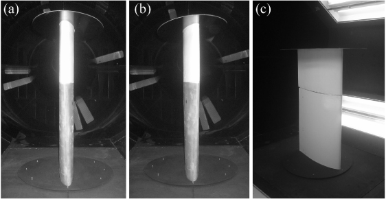
Figure 15. Pictures of the morphing blade inside the wind tunnel with a tip twist of (a) +10° and (b) −10°. (c) Photograph of the completed prototype.
Download figure:
Standard image High-resolution imageCorrection factors were added to the experimental data to account for discrepancies between free-stream flow and the flow behaviour in a closed section wind tunnel, as detailed by Barlow in [38]. Figures 16(a) and (b) show the evolution of the root bending moment as a function of the angle of twist for V = 12.5 m s−1 and V = 25 m s−1 respectively. Agreement is found between the corrected wind tunnel test data and the analytical model given by equation (26), although a deviation from the linear trend is observed for large angles of twist. This is explained by the deformation of the cross-section of the blade under twist, i.e. the aerodynamic model assumes a constant aerofoil section with varying local angle of attack; however, a noticeable change of aerofoil shape was seen at high twist angle.
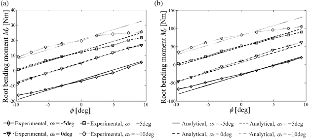
Figure 16. Evolution of the root bending moment for (a) V = 12.5 m s−1 and (b) V = 25 m s−1. The results from the analytical model and the corrected experimental data are shown for a root angle of attack αR =− 5°–+10°.
Download figure:
Standard image High-resolution imageThe analytical model of the coefficient of lift given by equation (32) is compared to the corrected wind tunnel data in figures 17(a) and (b) for the two air speeds. Agreement is found between the two sets of data; however, as previously mentioned, differences can be seen between the curves for large angles of twist. It is worth noting that a maximum change in coefficient of lift of ΔCl = 1.4 was achieved by warping the blade with αR = 0 and V = 25 m s−1.

Figure 17. Evolution of the blade coefficient of lift for (a) V = 12.5 m s−1 and (b) V = 25 m s−1. The results from the analytical model and the corrected experimental data are shown for several root angles of attack αR =− 5°–+10°.
Download figure:
Standard image High-resolution image
7. Conclusion and future work
A twist morphing blade with no torsional stiffness about its axis of twist for angles ϕ lying between −5° and +5° was analytically modelled, validated with finite element software, manufactured and tested. The morphing structure consisted mainly of three components: an aerofoil skin, a pre-stressed structure and an actuation mechanism. The device twisted about a cylindrical spar providing bending stiffness in the span-wise direction. Twist was achieved by warping the skin, allowing large twist deformation yet high torsional stiffness. The internal structure comprised two pre-stressed flanges balancing the strain energy of the skin, yielding the zero torsional stiffness property. Analytical models and FEMs of the skin, internal structure and morphing blade were presented. Agreement was found between the analytical predictions, FEM data and experimental results for −5° < ϕ < 5°; however, large deviations from the analytical model were noticed for wider twist angles due to the simple model used for the blade skin. A series of wind tunnel tests was also carried out to verify the effect of the twist morphing on the overall root bending moment and lift coefficient. Agreement was found with the aerodynamic analytical model for small angles of twist, although correlation between the models was not found for higher twist angles due to the deformation of the aerofoil section, which was not analytically modelled.
Acknowledgment
The authors would like to thank Vestas Wind Systems for funding of this work as part of the 'Morphing composites for wind turbine applications' project, which is gratefully acknowledged.