Abstract
This paper presents the realization of a wearable thermoelectric generator (TEG) in fabric for use in clothing. A TEG was fabricated by dispenser printing of Bi0.5Sb1.5Te3 and Bi2Se0.3Te2.7 in a polymer-based fabric. The prototype consisted of 12 thermocouples connected by conductive thread over an area of 6 × 25 mm2. The device generated a power of 224 nW for a temperature difference of 15 K. When the TEG was used on the human body, the measured output power was 224 nW in an ambient temperature of 5 °C. The power of the TEG was affected by the movement of the wearer. A higher voltage was maintained while walking than in a stationary state. In addition, the device did not deform after it was bent and stretched several times. The prospect of using the TEG in clothing applications was confirmed under realistic conditions.
Export citation and abstract BibTeX RIS
1. Introduction
In recent years, with advances in portable electronic devices and in wireless sensing, the demand for auxiliary battery power and wireless power has rapidly increased. One approach to satisfy this demand is to harvest energy from the activities of people or other lifeforms through a wearable generator. In this way, portable electronic devices can supply themselves with sufficient energy to operate or to extend the available battery time. The most common alternatives are based on photovoltaic and piezoelectric generators [1, 2]. However, in order to use solar energy, the generator should be outdoors during daylight. Further, harvesting of vibration energy can only take place when the wearer of the device is moving. Because of these limitations, we are seeking an alternative energy source.
Since we wish to power devices that are used by, and therefore in proximity to, humans, human body heat represents a convenient, ever-present energy source that will never run out. A thermoelectric generator (TEG) can harvest the wasted body heat through contact with the human body. Since it depends on the Seebeck effect, the power generated by the TEG is proportional to the temperature gradient between the hot and cold junctions. When used with the human body, the skin is the hot junction, and the outside air is the cold junction. The advantages of the TEG are small size, the absence of mechanical moving parts and non-toxicity. For this reason, the TEG is suitable for use with the human body. In harsh environments and in emergency situations, the wearable TEG can be constantly used as an energy source. Further, it has been used to supply power to bio-implant devices or wireless monitoring sensors in patients [3].
Previous work on the application of flexible TEGs to humans has been conducted. Weber et al [4] used a coiled-up polymer foil TEG for human-body applications. Glatz et al [5] presented a combination of copper and nickel in a thick flexible polymer mold fabricated by photolithography. Most flexible TEGs are not sufficiently flexible to withstand the demands placed on them by human activity [6, 7]. The research described above required the complex fabrication of flexible TEGs. For application forms to the human body, there are watch, buckle and shoes forms [8, 9]. However, the coverage area of these forms is limited compared to the total human body area.
A TEG designed for human use should not interfere with the movement of the wearer. For the purposes of being comfortable and providing energy harvesting over a wide surface area, it is suitable to use a TEG in the form of clothing that can be worn. At this point, we propose and demonstrate the wearable TEG, made from a combination of fabric and thermocouples. The thermocouple was made by the dispenser printing method; this technique is an easy and low-cost process. We fabricated a prototype to test the thermal performance of the device while it was being worn by a human subject.
2. Design
2.1. The thermoelectric model on the human body
When the number of the thermocouples is n, the Seebeck coefficient of the used thermoelectric materials is α, and the temperature difference between hot and cold junctions is ΔTTEG ; an output voltage V is generated by the Seebeck effect:

The output power P is dependent on the internal electrical resistance RG and the external load RL :

When RL is equal to the internal electrical resistance RG , which provides optimal impedance matching, the maximum output power P0 is achieved:

The equivalent thermal circuit of the TEG on the skin is depicted in figure 1. The core temperature of the human body is about 36 °C, and the ambient temperature is from −10 to 40 °C, depending on the environment. A TEG is placed in contact with the skin, and another of its surfaces is open to the ambient air. The temperature difference of the TEG (ΔTTEG ), which is defined as the difference between the temperature of the outer surface Tsurface and the temperature of the skin Tskin, can be expressed as follows:


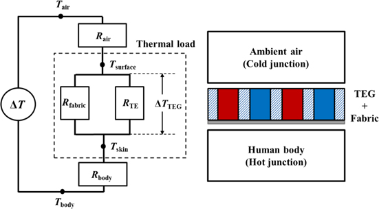
Figure 1. The equivalent thermal circuit model of a TEG on the human body.
Download figure:
Standard image High-resolution imageThe output voltage is proportional to ΔTTEG , as shown in equation (1). The ambient temperature has the greatest effect on the ΔTTEG . The high thermal resistivities of the human skin and of the ambient air affect the total thermal resistance in the thermal circuit. Therefore, the temperature difference across the TEG is significantly lower than the measured temperature difference between the air and the body. Each individual thermocouple has a low thermal resistance; the thermal resistance of a single thermocouple is not large enough to cause a large temperature difference between the surfaces of the TEG. Furthermore, the parallel arrangement of the thermocouples makes the total thermal resistance even smaller [9]. Consequently, even a large temperature difference ΔT will result in a relatively small temperature difference between the hot and cold junctions because the thermal resistance of the TEG RTEG is so small, as can be seen from equation (5). However, environmental changes can cause a more active heat exchange on the surface. The thermal resistance can be reduced by air convection caused by wind or other naturally occurring air currents or by human movement. Thus, the performance of the thermoelectric device can vary depending on the situation.
2.2. Design of the wearable TEG
Figure 2 shows the concept views of the proposed wearable TEG. As shown in the figure, the form of the device allows it to be easily embedded in clothing. Thermoelectric columns of p- and n-type material are located in the polymer-based fabric. Each thermocouple is electrically connected by a conductive fabric fiber. A polyimide film is attached to the bottom of the TEG and prevents physical and electrical contact of the TEG with the skin. The polyimide film was chosen because of its superior thermal and electrical resistance [10].

Figure 2. Concept views of the proposed wearable TEG device. (a) A shirt with the wearable TEG. (b) A schematic of the design of the wearable TEG on the skin.
Download figure:
Standard image High-resolution imageGeometrical details of the prototype are shown in figure 3. The prototype with 12 integrated thermocouples has an area of 6 × 25 mm2. The element radius of the thermocouple has a diameter of 4 mm with a thickness of 0.6 mm, and the spacing between the elements is 4 mm. The attached polyimide film thickness is 100 μm. The geometries of each thermocouple were determined with reference to the optimization design research [11]. However, the arbitrary selected design has not been optimized for area and density. There are restrictions on the design. Increasing the number of thermocouple elements per unit area decreases the flexibility of the device. Thus, sufficient spacing between the elements is required.

Figure 3. Schematic showing a pair of p-n thermocouples and the specific dimensions of the design.
Download figure:
Standard image High-resolution image3. Materials and fabrication technology for the prototype
3.1. Thermoelectric material synthesis
We have previously proposed a flexible TEG using PDMS (polydimethylsiloxane) for human body heat. The device had a good flexibility, but it was not good enough for wearing because of a thick PDMS substrate [12]. In this work, we demonstrate wearable TEG and better performance for low temperature energy harvesting. The thermocouple of the prototype consisted of Bi0.5Sb1.5Te3 (p-type) and Bi2Se0.3Te2.7 (n-type). These powdered materials (325 mesh), purchased from RND Korea Comp., show better thermoelectric properties than the Bi2Te3 used in our previous work [12]. Liquid binder is used to solidify the powders; it is a refractory ceramic colloid in water (Durabond 950, IS-Rayfast Ltd). The binder has a low curing temperature and can be used with a variety of metallic powders. After curing, it has excellent electrical properties and durability.
To make printable ink, the Bi0.5Sb1.5Te3 and Bi2Se0.3Te2.7 powders were suspended in the adhesive binder solution. 78–82 wt% of powder and 18–22 wt% of binder were mixed with a vortex mixer. A dispenser was used to fill the holes in the fabric with the thermoelectric ink. Dispenser printing is very simple. The viscous printable ink is injected using a syringe that is controlled by the program. The dispenser printing has a low temperature fabrication step. Feature sizes can be adjustable depending on process parameters such as shot pressure, tip size, ink rheology and shot spacing [13]. The dispensed ink was dried at room temperature for 24 h, followed by curing at 100 °C in a vacuum oven for 2 h. Final curing at a higher temperature (200–300 °C) is required. However, we did not cure at such a higher temperature in order to prevent damage on the fabric. The synthesized materials are in the form of a uniform and dense matrix. Table 1 shows the Seebeck coefficient of the fabricated thermoelectric materials from measured data. The results were not excellent, but the dispensing process provides a fast and inexpensive way to make a solid material.
Table 1. The Seebeck coefficient for composite thermoelectric materials (at T = 300 K).
| Composite material | Seebeck coefficient (mV K−1) |
|---|---|
| Bi0.5Sb1.5Te3 (P-type) | 0.53 |
| Bi2Se0.3Te2.7 (N-type) | −0.19 |
3.2. Fabrication process
A polymer-based fabric was chosen as a substrate because it provides a flexible and lightweight material. A conductive thread was used for making electrical connections. Thread that contains silver has good electrical properties and flexibility (Amosilver, Amo-wire Co.). Using these fabric materials, which are soft and lightweight, ensures that the human wearer can move comfortably in them [10].
A schematic of the sewing process is shown in figure 4. This process is needed for fixing conductive fiber to the prepared substrate fabric. First, the conductive thread was sewn on the fabric. The thread was cut in accordance with the p- and n-sections. Then, the process was repeated on the other side in the same way. The polyimide film was attached to the bottom of the fabric layer. Next, the prepared printable thermoelectric ink was dispensed into the window of the fabric. Finally, the device was cured at 100 °C for 2 h.
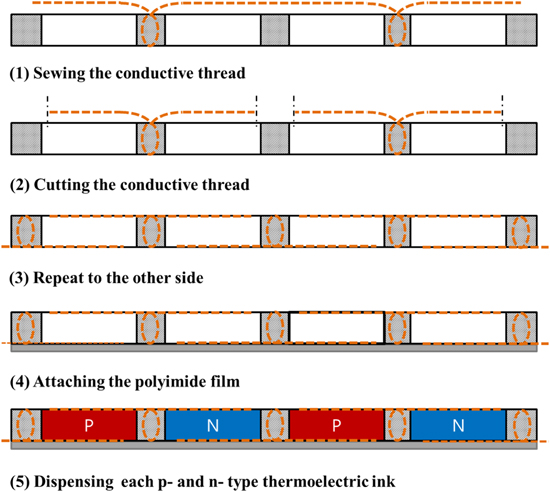
Figure 4. Process for sewing the conductive thread into the fabric.
Download figure:
Standard image High-resolution imageA top view (figure 5(a)) and a close-up view (figure 5(b)) of the fabricated device are shown. As shown in figure 5(c), the TEG is highly flexible and durable. After several bending tests, there was no further change to the electrical properties of the TEG. We confirmed that the TEG is strong enough for flexible applications. The total internal resistance of the 12 thermocouples is about 902 Ω.

Figure 5. (a) Image of the printed 12-couple TEG, (b) a close-up view of the dispenser-printed thermocouples and (c) a demonstration of bending the wearable TEG by hand.
Download figure:
Standard image High-resolution image4. Results
4.1. Thermoelectric generator characterization
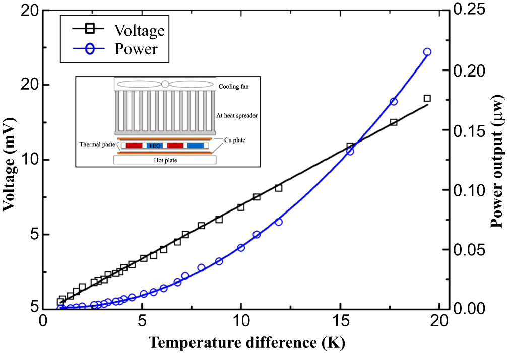
The wearable TEG was tested and characterized with the measurement setup. For this experiment, the setup consisted of a hot plate and an Al heat spreader (see the figure 7 inset). To reduce the thermal contact resistance, thermal paste was applied to the contact surface between the TEG and the copper plate.
Figure 6 shows the 12-couple TEG characteristic curves for the prototype at ΔT = 20 K. The power output was measured at various load resistances. The optimal output of the TEG occurred when the load resistance matched the internal resistance of about 900 Ω. At matched load resistance, the optimal power output is approximately 224 nW at 15.8 μA and 14.2 mV. Figure 7 shows the maximum voltage and power at matched load resistance that was measured with the variation of the temperature difference (ΔTTEG ). The temperature difference was considered as the measured data at the TEG surface of the top and bottom. The graph clearly shows the linearly increasing voltage with the increasing temperature difference. At the temperature difference of 19.2 K, the TEG generated a voltage of 14.1 mV and a power of 221 nW. A thermopower of 0.72 mV K−1 could be attained with a single device with only 12 thermocouples.
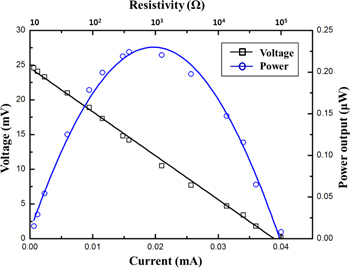
Figure 6. Characteristic curve for the 12-couple TEG at ΔT = 20 K.
Download figure:
Standard image High-resolution image
Figure 7. Voltage and power output for the 12-couple TEG at matched load resistance as a function of the temperature difference. The inset shows a schematic of the measurement setup.
Download figure:
Standard image High-resolution image4.2. Thermoelectric generator test on the human body
It was possible to integrate the TEG in the fabric of a shirt, as shown in figure 8. The fabricated device was worn on the wearer's chest; the chest is a large area and is the warmest part of the body. The measured skin temperature was about 32 °C, and the ambient temperatures for the cases of cold and hot environments were 5 °C and 25 °C, respectively. Table 2 shows the results of harvesting energy from the human body. All of the measurements have been carried out under outdoor conditions in a natural convection situation in which the wearer did not move. In the warm ambient air of 25 °C, the device generated less power (8.1 nW), but the output power of the TEG increased considerably, to as high as 146.8 nW, in the cold ambient air (5 °C).
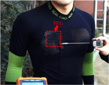
Figure 8. Photographs of the shirt with the TEG embedded for clothing applications.
Download figure:
Standard image High-resolution imageTable 2. The energy harvesting results for the wearable TEG being worn by a human subject.
| Body temperature (°C) | Ambient temperature (°C) | Output voltage (mV) | Output power (nW) |
|---|---|---|---|
| 32 | 25 | 2.7 | 8.1 |
| 32 | 5 | 11.5 | 146.9 |
When the wearer is walking, a significant amount of convection occurs, and the skin surface temperature is raised by the activity of movement. Thereby the amount of harvested power increased. We measured the output voltage as a function of time for two different states of motion (figure 9). The voltage change was observed for 1 min immediately after the subject began wearing the TEG. This figure shows that the voltage decreases as a function of time. The voltage reduction occurred due to the temperature equilibrium between the hot and cold junction. The first time the TEG came in contact with the skin, the temperature difference was the highest. But after the heat was transferred, the temperature difference decreased. After that, the voltage was maintained at a constant level by thermal equilibrium. A higher voltage was maintained while walking than in the stationary state. These results were maintained when running the experiment 10 times; averaging these experimental results yielded voltages of about 2.7 mV (stopped state) and 4.8 mV (walking state). The walking speed was approximately 1 m s−1, and the ambient temperature was measured to be 25 °C.

Figure 9. Voltage output on the human body when moving at an ambient temperature of 25 °C.
Download figure:
Standard image High-resolution image
5. Discussion
A typical adult produces approximately 2.4–4.8 W of power in the form of the body heat. Harvesting even 1-2% of that power can generate up to 96 mW [8]. The 12-couple prototype presented in this work generated 146.8 nW in cold ambient air (5 °C). The output power per cm2 can be calculated to be a power density of 292.4 nW cm−2. Given these results, the proposed wearable TEG could obtain 4.7 mW from about 1.6 m2 of total skin area of a typical adult. When compared to other similar studies, the performance is at a similar level with our results [14]. They printed thermoelectric materials to the fabric and coated the device with PDMS.
The prototype TEG had insufficient energy conversion efficiency to supply auxiliary power to portable electronics. The prototype has not been optimized to increase the areal power density. Many thermocouples must be integrated into the small area within the range of the TEG without compromising the flexibility of the device; and optimization of the fabrication and materials is also needed. The total device resistance can also be reduced through the sintering of the materials at higher temperatures [15]. Many researchers have investigated ways to improve thermoelectric materials. The nanowires technique significantly improved the performance of the conventional thermoelectric material, but it is still challenging to mass produce the naowires [16]. There are methods that utilize nanoparticles or nanostructured thermoelectric materials. These methods are considered to be suited for mass production in the future. Nano-SiC-dispersed Bi2Te3 was fabricated by mechanical alloying and SPS (spark plasma sintering) [17]. The thermoelectric properties were further improved through optimizing the SPS processing parameters and through the addition of nano-SiC. Nanostructured bulk alloys, as a way to improve performance, were made by hot pressing nanopowders from crystalline ingots under inert conditions [18]. Alternatively, it is possible to use a hybrid power harvesting scheme by employing other energy sources such as pyroelectric generators [19]. Pyroelectricity is the ability to generate voltage when changing the temperature. During the initial contact with the heat source, the harvester generates relatively high voltage. When applied in combination with thermoelectric generators, it is possible to obtain more energy. Furthermore, integration of a rechargeable thin film battery or a printable battery with presented thermoelectric & pyroelectric devices on clothing can provide a constant and more stable power source for electronics [20].
The dispenser printing method used in the prototype is simple but not suitable for mass production. The thermoelectric material processing methods in studies have many restrictions on mass production. Among them, a method of using a screen printing technique is thought to be suitable. The screen printing method suitable to mass production is similar to the dispenser printing method of using printable ink [21]. Thus, the screen printing method will be effective in large scale processes of the proposed device.
Body applications, as well as the proposed thermoelectric device, can be used in a variety of fields. Now, the trend is flexible and portable electronic devices. The flexible TEG assembled with these electronic devices will be able to increase the battery life time.
6. Conclusion
This paper describes a wearable TEG for human clothing applications. Thermoelectric materials Bi0.5Sb1.5Te3 (p-type) and Bi2Se0.3Te2.7 (n-type) were embedded into polymer fabric through the dispenser printing method. The fabricated prototype showed flexibility suitable for interacting with the human body, and we tested the thermoelectric performance of the prototype. The fabricated TEG, consisting of 12 thermocouples, had a thermopower output of about 0.72 mV K−1. The device produced 224 nW at 15.8 μA and 14.2 mV for a temperature difference of 15 K. When the device was worn, it was able to generate up to 146.8 nW in ambient temperatures of 5 °C.
The proposed TEG showed the feasibility of a wearable device in the form of clothing. This TEG can be applied to clothing for different parts of the body. By simply wearing such clothing to generate electrical energy, it is possible to generate enough energy to use low-power devices. However, the TEG device needs to be more efficient for human body applications. Our future work will focus on the development of a hybrid device, including optimization of the materials.
Acknowledgements
This research was supported by the Pioneer Research Center Program through the National Research Foundation of Korea, funded by the Ministry of Science; ICT & Future Planning (2011-0001672); and the Priority Research Centers Program through the Ministry of Education, Science and Technology (2009-0093823).