
Abstract
To provide tactile feedback on flexible touch screens, transparent relaxor ferroelectric polymer film vibrators were designed and fabricated in this study. The film vibrator can be integrated underneath a transparent cover film or glass, and can also produce acoustic waves that cause a tactile sensation on human fingertips. Poly(vinylidene fluoride-trifluoroethylene-chlorotrifluoroethylene) [P(VDF-TrFE-CTFE)] polymer was used as the relaxor ferroelectric polymer because it produces a large strain under applied electric fields, shows a fast response, and has excellent optical transparency. The natural frequency of this tactile-feedback touch screen was designed to be around 200–240 Hz, at which the haptic perception of human fingertips is the most sensitive; therefore, the resonance of the touch screen at its natural frequency provides maximum haptic sensation. A multilayered relaxor ferroelectric polymer film vibrator was also demonstrated to provide the same vibration power at reduced voltage. The flexible P(VDF-TrFE-CTFE) film vibrators developed in this study are expected to provide tactile sensation not only in large-area flat panel displays, but also in flexible displays and touch screens.
Export citation and abstract BibTeX RIS
1. Introduction
Recently, tactile-feedback technology that provides touch sensation in mobile electronic devices has received a great deal of attention since touch sensation, along with visual and auditory recognition, greatly contributes to more realistic user experiences [1–15]. When operating a touch screen, a user naturally senses tactile feedback since he or she operates the touch screen with a finger. There have been ongoing efforts to use additional actuators to provide tactile feedback related to the object displayed on the screen [16]. When considering stimulation recognition in humans, the provision of feedback to the user, in combination with two or more modalities such as visual, auditory and tactile, has resulted in more natural interaction with electronic devices. The haptic actuators most widely used in smart phones and tablets today are inertia-type actuators, such as linear resonant actuators or eccentric rotating motors. Inertia-type actuators, operated by a mass vibrating between two magnets, are small in size and require relatively little power consumption. Meanwhile, piezoelectric actuators that produce vibration under an applied electric field are also being used. These actuators have a relatively high response speed of less than 5 ms, and various touch sensations can be implemented by widely varying the operating frequency. However, in providing touch sensations of sufficient strength, their relatively high power consumption is a distinct disadvantage. On the other hand, Artificial Muscle Inc. (Sunnyvale, CA, USA) developed a haptic-feedback device operated by dielectric elastomer actuators, in which an alternating electric field is applied to various single-layer and multilayered dielectric elastomer structures [10].
Haptic sensation is caused by physical contact between human skin and an object. In particular, the surface characteristics of the object perceived by the user through the skin, including surface roughness, fine pattern, sense of heat, and friction, are called 'tactile sensation.' For the touch screen to provide realistic user experiences as if the user were directly touching and interacting with the multimedia objects displayed on the screen, numerous studies on various actuators that provide tactile feedback have recently been pursued [11–16]. In particular, tactile-feedback devices using electrostatic force [11–13] are considered to be a promising technology for large-area touch screens, since they are transparent and can express various textures, including smoothness, roughness, softness, and vibration, by varying the vibration strength and frequency. There are two main methods for utilizing electrostatic force: using a change in the electrostatic force between fingertip and transparent electrodes [12, 13], or charging two electrode layers separated by a dielectric material [11]. Research on tactile interfaces is not limited to physical aspects, but also includes emotional aspects, such as the changes in sensations or emotions that a user experiences from vibrations felt through the fingertip [17, 18]. Strength and frequency of vibration are regarded as especially important external design parameters which may control the sensitivity of vibration stimulation. It has also been reported that vibration at the low frequency range of 20–80 Hz is weakly felt by the finger, while vibration in the 150–250 Hz frequency range is most effective for information delivery through haptic feedback [16].
Flexible displays, such as organic light-emitting diode displays, are able to bend and roll without damage [19–23]. Interestingly, it is worth noting that for now, flexible touch displays are used in curved and hard surfaces in which conventional tactile-feedback devices may be still useful. However, future flexible displays, which are bendable and deformable, are expected to be equipped with other types of flexible user interfaces. Lahey et al [23] investigated the effectiveness of various bend gestures with a prototype of flexible smartphones with bend sensors. Even though the need for tactile feedback on flexible touch screens is not yet demonstrated, it is conceivable that tactile feedback on flexible touch screens will provide better user experiences. Most existing haptic devices used in handheld electronics are opaque and provide only gross vibration, which is not suitable for flexible displays. Except for haptic devices that use electrostatic force [11–13], little research on tactile feedback has been completed that is applicable to flexible touch screens. Therefore, a flexible and transparent film-type actuator must be developed to produce tactile feedback in flexible displays.
Poly(vinylidene fluoride) (PVDF)-based ferroelectric polymers are one of the most promising field-activated electroactive polymers due to their relatively easy process, large and fast electromechanical response, high mechanical and chemical stability, lightness, and low mechanical and acoustic impedance [24–28]. Among various PVDF-based ferroelectric polymers, poly(vinylidene fluoride-trifluoroethylene) [P(VDF-TrFE)], which is composed of the two monomers vinylidene fluoride (VDF) and trifluoroethylene (TrFE), is the most widely used due to its high crystallinity and correspondingly high piezoelectric property. In order to induce piezoelectric characteristics in P(VDF-TrFE), poling treatment with a high electric field must be conducted to align the electrical dipoles within the material. Meanwhile, P(VDF-TrFE)-based terpolymers such as poly(vinylidene fluoride-trifluoroethylene 1, 1-chlorofluoroethylene) [P(VDF-TrFE-CFE)] and poly(vinylidene fluoride-trifluoroethylene-chlorotrifluoroethylene) [P(VDF-TrFE-CTFE)] show relaxor ferroelectric characteristics, in which the third monomer CFE or CTFE introduces defects in the ferroelectric P(VDF-TrFE) copolymers, and thus breaks the coherent polarization domain into nanopolar regions [24, 25]. These nanopolar regions enable a transverse strain of more than 5% under an electric field of 150 V μm−1 without poling treatment. However, this level of electric field requires high driving voltages—for example, about 500 V in a 10 μm-thick P(VDF-TrFE-CFE) film to generate an electric field of 50 V μm−1. These high driving voltages restrict wide application of these polymers to circumstances where high voltages are not available (e.g., handheld electronic devices). Recently, to reduce the driving voltage of relaxor ferroelectric polymer actuators, Choi et al [29] used an adhesion-mediated film transfer technique to fabricate multilayered relaxor ferroelectric P(VDF-TrFE-CTFE) actuators. However, the multilayered P(VDF-TrFE-CTFE) actuators were not transparent, since aluminum electrodes were used. If the aluminum electrodes are replaced with transparent electrodes, transparent multilayered P(VDF-TrFE-CTFE) actuators can be created, since PVDF-based ferroelectric polymers have an especially high light transmittance of 93% in a one-mm-thick film.
Transparent electrodes, which are widely used in displays, touch screens, solar cells, and optoelectronic devices, have light transmittance greater than 80% in the visible light spectrum (380 nm–780 nm) and sheet resistance below 500 Ω sqm−1. Currently, the most widely used transparent electrode is indium tin oxide (ITO) [21]. This material has both excellent transmittance characteristics in the visible light spectrum and relatively low electric resistance. However, ITO is not well-suited for flexible display applications because of its brittleness, which causes it to fracture easily with bending deformation. Moreover, the fabrication cost of ITO is relatively high due to its vacuum deposition process. On the other hand, transparent electrodes using graphene, carbon nanotubes, and organic materials are actively being developed [30, 31]. Representative conductive polymers include poly(3,4-ethylenedioxythiophene) (PEDOT) and its derivatives; among these derivatives, poly(3,4-ethylenedioxythiophene):poly (styrenesulfonate) (PEDOT:PSS) is the most widely used organic electrode. Since PEDOT:PSS has excellent transparency, conductivity, thermal resistance, and stability, it has already been commercialized. Additionally, since PEDOT:PSS films like other organic films are flexible and bendable, they may be widely used in flexible electronic devices in the near future.
This study aims to develop a flexible transparent film vibrator using relaxor ferroelectric P(VDF-TrFE-CTFE) polymers to provide tactile sensations not only in large-area flat panel displays, but also in flexible displays. The film vibrator can be attached in the form of a sheet underneath either the transparent cover film or the glass of a flexible display. The film vibrator can produce acoustic vibrations that cause a tactile sensation perceivable by human fingertips. Section 2 explains the operational principle and structural design of the film vibrator. The electrical and vibrational design of the film vibrator combined with a flexible touch screen is also described in section 2. Section 3 illustrates the fabrication processes of the film vibrator. The fabrication results and performance results are discussed in section 4. A transparent, multilayered film vibrator that provides the same power of vibrations at a reduced voltage is also demonstrated in section 4. Finally, section 5 concludes this study.
2. Design and analysis
2.1. Design of a flexible, tactile-feedback film vibrator
In this section, we propose a film vibrator to provide haptic sensation to a flexible, tactile-feedback touch screen, whose schematic illustration and cross-sectional design are shown in figures 1(a) and (b), respectively. Capacitive touch sensors are located underneath the cover protection layer. Therefore, when a user's fingertips come into direct contact with the cover layer, the touch sensors detect the contact of the user's fingertips. A film vibrator can be placed underneath the touch sensors as shown in figure 1(b); such a film vibrator is composed of an upper transparent electrode, ferroelectric polymer film, and a lower transparent electrode. Therefore, the cover layer, touch sensors, upper electrode, ferroelectric polymer film, and lower electrode form a multilayered structure. Since all of the components of the multilayered structure are transparent and do not hinder light transmittance, the flexible display panel can be placed under the multilayered structure. When an alternating electric field is applied to the ferroelectric polymer film through the upper and lower electrodes, the ferroelectric polymer film produces repeated contraction and expansion, which are converted to a bending vibration of the multilayered structure; in turn, human fingertips can sense the bending vibration. Therefore, the touch sensors and the film vibrator may incorporate the content displayed in the flexible display panel to provide a realistic user experience.
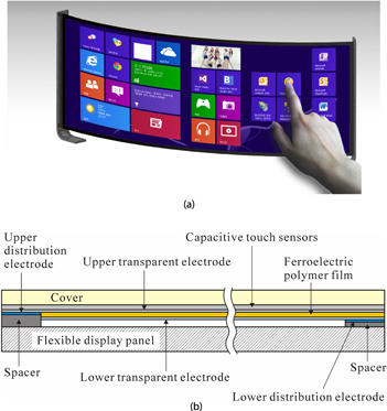
Figure 1. (a) Schematic illustration of a flexible, tactile-feedback touch screen; and (b) cross-sectional design of a flexible, tactile-feedback touch screen operated with a gross-mode film vibrator.
Download figure:
Standard image High-resolution imageIt is worth noting that transparent electrodes have higher electrical resistance than metal electrodes, so when the size of the transparent electrodes increases, the voltage drop within transparent electrodes becomes significant. To reduce the resistance of the transparent electrodes, the thickness of the transparent electrodes must increase. However, such an increase would cause a decrease in the transparency and performance of the film vibrator. In addition, when voltage is applied to the transparent upper and lower electrodes, a minute amount of current leaks through the ferroelectric polymer film. This results in the ferroelectric polymer film having both capacitance and resistance, like a dielectric material. Therefore, in order to apply a uniform electric field to the ferroelectric polymer film, high-electric-conductivity metal electrodes must be placed as distribution electrodes at the edges of the display area, as shown in figure 1(b). Upper and lower metal electrodes, as the distribution electrodes, are located on opposite sides of the display device, and thus the sum of the distances from any point on the actuator to the upper and lower metal electrodes are equal. Therefore, the voltage drop produced at the transparent electrodes is the same everywhere, making the magnitude of the electric field on the ferroelectric polymer film equal everywhere, and making the actuation performance consistent.
2.2. Composite beam analysis of the film vibrator
In this section, the principle behind the deformation of the transparent ferroelectric polymer film vibrator shown in figure 1(b) is examined and its deflection size is estimated. When voltage is applied to the upper and lower transparent electrodes, the relaxor ferroelectric polymer contracts in the thickness direction and expands in the length direction. Here, a longitudinal strain,  , in the relaxor ferroelectric polymer layer sandwiched between two electrodes is a monotonically increasing function of the applied electric field,
  . This longitudinal strain can be converted into bending deformation by using bimorph structures composed of an active layer and an inactive layer. The upper part of the flexible, tactile-feedback touch screen in figure 1(b) consists of a cover, capacitive touch sensors, upper transparent electrode, ferroelectric polymer film, and lower transparent electrode; it is considered to be a bimorph structure with an active layer (ferroelectric polymer film and electrodes) and an inactive layer (cover and capacitive touch sensors). Therefore, a composite beam analysis of the flexible, tactile-feedback touch screen shown in figure 2 is conducted here, in which multilayered, ferroelectric polymer actuators are considered to be the film vibrator. If there are N ferroelectric polymer layers for actuation, the multilayered film vibrator is composed of (2N + 3) layers, as shown in figure 2. To estimate the bending deformation caused by the longitudinal strain,
  , we used the so-called 'cut and paste' technique, which is a well-known procedure for calculating the bending deformation of composite beams due to eigenstrains, e.g., thermal strain, as illustrated in Ref. [32]. The
  ferroelectric polymer layer would undergo the longitudinal strain,
  , under the electric field
  , if the
  ferroelectric layer were free of any constraint. In order to recover the original length of the
  ferroelectric layer, the fictitious stress
  needs to be applied at both ends of the
  ferroelectric layer. The fictitious bending moment,
  , with respect to the neutral axis of the composite beam, can also be calculated with these fictitious stresses. Therefore, the bending moment,
  , per unit length caused by the longitudinal strain of ferroelectric polymer layers under the applied electric field, is given as [33]

where  is Young's modulus of ferroelectric polymer layers,
  is the thickness of the
  layer, and
  represents the voltage difference between the
  and
and  electrodes. The strain response of the relaxor ferroelectric polymers, such as P(VDF-TrFE-CFE) and P(VDF-TrFE-CTFE), was measured as a function of the electric field by Zhang et al [26]. As a rough approximation, the longitudinal strain,
  , can be assumed to be linearly proportional to the applied electric field,
  —that is,
  , where
  [26]. If needed, the experimental results can be curve-fitted. In our study, the longitudinal strain is assumed to be a special function of the electric field in section 4.1, in order to take the nonlinear strain response into account in the range of low electric field. The positions of the neutral axis of the
  layer and the composite beam measured along the y axis, as shown in figure 2, are respectively given as


where  is Young's modulus of the
  layer. Then, a composite beam subject to the moment given in equation (1) may be in a state of pure bending deformation, for which the maximum deflection,
  , can be expressed as [33]

Here,  is the effective flexural modulus per unit length of the film vibrator, expressed as


Figure 2. Schematic view of a cross section of a multilayered film vibrator for composite beam analysis.
Download figure:
Standard image High-resolution imageAlso,  is the effective length of the composite beam, which varies according to the boundary conditions and the resonance mode. Equation (4) can be used to calculate the maximum deflection of the film vibrator using static composite beam analysis. To simplify the calculation, it is assumed that the thicknesses of all the ferroelectric polymer layers are equal, i.e.
  , and the applied voltage differences are the same, i.e.
  . Then, the following equation can be obtained by substituting equation (1) into equation (4):
Equation (6) predicts the deflection magnitude generated by the film vibrator and can be used in the design of the film vibrator, since the effects of various design parameters on the deflection can be identified from equation (6).
2.3. Modal analysis of film vibrator for haptic sensation
In order to provide excellent haptic sensation to the user by means of the vibration generated by the transparent ferroelectric polymer film vibrator designed in previous sections, this section discusses the vibration design of flexible, tactile-feedback touch screens. When periodic voltage is applied to a ferroelectric polymer film, periodic lateral vibration is generated by the film vibrator, which can provide tactile sensation. Resonance design is applied to maximize the lateral vibration of the film vibrator. In other words, the upper part of the flexible, tactile-feedback touch screen is designed to have its resonant frequency equal to the frequency at which human fingertips most effectively sense vibrations (150–250 Hz). When a driving voltage is applied at the resonant frequency, the vibration amplitude dramatically increases due to the resonance of the upper part of the flexible, tactile-feedback touch screen. This dramatic increase in the vibration amplitude provides excellent haptic sensation. The natural frequency of the composite beam,  , can be calculated by the following formula [34]:

Here, the effective mass per unit area of the composite beam,  , can be expressed as

where  is the density of the
  layer. Also,
  of equation (7) is the eigenvalue of the
  vibration mode determined by the boundary condition. Therefore, the natural frequency calculated from equation (7) depends on the boundary condition, such as whether the film vibrator is simply supported or fixed on the edge of the flexible display panel. Thus, equation (7) and equation (6) predict the magnitude of the vibration generated by the film vibrator and determine the effects of various design parameters, which makes the equations valuable in the vibration design of the film vibrator. For example, the effective flexural modulus
  of the film vibrator, including the cover, has to be designed to be greater than the specific value for the reliability of the device. However, as seen in equation (6), if
  becomes too large, the deflection value, which is inversely proportional to
  , decreases, resulting in the reduction of the haptic-feedback effect. Moreover, since the natural frequency is proportional to the square root of
  , as seen in equation (7), it can be used when designing the resonant frequency to match the frequency range at which human fingertips most effectively sense vibrations (150–250 Hz). The application of the modal analysis presented in this section is explained in more detail in section 4.
3. Fabrication
3.1. Fabrication of relaxor ferroelectric polymer films
Relaxor ferroelectric polymer P(VDF-TrFE-CTFE), in which mole fractions of VDF, TrFE, and CTFE monomers are 62.7, 29.6, and 7.7 percent, respectively, was synthesized at Piezotech S.A. in France [35]. Ten grams of P(VDF-TrFE-CTFE) polymer were dissolved in 90 g of methylisobutylketone and the solution was filtered with a polytetrafluoroethylene filter with 1.0 μm-sized pores. The filtered solution was kept at room temperature for 24 h to remove trapped microbubbles. To fabricate and handle P(VDF-TrFE-CTFE) films, the adhesion-mediated film-transfer technique developed by Choi et al [29] was used. To conduct this detailed procedure, the P(VDF-TrFE-CTFE) polymer solution is dispensed and applied onto a glass plate with a film applicator. The film applicator has a fixed gap thickness, so the solution is spread uniformly onto the glass plate. The solvent is evaporated from the solution, and a dry P(VDF-TrFE-CTFE) film is formed on the glass plate. A silicone elastomer film, acting as a support film, is laminated at room temperature on top of the dry P(VDF-TrFE-CTFE) film on the glass plate. To weaken the interfacial adhesion between the P(VDF-TrFE-CTFE) film and the glass plate by diffusion of water molecules along the interface, the P(VDF-TrFE-CTFE) film sandwiched between the support film and the glass plate is immersed in deionized water for two hours. The P(VDF-TrFE-CTFE) film and the support film are debonded from the glass plate in deionized water. The P(VDF-TrFE-CTFE) film on the support film is annealed at 115 °C for two hours to remove any remaining solvent and to increase crystallinity.
3.2. Patterning of organic electrodes on a P(VDF-TrFE-CTFE) film
This section describes a method for patterning organic electrodes on a P(VDF-TrFE-CTFE) film. PEDOT:PSS (ORGACON IJ-1005, Agfa-Gevaert Group) was used as the conducting polymer. Since the P(VDF-TrFE-CTFE) film fabricated by the adhesion-mediated film-transfer technique is placed on a support film, PEDOT:PSS can be deposited onto the P(VDF-TrFE-CTFE) film. Dark-blue-colored PEDOT:PSS needs to be applied with minimum thickness in order to obtain high transparency. In this research, a digital ultrasonic generator (Sonaer Inc.) was used to excite a wide-spray atomizer nozzle (WS130K50S, Sonaer Inc.) at a frequency of 130 kHz, and PEDOT:PSS solution was sprayed as droplets with an average diameter of 11.8 μm (see figure 3(a)). Before the spray coating, the surface of the P(VDF-TrFE-CTFE) film was treated with O2 plasma at 50 W for five minutes in order to enhance the adhesion of the PEDOT:PSS to the P(VDF-TrFE-CTFE) film. Also, to pattern the PEDOT:PSS electrode, a shadow mask, as shown in figure 3(b), was fabricated and placed on the P(VDF-TrFE-CTFE) film. When the PEDOT:PSS solution was sprayed with the ultrasonic atomizer on the P(VDF-TrFE-CTFE) film covered with the shadow mask, a PEDOT:PSS electrode pattern was formed, as shown in figure 3(c).
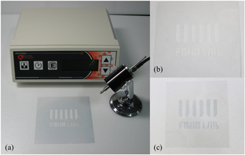
Figure 3. (a) A digital ultrasonic generator (Sonaer Inc.) with a wide-spray atomizer nozzle (WS130K50S, Sonaer Inc.); (b) a shadow mask fabricated with a PET film; and (c) PEDOT:PSS electrode patterned with the shadow mask. (Contrasts of (b) and (c) were adjusted to make the patterns be seen clearly.).
Download figure:
Standard image High-resolution image3.3. Assembly
In this section, we explore how the flexible, tactile-feedback touch screen shown in figure 1(b) was integrated with the parts prepared in previous sections. A 188 μm-thick polyethylene terephthalate (PET) film covered with a thin ITO electrode was used as the cover film. Although figure 1(b) shows the capacitive touch sensors placed underneath the cover, capacitive touch sensors were not considered in this study since this research focused on the fabrication of the flexible, tactile-feedback film vibrator. The P(VDF-TrFE-CTFE) film atop a support film was first laminated at 110 °C onto the PET film cover with the ITO electrode; then, the support film was removed. Since the P(VDF-TrFE-CTFE) film undergoes partial melting depending on the micro-phases at about 110 °C (which is just below the melting temperature of P(VDF-TrFE-CTFE) film), the P(VDF-TrFE-CTFE) film and ITO coating adhere with appropriate adhesion strength. The organic electrode, PEDOT:PSS, was deposited onto the P(VDF-TrFE-CTFE) film/ITO/PET structure according to the procedure described in section 3.2. Here, the PEDOT:PSS electrode and ITO electrode were arranged so that their edges do not overlap, as shown in figure 1(b). Conducting tape was attached on exposed ITO and PEDOT:PSS surfaces to act as the upper and lower distribution electrodes, respectively. Finally, another PET film and color-printed paper were placed as a mock-up of the flexible display panel, as shown in figure 1(b). Figure 4 shows the flexible, tactile-feedback touch screen developed in this study.
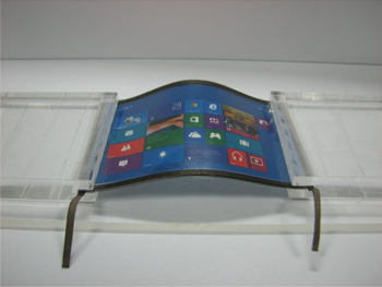
Figure 4. Flexible, tactile-feedback touch screen fabricated with a P(VDF-TrFE-CTFE) film vibrator.
Download figure:
Standard image High-resolution image4. Results and discussion
4.1. Estimation of vibration amplitude from composite beam analysis
To investigate the vibration characteristics of the fabricated, flexible, tactile-feedback touch screen, the composite beam analysis explained in section 2.3 was performed. Figure 1(b) shows the schematic view of the cross section of the flexible, haptic-feedback touch screen. Here, the cover layer was a 188 μm-thick PET film; the capacitive touch sensor was not integrated, for manufacturing convenience. Also, the upper and lower electrodes used were ITO and PEDOT:PSS, respectively, and P(VDF-TrFE-CTFE) film was used as the ferroelectric polymer. The total dimensions were 85 mm × 60 mm and the dimensions of the actuation region were 65 mm × 40 mm. Table 1 shows the Young's modulus, density, and thickness of each material used in the fabrication of the flexible, haptic-feedback touch screen. Although vibration analysis may be necessary to optimize the flexible, haptic-feedback touch screen and to estimate its maximum deflection, the design parameters of the film vibrator can be qualitatively determined by the static deflection given in equation (6). First, the longitudinal strain,  , induced in the P(VDF-TrFE-CTFE) film under an applied electric field,
  , is assumed to have the following mathematical form:

It should be noted from equation (9) that  and
and  , and the strain monotonically increases as the electric field increases. The longitudinal strain given in equation (9) can be considered an approximation of the measured strain response [26]; the unit of electric field is MV m−1. It is worth noting that the second term of equation (9) was introduced to account for the reduction of the longitudinal strain response in the range of electric field, 0 ∼ 10 MV m−1. Figure 5 shows the normalized deflection of the film vibrator as a function of the thickness of the P(VDF-TrFE-CTFE) film for the various applied voltages and number of P(VDF-TrFE-CTFE) films. It should be noted that as the thickness of the P(VDF-TrFE-CTFE) film,
  , decreases for a given voltage, the electric field applied to the P(VDF-TrFE-CTFE) film increases, but the force generated by the P(VDF-TrFE-CTFE) film decreases. As can be seen in figure 5, the compromise between the electric field and the force results in an optimal thickness of the P(VDF-TrFE-CTFE) film around
  = 5 μm, for which the film vibrator produces maximum deflection. This trend can be changed if the longitudinal strain,
  , has a function form different from equation (9). Unfortunately, the experimentally measured longitudinal strain,
  , especially in the low electric field region of less than 10 V μm−1, is not sufficient to determine a precise function form. However, it is certain from figure 5 that the optimal thickness of the P(VDF-TrFE-CTFE) film, which gives the maximum deflection, is between five and 15 micrometers.
Table 1. Young's moduli, densities and thicknesses of the layers used in the flexible, tactile-feedback touch screen.
| Layer | Material | Young's modulus (GPa) | Density (kg m−3) | Thickness (μm) |
|---|---|---|---|---|
| Cover | PET | 2.5 | 1380 | 188 |
| Ferroelectric polymer | P(VDF-TrFE-CTFE) | 0.4 [13] | 1780 | 0.1–30 |
| Upper transparent electrode | Indium tin oxide | 114 | 7140 | 0.1 |
| Lower transparent electrode | PEDOT:PSS | 1.0 | 1011 | 0.2 |
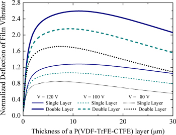
Figure 5. Normalized vibration amplitudes of the flexible, tactile-feedback film vibrator as a function of the thickness of P(VDF-TrFE-CTFE) layers.
Download figure:
Standard image High-resolution imageMeanwhile, the tactile-feedback touch screen developed in this study is transparent and flexible, making it suitable for application in future flexible-display devices, but one disadvantage may be that it requires a high driving voltage. It can be seen in figure 5 that the normalized deflection is almost linearly proportional to the applied voltage. When the driving voltage increases, the displacement and the vibration strength increase, but the high driving voltage may not be available in mobile electronic devices. To decrease the driving voltage, the thickness of the P(VDF-TrFE-CTFE) film must be decreased, but doing so makes it difficult to obtain the desired level of power. To overcome this obstacle, P(VDF-TrFE-CTFE) films need to be stacked to form multilayered film vibrators. Figure 5 also shows that when double layers of P(VDF-TrFE-CTFE) film are used as the film vibrator, the normalized deflection becomes almost double with the same voltage. Of course, it can be inferred that stacking more layers will proportionally increase the generated amplitude at the same voltage. Therefore, a multilayered structure is advantageous for producing vibrations of great amplitude at a low voltage.
4.2. Vibration characteristics of the film vibrator
The flexible, tactile-feedback film vibrator developed in this study was attached to a fixture, as shown in figure 6, and operated to measure its dynamic performance. A sinusoidal-waveform voltage was generated by an arbitrary waveform generator (Agilent, Model: 33210A). Then, the sinusoidal-waveform voltage was amplified by a high-voltage amplifier (Trek, Model: 623B). The vibration amplitude produced by the film vibrator was measured using a laser Doppler velocimetry, as shown in figure 6. Figure 7 shows the measured maximum vibration amplitude of the film vibrator as a function of frequency. Here, it was found that the resonance occurs at about 220 Hz, where the vibration amplitude dramatically increases. Calculating the resonant frequency using equation (7) gives  = 177 Hz when the boundary condition is simply supported, and
  = 401 Hz when the boundary condition is fixed. This result shows that the boundary condition of the film vibrator supported by a fixture, as shown in figure 6, is close to the simply supported boundary condition. The resonance of the film vibrator at 220 Hz, as shown in figure 7, greatly enhances the user's haptic sensation, since human fingertips are most sensitive to vibration at frequencies between 150–250 Hz. Approximately 50 people tested the flexible, tactile-feedback touch screen and stated that the vibration it generated was strong enough for haptic sensation.
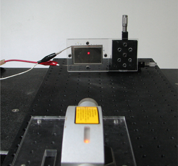
Figure 6. Experimental setup with laser Doppler velocimetry to measure the vibration amplitude of the fabricated film vibrator.
Download figure:
Standard image High-resolution image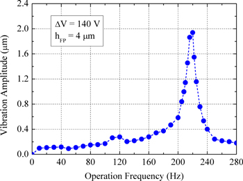
Figure 7. Maximum vibration amplitude of a film vibrator fabricated with a 4 μm-thick P(VDF-TrFE-CTFE) film as a function of the operation frequency.
Download figure:
Standard image High-resolution imageIn order to reduce the driving voltage of the flexible, tactile-feedback touch screen, a double-layered P(VDF-TrFE-CTFE) film vibrator was also fabricated. Figure 8 shows the measured maximum vibration amplitudes of the film vibrators fabricated with single P(VDF-TrFE-CTFE) films four μm and eight μm thick, and with double P(VDF-TrFE-CTFE) films four μm thick. The frequency of the applied voltage was 220 Hz for resonance, and the amplitudes were measured at the center of the film vibrator. First, the vibration amplitude of the film vibrator fabricated with the single, eight-μm-thick P(VDF-TrFE-CTFE) film was greater than that of film vibrator fabricated with the single, four-μm-thick P(VDF-TrFE-CTFE) film. This result agrees with the prediction from figure 5, in which an increase in the P(VDF-TrFE-CTFE) film's thickness leads to an increase in the deflection by a small margin, when the P(VDF-TrFE-CTFE) film's thickness is less than about 10 μm. More importantly, the vibration amplitude of the film vibrator fabricated with double P(VDF-TrFE-CTFE) films that are four μm thick is significantly greater than the vibration amplitudes in the other two cases. In other words, the single-layer film vibrator exhibited approximately 0.6 μm ( = 4 μm) and 1.3 μm (
 = 8 μm) vibration amplitudes for 100 V, while the double-layered film vibrator showed a vibration amplitude of approximately 3.3 μm for 100 V. Therefore, stacking thin relaxor ferroelectric polymer films to construct a film vibrator provides an excellent solution for generating large vibration amplitude with reduced driving voltage.

Figure 8. Maximum vibration amplitudes of film vibrators fabricated with 4 μm-thick and 8 μm-thick P(VDF-TrFE-CTFE) films as a function of applied voltage.
Download figure:
Standard image High-resolution image4.3. Tactile sensation by the film vibrator
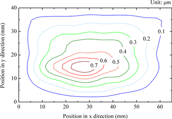
The flexible, tactile-feedback film vibrator fabricated in this study was shown to provide sufficient haptic sensation when the user's fingertips make physical contact with the device. Moreover, we discuss a method that makes full use of the developed film vibrator to provide various types of tactile feedback regarding the surface characteristics of objects, such as surface roughness, minute patterns, sense of heat, and friction. Tactile sensation may be realized by varying the vibration amplitude, waveform, and frequency of the tactile-feedback device [13]. The vibration amplitude and waveform of the film vibrator proposed in this study can be easily changed by controlling the applied driving voltage and waveform, respectively. However, the operation frequency cannot be arbitrarily changed, since it is restricted by the natural frequency of the film vibrator, which magnifies the vibration amplitude by resonance. To operate a flexible, tactile-feedback film vibrator in various frequency values, it is useful to design the film vibrator to have various natural frequencies, at which various tactile sensations can be realized. In other words, most touch panels have different length and width dimensions, so the natural frequencies in the length and width directions can be designed to be different, allowing two resonant frequencies. Also, when touch panels are sufficiently large in size, higher-order natural frequencies will fall into the frequency range (150–250 Hz) in which human fingertips are most sensitive, and thus, higher-order natural frequencies can be used as the operation frequencies for resonance. In particular, if the fundamental natural frequencies are only used as the resonant frequencies, the corresponding deformation shape of the film vibrator will result in reduced amplitude near the edge of the touch screen;thus, tactile sensation near the edge would be diminished. Figure 9 shows the contour plot of the measured vibration amplitude of the film vibrator fabricated with a single eight-μm-thick P(VDF-TrFE-CTFE) film. It should be noted that the largest vibration amplitude is located near the center of the film vibrator and the vibration amplitude decreases close to the edge. This implies that the edge of the tactile-feedback touch screen provides a weaker tactile sensation in comparison to the center. Even though the vibration amplitude near the edge is very weak, the vibration amplitude on almost all of the flexible screen is larger than the detection threshold of human sensitivity [16]. Furthermore, the tactile sensation near the edge can be enhanced if both the fundamental natural frequencies and the higher-order natural frequencies are used as operation frequencies to generate multiple deformation shapes, which have a considerable amount of vibration amplitude near the edge area. At the same time, the operation of the film vibrator at various higher-order resonance frequencies can be used to provide various tactile sensations to human fingertips in both the center area and the edge area.
Figure 9. Contour plot of the measured vibration amplitude of a film vibrator fabricated with a single 8 μm-thick P(VDF-TrFE-CTFE) film. The applied voltage and operation frequency were 100 V and 220 Hz, respectively.
Download figure:
Standard image High-resolution image
5. Conclusions
In order to provide tactile feedback not only on large-area flat panel displays but also on flexible displays and touch screens, flexible and transparent P(VDF-TrFE-CTFE) polymer film vibrators were designed and fabricated in this study. The natural frequency of the flexible, tactile-feedback touch screen was designed to be around 200–240 Hz, at which the haptic perception of human fingertips is the most sensitive. The film vibrator was integrated underneath a transparent cover film, which can be placed on top of a flexible display panel. When the film vibrator was operated at its resonance frequency (220 Hz) and applied voltage (100 V) the touch screen produced more than one μm of vibration amplitude, which was proven to be large enough for haptic sensation. Composite beam analysis was performed to estimate the deflection of the film vibrator as a function of the thickness of the P(VDF-TrFE-CTFE) film, which provides an optimal thickness of about 5 μm for the P(VDF-TrFE-CTFE) film. To reduce the driving voltage of the flexible, tactile-feedback touch screen, multilayered P(VDF-TrFE-CTFE) film vibrators were proposed, and double-layered P(VDF-TrFE-CTFE) film vibrators were fabricated which generated vibration amplitudes greater than twice that of the single-layer P(VDF-TrFE-CTFE) film vibrator of the same thickness. A method to provide various tactile sensations with the film vibrator was proposed, in which the vibration amplitude, waveform, and frequency can be controlled. The flexible, tactile-feedback film vibrator developed in this study is considered to be a promising technology for providing tactile sensations in flexible displays and touch screens.
Acknowledgements
This research was supported by the Basic Science Research Program through the National Research Foundation of Korea (NRF), funded by the Ministry of Science, ICT and Future Planning (Grant No. NRF-2011-0014226), Republic of South Korea.