

Abstract
This study presents a triple hybrid energy harvesting system that combines harvested power from thermoelectric (TE), vibration-based electromagnetic (EM) and piezoelectric (PZT) harvesters into a single DC supply. A power management circuit is designed and implemented in 180 nm standard CMOS technology based on the distinct requirements of each harvester, and is terminated with a Schottky diode to avoid reverse current flow. The system topology hence supports simultaneous power generation and delivery from low and high frequency vibrations as well as temperature differences in the environment. The ultra-low DC voltage harvested from TE generator is boosted with a cross-coupled charge-pump driven by an LC oscillator with fully-integrated center-tapped differential inductors. The EM harvester output was rectified with a self-powered and low drop-out AC/DC doubler circuit. The PZT interface electronics benefits from peak-to-peak cycle of the harvested voltage through a negative voltage converter followed by synchronous power extraction and DC-to-DC conversion through internal switches, and an external inductor. The hybrid system was tested with a wearable in-house EM energy harvester placed wrist of a jogger, a commercial low volume PZT harvester, and DC supply as the TE generator output. The system generates more than 1.2 V output for load resistances higher than 50 kΩ, which corresponds to 24 μW to power wearable sensors. Simultaneous multi-mode operation achieves higher voltage and power compared to stand-alone harvesting circuits, and generates up to 110 μW of output power. This is the first hybrid harvester circuit that simultaneously extracts energy from three independent sources, and delivers a single DC output.
Export citation and abstract BibTeX RIS
1. Introduction
Utilizing scavenged energy from environment becomes viable with the decreasing power demand of the new generation integrated circuits. Moreover, maintenance and replacement cost of electrochemical energy sources like batteries can be reduced by replacing these sources with energy harvesting structures [1, 2]. Most common ambient sources for mobile systems are solar, thermal, vibration and radio-frequency (RF) energy [3–7]. However, these ambient sources are not available all the time and each micro-harvester by itself is typically limited in power generation capacity, and output voltage level. Therefore, hybrid systems that effectively harvest multiple sources have become attractive [8–10].
Several attempts have been reported in literature to build hybrid energy harvesters. Hybrid system presented in [11] combines vibration based piezoelectric (PZT) and electromagnetic (EM) harvesters to drive the load with a full-wave rectifier circuit, which limits power output. In [12] a hybrid PZT and electrostatic harvester system is implemented on a flexible substrate to generate power from vibration; however electrostatic harvester requires 8 V DC offset voltage for operation that prevents portability of the system. Both [11, 12] utilize vibration as the sole environmental source for scavenging, but combining different ambient sources offers more viability to the system. The hybrid system depicted in [13] combines RF and vibration based PZT harvester structures to power a wireless sensor by switching between the two harvester outputs. Another hybrid structure, which utilizes thermoelectric (TE) and photovoltaic harvesters in order to generate individual power sources for multi-sensor wireless microsystem is described in [14]. The implemented system uses a microcontroller to coordinate the power source to supply different sensors at the microsystem. The proposed structures in [13, 14] are useful when scavenged power from either harvester is sufficient to maintain the load, but do not effectively couple multiple harvesters to increase total power capacity.
In this paper, a triple hybrid structure is presented, which simultaneously combines scavenged power from TE, vibration based EM, and PZT harvesters to support higher loads at the output. The hybrid system combines all three harvester outputs with a power management circuit, and provides a single DC supply. The AC power generated by EM and PZT harvesters is converted into ∼1 V DC, as the low-voltage output of the wearable TE generator is boosted up to the same voltage level. The interface circuits have been designed, fabricated at UMC 180 nm CMOS technology, and are connected in parallel with Schottky diodes. The hybrid system is tested and validated with an in-house EM and PZT harvesters.
The organization of this paper is as follows: the proposed circuit topologies have been briefly described in section 2. Section 3 presents the test setup of the hybrid harvesting structure. Test results and discussions of the triple hybrid system is given in section 4. Finally, conclusions are summarized in section 5.
2. Design of interface circuits
Figure 1 shows the proposed triple hybrid energy harvesting system with EM, PZT and TE generators [15]. The harvester outputs contribute in parallel to power management circuit, where each interface circuit is designed and implemented in 180 nm standard CMOS technology. Each harvester sub-system is terminated with an off-chip Schottky diode to avoid reverse current flow. The EM harvester output is converted into DC with a self-powered AC–DC doubler, which minimizes the forward-bias voltage drop using active diodes. The PZT interface circuit utilizes the full cycle of the input signal by converting negative voltages to positive at the first stage. The power extraction circuit also performs the DC-to-DC power conversion through a set of power switches, and an external inductor. The third harvesting source, TE generator, has ultra-low DC voltage output commonly available in wearable applications that take advantage of the difference between human body and ambient air. The voltage is stepped-up by a cross-coupled charge-pump circuit driven by an LC oscillator with fully-integrated center-tapped differential inductors. The oscillator replaces power hungry digital oscillators with large CMOS buffers, and thus provides high step-up ratio through reduced losses. Detailed description of the TE interface electronics was presented in [16]. The details of EM and PZT interfaces are outlined in the following section.
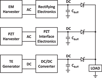
Figure 1. Triple hybrid energy harvester structure.
Download figure:
Standard image High-resolution image2.1. Rectifying electronics for EM harvester
The low resonance frequency of EM harvesters make them suitable for low frequency ambient vibrations. Figure 2 depicts the self-powered AC/DC doubler which is the modified version of the rectifier presented in [17]. The doubler circuits utilizes active diodes which are composed of a PMOS switch and a comparator that controls the switch. The active diode structure closely matches the resistive characteristics of an ideal diode, and provides low forward voltage drop during rectification. However the comparators in active diodes require a DC supply to operate. The proposed circuit includes a passive AC/DC positive quadrupler and passive AC/DC negative doubler, which generate required positive and negative DC supplies of the comparators, respectively. The passive rectifier circuits are constructed with diode connected PMOS transistors, and are fed from the same harvester. Therefore the circuit operates in a self-powered manner.
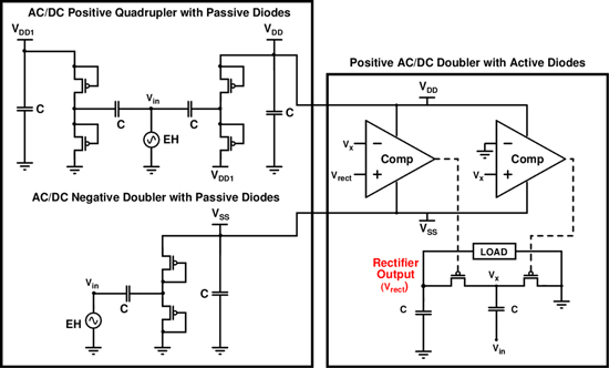
Figure 2. Self-powered rectifying electronics for low voltage EM harvester.
Download figure:
Standard image High-resolution imageOperation principle of the circuit is as follows: when the input voltage is negative and Vx potential is lower than GND, the right sided comparator turns the transistor ON and the storage capacitor between the input and Vx node is charged up to positive peak voltage of the input. When Vx goes above ground potential, the switch is turned OFF, and a positive charge is stored on the capacitor. Similarly, when the input is positive and the Vx potential is above output voltage Vrect, left sided switch is turned ON, and output storage capacitor is charged. When Vrect falls below Vx, the switch is turned OFF, and a doubled voltage is stored on the output storage capacitor. Figure 3 shows schematic diagram of the comparator circuit used to control the PMOS switches at active diodes. The comparator circuit, composed of three gain stages, has high sensitivity in order to decrease drain to source voltage of PMOS switches, which reduces the voltage drop at rectification. The comparator consists of subthreshold circuits, which enables ultra-low power operation.
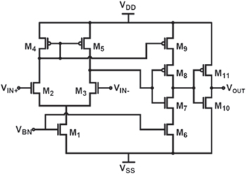
Figure 3. Comparator circuit used to control PMOS switch at active diodes.
Download figure:
Standard image High-resolution image2.2. PZT interface electronics
The proposed hybrid system includes a PZT harvester subsystem, which effectively harvests high frequency vibrations. The implemented circuit for PZT energy harvester is illustrated in figure 4. The power extraction is realized in this circuit through a set of power switches and an external inductor. Switching on the external inductor between PZT clamped capacitance and the output buffer capacitance, based on synchronous electric charge extraction (SECE) technique, enables boosting extracted power and transferring of the generated charge to the output capacitor [18].

Figure 4. Schematic of self-powered SECE harvester: (a) piezoelectric model (b) implementation of SECE (c) storage capacitance and load.
Download figure:
Standard image High-resolution imageThe idea behind the SECE scheme is to transfer the charge built up on PZT clamped capacitor to the storage capacitor in one shot, which is more efficient in weakly coupled and non-resonant systems. In this technique, the switches should be operated synchronously with the vibration of the host structure in order to maximize the power flow; hence they require precise switch control circuitry. The main drawbacks of the previously reported SECE implementations are their timing problems and input power limitation [19]. Timing problem is overcome by event-based switching through detectors and digital control. The precision of the switch control circuitry also determines the efficiency of the whole system in exploiting harvested energy. Minimum input power requirement is reduced through minimizing power losses in control switch circuitry. Besides, power efficiency is further optimized for a wide range of output voltage by decreasing dynamic losses of switch drivers.
Initially the AC voltage generated on PZT harvester is converted to positive signal through negative voltage converter (NVC). The power extraction is achieved in three phases by SECE circuit. In the first phase, all switches are turned OFF and the PZT harvester vibrates in open circuit condition. The second phase is initiated by turning ON S1 at maxima of the PZT voltage. The established resonant circuit between PZT clamped capacitor and the inductor transfers energy stored on the PZT capacitor to the inductor. The third phase starts when PZT capacitor voltage reaches zero. At this point, S1 is turned OFF, S2 and S3 switches are ON, and the stored energy on the inductor is transferred to the storage buffer capacitance, CS. This phase stays active until the inductor current reaches zero. A new energy transfer cycle is initiated by turning all switches OFF.
When the storage capacitance voltage is below the minimum required for proper operation of active components, the storage capacitor is charged through NVC and bypass circuits. As storage voltage passes the threshold voltage, synchronous power extraction is activated and bypass circuit is disabled. High power efficiency has been achieved for a wide range of output voltage by decreasing power losses in control switch circuitry and switch drivers.
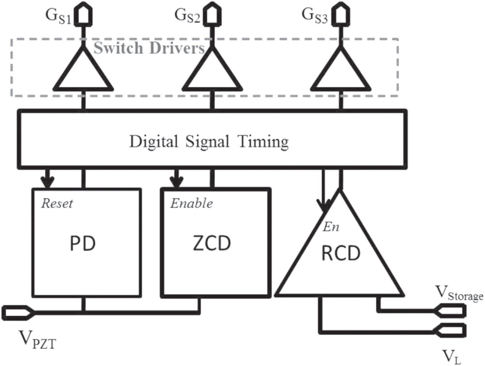
Switch control circuitry consists of detectors, a digital controller and switch drivers as shown in figure 5. All detectors are designed to dissipate minimum power to minimize power losses during the activation of the synchronous switching. A peak detector, independent from supply voltage, is implemented for maxima detection of the PZT voltage. The detector works in subthreshold region to reduce static power loss by converting PZT voltage through a series capacitor and comparing with a current-reference. Zero cross detector and reverse current detector are activated only in second and third phases, respectively. This increases the accuracy of the detection instants and saves power. The signals generated by the detectors are utilized by digital logic to time the switches. Special switch drivers are utilized for driving the power MOSFET switches to provide fast and power efficient switching.

Figure 5. Switch control circuitry.
Download figure:
Standard image High-resolution image3. Test setup
Figure 6 depicts die micrographs of the interface circuits designed and implemented in CMOS 180 nm technology. The hybrid system was tested for different load conditions with ideal input sources (signal generator and DC power supply) and vibration based energy harvester modules. Figure 7 shows the in-house EM module designed to harvest energy from low frequency ambient vibrations such as human motion. The module is composed of a cylindrical tube package, a fixed magnet at the bottom cap with 5.3 mm × 5.3 mm × 0.5 mm dimensions, and a cylindrical free moving magnet inside the tube with 10 mm diameter and 18 mm height. The fixed and free moving magnets are placed with reverse polarity hence the free moving magnet stays suspended inside the tube. The free moving magnet generates an alternating magnetic field inside the pick-up coil, which is wounded around a cavity on the tube. The magnetic field variation inside the coil generates alternating voltage on the coil according to Faraday's law of induction. Frequency characteristics of the EM harvester module when excited with 0.15 g peak acceleration is presented in figure 8. The resonant frequency of the harvester is 2.6 Hz, which is compatible with vibrations due to body motion [20].
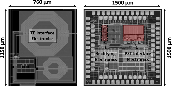
Figure 6. Die micrograph of the hybrid interface electronics in UMC 180 nm CMOS technology.
Download figure:
Standard image High-resolution image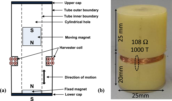
Figure 7. (a) Schematic of the EM energy harvester prototype and (b) fabricated energy harvester prototype.
Download figure:
Standard image High-resolution image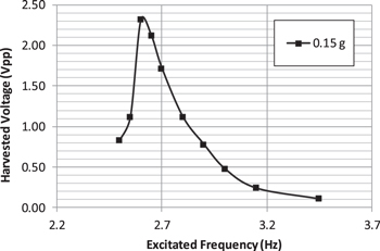
Figure 8. Peak-to-peak harvested AC voltage from EM harvester versus the vibration frequency.
Download figure:
Standard image High-resolution imageA commercially available PZT harvester module of Piezo Systems Company has been utilized for observing harvesting performance of the PZT interface. Figure 9 shows the Q220-A4-103YB PZT energy harvester of Piezo Systems company [21], and its frequency response for 0.5 g peak acceleration. The PZT harvester generates around 4 V peak-to-peak harvested voltage at 282 Hz excitation frequency and 0.5 g peak acceleration.
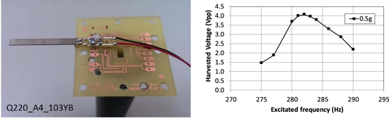
Figure 9. Q220-A4-103YB piezoelectric energy harvester and its frequency response at 0.5 g peak vibration.
Download figure:
Standard image High-resolution image4. Test results and discussion
The designed triple hybrid harvesting system was tested with different load currents and input conditions. At first the system was tested with signal generators (EM and PZT harvester inputs) and a dc supply (TE generator input). The input source of EM rectifying electronics was 5 Hz and 1.1 V peak-to-peak, whereas PZT interface electronics had an input signal of 69 Hz and 3 V peak-to-peak open-circuit voltage generated from a current source in parallel with 12 nF clamped capacitor. Both sources were observed at low level vibrations (<1 g). TE interface electronics had 0.18 V input voltage, representative of a typical TE harvester output. Figure 10 shows variation of output voltage and power of the hybrid system and stand-alone interface electronics with respect to the load resistance. The hybrid system provides more than 1 V for load resistances higher than 100 kΩ, while the stand-alone harvesting circuits are not able to reach 1 V output. The power output of hybrid and stand-alone harvesting circuits are given in figure 10(b). The hybrid system output signal is always larger than stand-alone harvesting outputs. Although sum of power generated at the output of each interface is higher than total hybrid power, the forward voltage drop and leakage currents at the Schottky diodes leads to power losses. Figure 10(c) shows power conversion efficiency variation of the stand-alone and hybrid harvesting circuits with load resistance. The efficiency of the circuit increases with decreasing load resistance. Decreasing load resistance enables higher load power at the output. Since the relative effect of power losses decreases, efficiency of the circuit increases with lower load resistance. The hybrid system efficiency is lower than stand-alone harvester efficiency due to power dissipation of off-the-shelf Schottky diodes. This can be further improved by integrating the diodes.
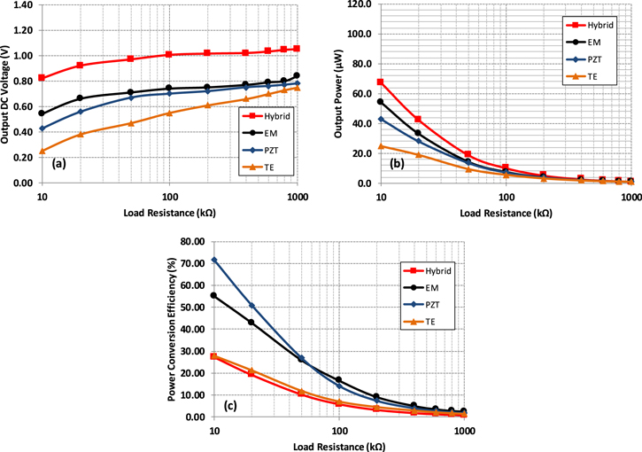
Figure 10. Variation of (a) output voltage, (b) output power and (c) power conversion efficiency with respect to load resistance of the hybrid and stand-alone energy harvesting circuits driven by signal generators.
Download figure:
Standard image High-resolution imageThe hybrid harvesting system performance was also tested with EM and PZT harvesting modules described in the previous section. The EM harvesting module was placed on the wrist of a jogger as shown in figure 11 during the tests, with 2–3 Hz of observed fundamental vibration frequency during jogging. The PZT energy harvester was excited at 282 Hz and 0.5 g peak acceleration and the TE interface electronics was supplied with 0.25 V input voltage. The hybrid harvesting system delivered more than 1.2 V output while driving load resistances higher than 50 kΩ (figure 12). This voltage and power levels could supply wearable sensors [22, 23]. The stand-alone harvesting circuits were not able to reach 1.2 V output for the given input conditions. The power output of hybrid harvester was always higher than stand-alone systems. Up to 110 μW of output power was obtained from hybrid system Moreover, at 1.2 V output the hybrid system could provide 24 μW of output power to drive the given sensors in [22, 23]. The hybrid structure can drive single supply with a maximum of 56% of the sum of output power generated by the stand-alone harvesting systems on distinct loads. This value is obtained when 10 kΩ of load resistance is connected to the output of each system. This power can be further increased by decreasing the losses at Schottky diodes and designing a smarter system with MPPT circuits. When the energy harvesting sources provide higher input power to the harvesting circuits, output voltage and power levels from the harvesting circuits are also increased. The output voltage can be stabilized by adding a regulator circuit; however the regulator block have to be designed carefully to prevent significantly increased power dissipation. The power conversion efficiency of the circuits slightly increased with the increasing input power.

Figure 11. Electromagnetic energy harvester module placed on wrist of a jogger.
Download figure:
Standard image High-resolution image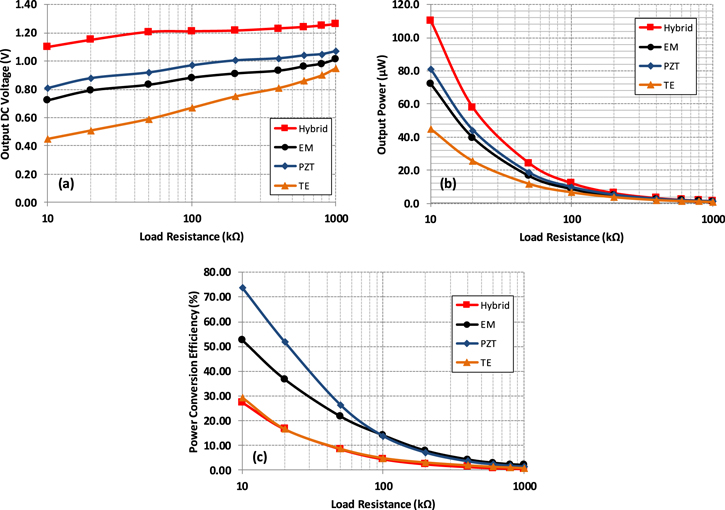
Figure 12. Variation of the (a) output voltage and (b) output power of the hybrid and stand-alone energy harvesting circuits driven by energy harvesting modules.
Download figure:
Standard image High-resolution image
5. Conclusion
In this work, a triple hybrid energy harvesting system has been realized through combination of TE, EM and PZT scavengers. The extracted cumulative energy is delivered to the target load as a single output. A cantilever PZT harvester and an in-house EM harvester have been used to extract ambient vibrations at different frequencies. An autonomous active rectifier is utilized to interface the voltage generated over the EM harvester which is mounted on the wrist of a jogger. In parallel, a self-powered SECE interface derives the energy of high frequency ambient vibration by means of the PZT harvester. In addition to vibration sources, DC power scavenged from thermal energy is boosted and transferred to the load associated with other sources. Experimental results show that the hybrid structure was able to transfer energy into a unique load. Triple hybrid harvester provides at least 1.2 V output for load resistances higher than 50 kΩ whereas stand-alone harvesting outputs are not able to attain this voltage. Moreover, the system can supply up to 110 μW of output power (24 μW @ 1.2 V) to the electrical load. The implemented system is able to simultaneously combine harvested power from three different sources while providing 56% of the maximum output of the distinct harvesting loads on the single load. Hence, this energy harvesting system has great potential to generate desired supply voltage and sufficient energy to power up sensors. It is expected that the efficiency of the hybrid system can be further increased in the future through the integration of the discrete components, and smart management. Moreover, output voltage of the system can be stabilized with an efficiently designed regulator block.
Acknowledgments
The work presented in this paper was in part supported by METU Intercampus Scientific Research Project No. BAP FEN-16-K-7.