

Abstract
The stress recovery and cyclic deformation behaviour of Fe–17Mn–5Si–10Cr–4Ni–1(V,C) shape memory alloy (Fe-SMA) strips, which are often used for pre-stressed strengthening of structural members, were studied. The evolution of recovery stress under different constraint conditions was studied. The results showed that the magnitude of the tensile stress in the Fe-SMA member during thermal activation can have a signification effect on the final recovery stress. The higher the tensile load in the Fe-SMA (e.g., caused by dead load or thermal expansion of parent structure during heating phase), the lower the final recovery stress. Furthermore, this study investigated the cyclic behaviour of the activated SMA followed by a second thermal activation. Although the magnitude of the recovery stress decreased during the cyclic loading, the second thermal activation could retrieve a significant part of the relaxed recovery stress. This observation suggests that the relaxation of recovery stress during cyclic loading is due to a reversible phase transformation-induced deformation (i.e., forward austenite-to-martensite transformation) rather than an irreversible dislocation-induced plasticity. Retrieval of the relaxed recovery stress by the reactivation process has important practical implications as the prestressing loss in pre-stressed civil structures can be simply recovered by reheating of the Fe-SMA elements.
Export citation and abstract BibTeX RIS
1. Introduction
Shape memory alloys (SMAs) are smart metals that can retrieve their shape after being deformed through an activation process which includes heating and cooling. Ni–Ti SMAs, which are the most commonly used SMAs, have different applications such as medical and aerospace devices [1, 2]. Fe–Mn–Si based SMAs have gained much attention because of their relatively low production cost and good mechanical properties [3]. Because of these favourable characteristics, Fe–Mn–Si SMAs are considered in mechanical [4] and civil engineering applications [5]. The shape memory effect (SME) in Fe–Mn–Si alloys is a result of a stress-induced forward phase transformation from austenite-to-martensite at low temperature and its reverse upon heating at higher temperatures [6]. An SMA element can be used as a pre-stressing element in civil/mechanical engineering applications when it is constrained during the activation process. There have been many studies on utilisation of SMAs for pre-stressed confinement of concrete girders [7], concrete columns [8] and steel tensile members [9].
A novel Fe–17Mn–5Si–10Cr–4Ni–1(V,C) SMA, which will be hereafter referred to as Fe-SMA, has been recently developed at Empa [10–13]. Previous works on the corrosion [14], recovery stress [11], creep/relaxation [15] and phase transformation [5] of the alloy showed its suitability for civil and mechanical engineering applications. Pre-stressed elements made of fibre-reinforced polymer (FRP) have been already proven to be very effective in increasing the performance of concrete [16, 17] and metallic [18–21] structures. However, the easy pre-stressing method of the Fe-SMA elements offers clear advantages over the complex pre-stressing techniques required for FRP composites [22, 23]. Figure 1 schematically presents the general concept of pre-stressed strengthening of a structural member (which is also called 'parent structure') using the Fe-SMA strips. The different steps of pre-straining (figure 1(a)), anchoring (figure 1(b)) and thermal activation (figure 1(c)) are illustrated. Finally, figure 1(d) shows the expected stress state in the form of compression in the parent structure and tension in the Fe-SMA strip after the activation. It has been shown in previous studies that application of a compression stress to structural members (using pre-stressed elements) can enhance the flexural capacity [24], buckling strength [18] and fatigue behaviour [25] of civil structures.
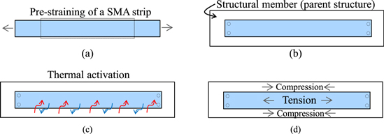
Figure 1. Application of SMA elements to strengthen a structural member. (a) Pre-straining, (b) fixing to a structural member (c) thermal activation, (d) stress state after activation.
Download figure:
Standard image High-resolution imageThe changes in the microstructure of the FE-SMA due to mechanical and thermal loading have already been studied using optical microscopy, scanning electron microscopy (SEM), electron backscattering diffraction, x-ray diffraction, in situ neutron diffraction and differential scanning calorimetry techniques [10–13, 15, 26–28]. Readers are encouraged to refer to the references for more information.
While there are studies on the phase transformation and the recovery stress of Fe-SMA (e.g., [26–30]), the mechanical behaviour of activated Fe-SMA subjected to cyclic loading has not yet been studied. This is while it is important for design assessments to acknowledge the mechanical response of the Fe-SMA after activation.
The present study first reports observations from conducted experiments for characterisation of the as-received Fe-SMA strips in terms of tensile strengths, thermal expansion behaviour and stress recovery response. Later it examines the behaviour of the activated Fe-SMA strips under cyclic loading. Moreover, this work studies the effect of a second activation on the behaviour of the Fe-SMA strips. The test results presented in this work are expected to be helpful for design of pre-stressed retrofit systems for mechanical and civil engineering applications.
2. Material
The investigated Fe-SMA in this study was received in the form of 1.5 mm thick sheets with a width of 100 mm. The production process for the sheets included induction melting and casting of large ingots under atmospheric conditions, stepwise hot pressing to a thickness of 15 mm, hot rolling to a thickness of 3 mm, solution treatment, ageing, and finally cold rolling process. More details about the manufacturing process can be found in [13].
The nominal chemical composition of the alloy is Fe–17Mn–5Si–10Cr–4Ni–1(V,C) (mass%) [27]. Figure 2 shows the microstructure of the as-received Fe-SMA etched with a solution of C2H5OH (96%)/HNO3(65%)/HCl (32%) with the ratio of 17/2/1. The alloy has a polycrystalline microstructure with an average grain size of approximately 11 μm. Some of the grains contain large bands, which are twins, while many grains contain very fine bands, which are presumably ε-martensite. The fine observed distribution of VC carbides forms large elastic strain fields which provide preferential nucleation site for the stress-induced transformation from fcc to hcp phase. The precipitates are also assumed to increase the strength of the austenite and prevent slip deformation [28]. These enhance the shape memory property and eliminate the requirement for a 'training' treatment.
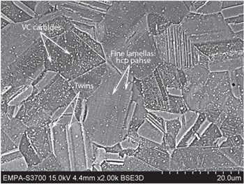
Figure 2. SEM-BSE image of the as-received Fe-SMA.
Download figure:
Standard image High-resolution image3. Experimental details
A set of dog-bone shaped tensile specimens with a gauge length of 25 mm and cross-section of 10 × 1.5 mm2 was manufactured. The dog-bone specimens were extracted longitudinal to the rolling direction of the Fe-SMA strips, using electro discharge machining. A servo-hydraulic uniaxial testing machine equipped with an induction heating system was employed for conducting of the experiments (see figure 3). A spring-loaded side-entry extensometer with a datum leg spacing of 15 mm was attached to the central part of the specimen gauge length for strain measurement. Force was monitored by the built-in load cell of the testing machine. Feedback from a type-K thermocouple (spot-welded to the centre of specimen gauge length) was used for control of the induction heating and an air cooling system for careful control of the specimen temperature. A summary of the conducted experiments is given in table 1 and further described in the followings.

Figure 3. Employed testing setup illustrating the dog-bone specimen, side-entry extensometer, thermocouple and heating/cooling systems.
Download figure:
Standard image High-resolution imageTable 1. Summary of the conducted experiments.
| Specimen | Testing detail |
|---|---|
| #1 | Uniaxial room temperature tensile testing |
| #2 | Determination of thermal expansion response |
| #3 | Pre-straining and mechanical strain-controlled thermal activation (30 °C min−1) |
| #4 | Pre-straining and mechanical strain-controlled thermal activation (2 °C min−1) |
| #5 | Pre-straining and total strain-controlled thermal activation (30 °C min−1) |
| #6 | Pre-straining and total strain-controlled thermal activation (2 °C min−1), followed by cyclic deformation (10 cycles, 2 mHz, Δε = 0.070%) |
| #7 | Pre-straining and total strain-controlled thermal activation (2 °C min−1), cyclic deformation (2 × 10⁶ cycles, 10 Hz, Δε = 0.035%) and final tensile testing |
| #8 | Pre-straining and total strain-controlled thermal activation (2 °C min−1), cyclic deformation (2 × 10⁶ cycles, 10 Hz, Δε = 0.070%), reactivation (2 °C min−1), cyclic deformation (2 × 10⁵ cycles, 10 Hz, Δε = 0.070%) and final tensile loading |
| #9 | Pre-straining and total strain-controlled thermal activation (2 °C min−1), cyclic deformation (2 × 10⁶ cycles, 10 Hz, Δε = 0.105%), reactivation (2 °C min−1), cyclic deformation (2 × 10⁵ cycles, 10 Hz, Δε = 0.105%) and final tensile loading |
3.1. Material characterisation
3.1.1. Tensile behaviour
The room temperature tensile properties of the as-received Fe-SMA were measured at a strain rate of 0.15% s−1. For strains smaller than 10%, the test was controlled based on direct feedback from the side-entry extensometer. For larger strains, because of the measurement limitation of the extensometer, the test ran under a machine crosshead displacement rate of 0.075 mm s−1 which is approximately equivalent to the strain rate of 0.15% s−1 in the gauge length. The loading continued under constant displacement rate till the final rupture of the specimen and ultimate tensile strength and elongation of the Fe-SMA were determined.
3.1.2. Thermal expansion behaviour
The thermal expansion behaviour of the as-received Fe-SMA was investigated for the temperature range of 25 °C–160 °C. The evaluation included measurement of the strain development in the specimen under a zero-stress loading condition while specimen was heated from room temperature to 160 °C and then cooled down to room temperature again. The recorded strain evolution represents the free thermal expansion/contraction behaviour of the as-received SMA. In order to remove the possible strain contribution from shape recovery of the SMA after cold rolling, the as-received specimen was heated up to 170 °C prior to the thermal strain measurement.
3.1.3. Stress recovery behaviour
The Fe-SMA specimens were first loaded to 2% tensile strain under a constant strain rate of 0.15% s−1 at room temperature. Subsequent unloading of the specimens indicated accumulation of ∼1.3% tensile pre-strain in the Fe-SMA. For thermal activation under rigid constraint, the Fe-SMA specimens were kept under constant total strain and heated from room temperature to 160 °C and then cooled down to room temperature again. For thermal activation under constant mechanical strain (εmechanical = εtotal − εthermal), a tensile strain equivalent to Fe-SMA thermal expansion was applied to the specimen during the heating, while the equivalent compressive strain was imposed to the SMA during the cooling process. For both total and mechanical strain activations, two temperature transient rates of 2 or 30 °C min−1 were examined. In order to prevent buckling of the specimens (during the early part of heating), a tensile stress of 50 MPa was applied to the specimen before the start of the activation process [11]. The activation process (i.e., heating and cooling processes) retrieved a portion of the pre-accumulated strain and recovered a significant tensile stress in the specimens.
3.2. Cyclic deformation response of the Fe-SMA after activation
Fe-SMA reinforced civil engineering structures are typically subjected to external cyclic loading, and therefore, cyclic stresses are expected to superimpose on to the recovered stress in the Fe-SMA during the service life of such structures. As the thin Fe-SMA strip has insignificant effect on the global stiffness of large civil structures, the imposed cyclic loading on the Fe-SMA is assumed to have a strain-control characteristic. Laboratory simulation of such a condition has been realised in a set of tests in this study. In these tests, after the activation process, a strain-control cyclic loading was applied to the Fe-SMA at room temperature to evaluate the mechanical response of the activated Fe-SMA subjected to cyclic loading. The evolution of stress and strain during the cyclic loading was recorded by a data acquisition frequency of 100 Hz.
The test campaign focused on two strain ranges of 0.035% and 0.070% with frequency of 10 Hz for two million cycles. The strain ranges of 0.035% and 0.070% are aimed to represent the common (service) strain ranges that are subjected to pre-stressing elements in steel [9, 31] and concrete [11] structures, respectively. The testing matrix was further complemented with two additional tests, one with a strain range of 0.105% and frequency of 10 Hz and the other with strain range of 0.070% and frequency of 2 mHz (2 × 10⁻³ Hz). The observations from the cyclic loading were exploited to understand the mechanical response of the activated Fe-SMA.
3.3. Second activation and subsequent cyclic loading
Two of the cyclic tests described in section 3.2 were chosen to be followed by a second thermal activation. At the end of cyclic loading, the specimens were kept under a constant total strain condition while were heated up to 160 °C and subsequently cooled down to room temperature. Such a second thermal activation under full constraint condition resulted in retrieval of tensile stress and an increase of the recovery stress. The tests were then continued by additional strain-controlled cyclic loading to evaluate the cyclic response of the Fe-SMA after the second activation.
3.4. Final tensile testing
Finally and after the end of cyclic loading, the specimens were loaded up to failure to determine the effect of the activation process and cyclic deformation on tensile strength and elongation of the Fe-SMA. The tensile loading was conducted under a constant strain rate of 0.15% s−1 for strains smaller than 10% and continued up to failure under machine crosshead displacement rate of 0.075 mm s−1 (∼ = 0.15% s−1). The tensile strength and elongation of the Fe-SMA specimens were recorded.
4. Results and discussion
4.1. Tensile testing
Figure 4 presents the observations from uniaxial tensile testing of the as-received Fe-SMA strips. The determined values of elastic modulus, limit of proportionality (σ0.01), 0.2% proof stress (σ0.2), tensile strength and elongation are indicated in the figure. The early inelastic response, which can be observed in figure 4, is assumed to be due to the austenite-to-martensite phase-transformation rather than dislocation induced plasticity [12]. The ultimate tensile strength and elastic modulus of 1015 MPa and 173 GPa determined in this study are larger and smaller than the 993 MPa and 200 GPa observed in [12], respectively.

Figure 4. Room temperature tensile behaviour of the as-received Fe-SMA.
Download figure:
Standard image High-resolution image4.2. Thermal expansion behaviour
The thermal expansion behaviour of the Fe-SMA material in an austenitic state has been illustrated in figure 5 and can be given by:
where θ is the temperature in degree Celsius. As expected, the thermal expansion of the as received Fe-SMA with an austenite structure is similar to that of other austenitic steels.
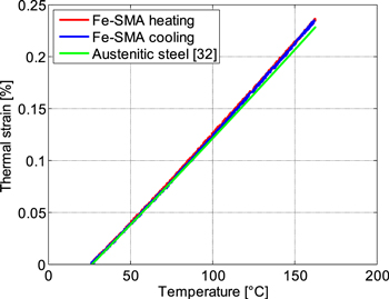
Figure 5. Comparison between the thermal expansion behaviour of the as-received Fe-SMA in this study and that of a typical austenitic stainless steel [32].
Download figure:
Standard image High-resolution image4.3. Stress recovery behaviour
The Fe-SMA recovered stress after the thermal activation process depends on the pre-straining and thermal activation conditions. Lee et al [27] have investigated the influence of different elastic restraints on the formation of the recovery stress in Fe-SMAs. Their observations have shown that the recovery stress is maximum when the Fe-SMA element is fully constrained by a parent structure with infinite stiffness (i.e., rigid restraint) during the activation process. The recovery stress, however, reduces if the parent structure has a finite stiffness (i.e., elastic restraint).
By assuming that a Fe-SMA pre-stressing element is anchored to a very stiff parent structure (e.g., see the structural member shown in figure 1), the activation process is under a rigid restraint condition (i.e. total strain-control) provided that the temperature of the parent structure does not change during the activation process. However, for the heating condition in which the temperature of both the Fe-SMA element and the parent structure simultaneously changes during the temperature transients, the activation is not any more under a constant total strain condition and is affected by the thermal expansion behaviour of the parent structure. Therefore, for the case where both the Fe-SMA element and the parent structure experience an identical heating and cooling history (e.g. homogeneous temperature distribution), the Fe-SMA undergoes a total tensile and compressive strain during heating and cooling processes, respectively (Δεtot = Δεth(parent structure)). Provided that both the Fe-SMA element and the parent structure have an identical thermal expansion coefficient, the activation takes place under constant mechanical strain (Δεmech = Δεtot − Δεth = 0 → Δεtot = Δεth).
Figures 6(a) and (b) present the observed stress recovery behaviour of the pre-strained Fe-SMA during activation under total and mechanical strain-control for two different temperature transient rates. For the tests with mechanical strain-controlled activation, the total strain during the thermal transient varies based on the relationship given by equation (1).

Figure 6. (a) Stress as a function of the total strain during pre-straining and different thermal activation strategies. (b) Recovered stress in the Fe-SMA strip as a function of temperature for different thermal activation strategies.
Download figure:
Standard image High-resolution imageThe presented results in figure 6 show that both temperature transient rates result in approximately identical final recovery stress values. Furthermore, a comparison between the recovery stresses achieved by different activation strategies indicates that the final recovery stress is higher when the activation is under total strain-control. For mechanical strain-controlled activation, a larger recovery stress is formed during the heating process compared to that for total strain-controlled activation. During the cooling process, a substantial stress recovery is achieved for activation under total strain-control, while no further stress increase was observed for mechanical strain-controlled activation. It is therefore interesting to see that the finally recovered stress under total strain-control is almost twice that developed under mechanical strain-control. This observation implies that activation of the Fe-SMA element while it is subjected to some extent of tensile stress (e.g., due to thermal expansion of the parent structure or dead-loads) will result in a decreased final recovery stress. In the following, more details about activation under total and mechanical strain-controlled conditions are given.
For total strain-controlled activation, the stress variation during the thermal transient is a result of two simultaneous phenomena of phase transformation and thermal expansion/contraction. At the beginning of heating and below 35 °C, the dominance of thermal expansion over the phase transformation effect reduces the stress in the Fe-SMA. During further heating, the phase transformation is more dominant and higher stresses are developed. More significant stress development is observed during the cooling phase where thermal contraction also helps to increase the stress. The decreasing slope of stress increase during cooling at lower temperatures in figure 6(b) is most likely due to time-dependent relaxation and to some extent of austenite-to-martensite phase transformation.
Regarding the activation under mechanical strain-control, based on [27], the main factor determining the final recovery stress is the amount of martensite that transforms back to austenite during the heating process and the induced strain. The applied strain during the heating process of the activation was fully compensated during the cooling phase (Δεtot = Δεth) and therefore does not directly influence the final recovery stress. Lee et al [12] have proposed a stress–temperature phase diagram giving estimations for the austenite start, austenite finish and martensite start temperatures (As, Af and Ms lines respectively). A schematic of such a stress–temperature phase diagram is presented in figure 7 which shows that the As temperature increases with increase of the stress level. From figure 6(b), a stress level of approximately 50 MPa and 100 MPa were respectively generated under total- and mechanical strain-control during the heating process at θ = 60 °C (with 2 °C min−1). Points A and B in figure 7 represent these two stress–temperature coordinates. It can be seen that while the reverse transformation is expected to have already started under total strain-control (point A), no martensite-to-austenite phase transformation is expected to occur for the specimen under mechanical strain-control at 60 °C (point B).

Figure 7. Scheme of the stress–temperature phase diagram including As, Af and Ms lines [12]. Coordinates A and B put into perspective the material phase state during total and mechanical strain controlled activation process during heating at T = 60 °C, respectively.
Download figure:
Standard image High-resolution imageDuring heating, and for temperatures higher than 60 °C, some extent of reverse phase transformation (martensite-to-austenite) takes place for the specimen activated under mechanical strain-control. It can be shown that for all temperatures, total strain-control results in lower stress levels which are closer to the Af line. The latter then leads to a larger extent of martensite-to-austenite phase transformation which consequently gives higher final recovery stresses after cooling. Note that the aim of presenting figure 7 is only to qualitatively show the effect of stress level during the activation process on the magnitude of the reverse phase transformation, and more details regarding the methodology for determination of the As, Af and Ms lines are given in [12].
This observation has important practical implications. It can be concluded that for Fe-SMA pre-stressing elements which are anchored to structural members, employment of a heating methodology that only increases the temperature of the Fe-SMA element and not the parent structure enhances the final obtained recovery stress. Passing a high electrical current through the Fe-SMA element can therefore be considered as an effective methodology for thermal activation of the Fe-SMA. Rapid heating techniques such as electrical resistance heating prevent any significant heat transfer to the parent structure, minimise thermal strain development, and therefore lead to a higher recovery stress in the Fe-SMA element. Furthermore, it can be concluded that activation of the Fe-SMA elements under high stress levels (e.g., due to dead-load) will result in a reduced final recovery stress.
The values of the recovery stress in the present study are between 360 and 370 MPa. These values are consistent with the results of previous studies (e.g., [11, 12, 27]) on activation of the Fe-SMA that have also employed a fully constrained thermal activation condition (i.e. total strain-controlled) with a heating rate of 2 °C min−1. Total strain-controlled thermal activation has been considered in the following for evaluation of the effect of cyclic loading on the mechanical response of the Fe-SMA.
4.4. Cyclic response of the Fe-SMA strips after activation
A set of 2% pre-strained Fe-SMA specimens were activated in total strain-control (with a temperature transient rate of 2 °C min−1) and were then subjected to cyclic loading. Figure 8 presents the observed initial stress–strain response of the activated Fe-SMA for different applied strains and strain rates. The early elastic deformation response demonstrates a modulus of 173 GPa which is identical to that of the as-received material. The start of nonlinear behaviour is dependent on the strain rate and advances with decreasing strain rate. Importantly, as shown in figure 9, such nonlinear deformation behaviour is responsible for a decrease in the subsequent recovery stress (i.e. after unloading, see σr,1 in figure 9). The amount of recovery stress loss increases with increasing loading strain and decreasing strain rate (i.e. lower frequencies).

Figure 8. The mechanical response of the activated Fe-SMA under tensile loading (σr = ∼360–370 MPa and εr = ∼1.3% are stress and strain values at the end of thermal activation).
Download figure:
Standard image High-resolution image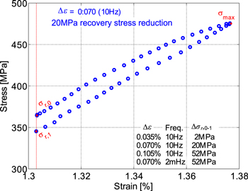
Figure 9. Decrease of recovery stress due to the first loading and unloading cycle (0.070%, 10 Hz) after activation of the Fe-SMA (inset: recovery stress reduction after first loading cycle for different conditions).
Download figure:
Standard image High-resolution imageRepeating loading and unloading cycles further decreases the residual recovery stress in the Fe-SMA. Figure 10 presents the evolution of the observed maximum stress and recovery stress (i.e. minimum stress) for the first 10 cycles of deformation involving different strain ranges and frequencies. Figure 11 illustrates evolution of the residual recovery stress for the Fe-SMA for the different examined cyclic loading conditions up to two million loading cycles. It is observed that of the recovery stress reduced with cycle number at a decreasing rate and the reduction is more significant for cyclic loading conditions with larger strain ranges. Nevertheless, for the two strain ranges of 0.035% and 0.070%, which are relevant for service loading conditions [9, 11, 31], the recovery stress after two million cycles remained above 285 MPa.
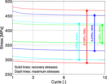
Figure 10. Evolution of the recovery stress and the maximum stress in the activated Fe-SMA for the first ten load cycles for different strain ranges and frequencies.
Download figure:
Standard image High-resolution image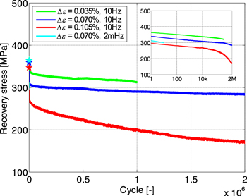
Figure 11. Relaxation of the recovery stress due to cyclic loading of the activated Fe-SMA for different strain ranges and frequencies.
Download figure:
Standard image High-resolution imageThe observed loss of the recovery stress is attributed to cyclic-deformation-enhanced stress relaxation due to time-dependent inelastic deformation. As discussed in the next section, this inelastic deformation is mostly due to austenite-to-martensite phase transformation rather than dislocation-induced plasticity. Such a decrease in the recovery stress is important and should be taken in to account in design assessments of SMA pre-stressed structures.
4.5. Second activation and subsequent cyclic loading
Relaxation of recovery stress during cyclic loading has been discussed in the previous section. The following examines employment of a second thermal activation process for retrieving at least a part of the relaxed recovery stress. For the tests with cyclic strain ranges of 0.070% and 0.105%, which showed considerable amounts of relaxation after two million cycles, the specimens were held under constant total-strain after the last cycle (at a strain level of ∼1.3%). Similar to the first thermal activation process, the specimens were then heated to 160 °C and cooled down to room temperature (at a rate of 2 °C min−1).
Figure 12 illustrates evolution of the stress in the Fe-SMA as a function of temperature during the second activation process. As can be seen, during the early stage of reheating and up to 70 °C, the stress decreases substantially due to thermal expansion. With increasing temperature, the stress–temperature curve becomes less steep which is assumed to be a result of the SME and martensite-to-austenite transformation. During the cooling phase, the stress increases mainly due to thermal contraction. Figure 12 demonstrates that the second activation could effectively enhance the recovery stress in the Fe-SMA after cyclic deformation. A comparison of the obtained recovery stresses after the first and second activations indicates that the second activation retrieves a considerable portion of the recovery stress which had been relaxed due to cyclic loading. This phenomenon is more pronounced in particular for the specimen loaded for the strain range of 0.070% where the recovery stress at the end of the second activation is very close to that of the first activation. This indicates an almost full retrieval of the relaxed recovery stress and implies that the stress relaxation and accumulation of the inelastic strain during the cyclic loading are mainly due to the austenite-to-martensite forward transformation, and therefore recoverable. Figure 13 shows the complete stress and temperature histories for specimen #8, including pre-straining, first activation, first cyclic loading, second activation, second cyclic loading and the final tensile loading.
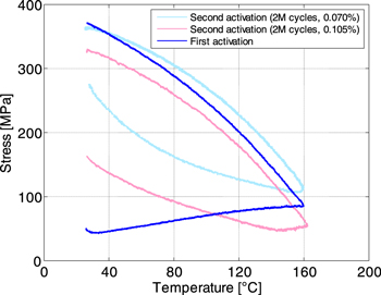
Figure 12. Comparison of stress recovery behaviour during first and second thermal activations (after two million loading cycles).
Download figure:
Standard image High-resolution image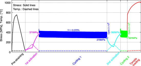
Figure 13. Complete stress and temperature histories for specimen #8. The diagram includes different test steps of pre-straining, first activation, first cyclic loading, second activation, second cyclic loading and the final tensile loading.
Download figure:
Standard image High-resolution imageThe retrieval of relaxed recovery stress by a second activation has important implications for practical employment of the Fe-SMA as pre-stressing elements in civil engineering applications. Such reactivation, for example, can retrieve the pre-stressing force in a strengthened structure, when the SMA element has lost some of its pre-stressing force due to cyclic loading, relaxation or accidental overloading.
Figure 14 compares the behaviour of the Fe-SMA strips subjected to cyclic loading after the first and the second thermal activations. The observations indicate almost identical patterns in the stress relaxation behaviour of the Fe-SMA after first and second activations.
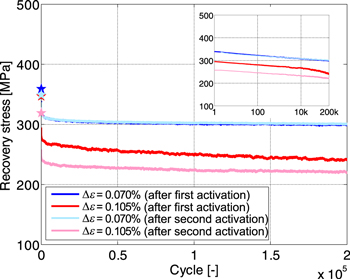
Figure 14. Relaxation of recovery stress due to cyclic loading with different strain ranges for Fe-SMA after first and second thermal activations.
Download figure:
Standard image High-resolution image4.6. Final tensile loading
The last step for most of the conducted experiments in this study was applying an increasing tensile load to the specimens up to the failure. Figure 15 shows the tensile behaviour of the as-received specimen and those which were activated and subjected to cyclic loading. The results indicate that neither thermal activation nor cyclic loading (up to 2.2 million cycles) have induced any damage in the Fe-SMA to deteriorate the tensile response.

Figure 15. Tensile behaviour of the as-received Fe-SMA in comparison with those after activation and cyclic loading.
Download figure:
Standard image High-resolution image
5. Concluding remarks
This study examined the mechanical behaviour of a novel Fe-SMA under different loading conditions. The following summarises the concluding remarks:
- The as-received Fe-SMA strips showed outstanding tensile strength and elongation of >1000 MPa and >55%, respectively. These values were not affected by activation and subsequent cyclic loading.
- After 2% pre-straining, thermal activation of Fe-SMA under a fully constraint condition to maximum temperature of 160 °C recovered a stress of 360–370 MPa. The recovered stress for activation under mechanical strain-control (εmechanical = εtotal − εthermal) was significantly lower. It was concluded that the tensile stress level on the Fe-SMA element during activation process should be minimised in order to obtain higher recovery stresses.
- The recovery stress partially relaxes when the activated Fe-SMA is subjected to cyclic loading conditions. The relaxation is more pronounced for larger strain ranges and lower strain rates.
- A significant part of the loss in the recovery stress, which occurs during cyclic loading, is retrieved when the Fe-SMA is thermally reactivated. This finding has important practical implications and provides a possible solution for restoring the pre-stressing force of structures, which have lost a substantial portion of their pre-stressing force due to relaxation, cyclic loading or overloading, simply by reheating the Fe-SMA elements to the activation temperature.
Acknowledgments
The authors would like to acknowledge the support from the re-fer AG Company in Switzerland for providing the Fe-SMA strips for this study.