

Abstract
Electromagnetic clutches have been widely used in underactuated lightweight manipulator designs as a coupling mechanism due to their advantages of fast activation and electrical controllability. However, an electromagnetic clutch consumes electrical energy continuously during its operation. Furthermore, conventional electromagnetic clutches are not fail-safe in unexpected power failure conditions. These factors have a significant impact on the energy efficiency and the safety of the design, and these are vital aspects for underactuated lightweight manipulators. This paper introduces a bistable electromagnetic coupling mechanism design, with reduced energy consumption and with a fail-safe mechanism. The concept of a bistable electromagnetic mechanism consists of an electromagnet with two permanent magnets. The design has the capability to maintain stable mechanism states, either engaged or disengaged, without a continuous electrical power supply, thus enhancing fail-safety and efficiency. Moreover, the design incorporates the advantages of conventional electromagnetic clutches such as rapid activation and electrical controllability. The experimental results highlight the effectiveness of the proposed mechanism in reducing electric energy consumption. Besides this, a theoretical model is developed and a good correlation is achieved between the theoretical and experimental results. The reduced electric energy consumption and fail-safe design make the bistable electromagnetic mechanism a promising concept for underactuated lightweight manipulators.
Export citation and abstract BibTeX RIS
1. Introduction
The reduction in weight and the building of lightweight manipulators has created significant attention among researchers and robot manufacturers due to high demand, as well as their distinct features and significant benefits. Lightweight manipulators consume less energy as the weight is reduced. Besides this, lightweight manipulators have a higher payload to weight ratio in comparison to conventional devices [1]. Actuators are the major component, and they significantly contribute to the weight of the manipulator [1–3]. Therefore, the general strategy for designing lightweight manipulators involves designing them with reduced actuators or locating the actuators and heavy joint components at the base. Reducing the number of actuators has significant benefits such as lowering energy consumption, making the design more compact, and reducing the weight and cost [4, 5]. A substantial number of motors increases the mass, cost and demand for more power. The distinct benefit of minimising the number of actuators used advocates the implementation of the concept of reducing the number of motors used in lightweight manipulators.
To achieve this, manipulator designers can replace the motors installed at each degree of freedom with the clutches. However, a central motor is kept to maintain the distribution of energy to the joints through gear trains or through tendons. The clutches installed control the supply of energy to the joints. The manipulator joint motion is manoeuvred by controlling the energy supply to the passive joints and engaging and disengaging the clutches [6]. Engaging the clutch is analogous to switching the state of the actuator 'on', and similarly, disengaging it leads to an 'off' state. This leads to a reduction of the number of motors in the manipulator design. Over the years, researchers have developed manipulator designs with reduced amounts of actuators. The majority of designs have incorporated electromagnetic clutches due to the benefits of fast activation, moderate torque density and electrical controllability [7–11].
Apart from the benefits, the major drawback of a conventional electromagnetic clutch is that power needs to be supplied throughout operation. The power supply is used for the excitation of the electromagnetic coil. The electromagnet provides the holding force required to maintain the engage state of the clutch. Therefore, the power supply can only be terminated during the disengaging of the clutch [12–14]. As such, electromagnetic clutches consume large amounts of energy during clutch operation. Furthermore, disengagement of the clutch due to unexpected power failure is another drawback [15, 16]. According to the EU directive 2006/42/EG clause 1.2.6, the drive must not disengage in the case of a power failure [17]. The directive enhances the safety of the system in a situation when unexpected power failure occurs. However, a conventional electromagnetic clutch cannot remain in an engaged state without a continuous power supply. Hence, the implementation of a conventional electromagnetic clutch reduces the safety of the system. Moreover, the dissipation of heat energy from the electromagnetic coil due to a continuous power supply is another disadvantage. Therefore, designing an energy efficient and safe mechanism is essential for underactuated manipulators. Furthermore, this will enhance the fundamental design requirements of underactuated lightweight manipulator design such as safety and efficiency. In the recent years W Cai et al developed a bistable electromagnetic clutch unit for an electric vehicle to reduce its energy consumption [18, 19]. However, the design was primarily developed for electric vehicle wheel drive applications [18–20]. Specifically, the clutch was mainly developed for the function of maintaining the connection between the electric vehicle wheel drive hub and the motor [19–21]. Apart from that, companies such as Mönninghoff, KEB, Electroid and EIDE have introduced bistable clutches and bistable brake designs for applications such as air-conditioning compressors, electric doors, wheelchairs, etc [22–25]. However, these commercial designs utilise power supplies for periods of 100 ms to 1000 ms during the engaging and disengaging operations [22–25]. Energy consumption of the clutch or the brake decreases with the reduction of the power supply time. Therefore, by minimising the power supply time, energy consumption can be further reduced enhancing energy efficiency. Moreover, coil springs are incorporated in the commercial bistable clutch and brake designs for the disengaging process, reducing the robustness [22, 24]. Systems integrated with coil springs have low robustness due to the wear and degrading of the springs [26–28].
The aim of this paper is to present the design of an energy efficient and safe bistable electromagnetic coupling mechanism. The proposed mechanism is capable of maintaining both the engage and disengage states without a continuous power supply. Therefore, the proposed design reduces energy consumption. In the proposed design, power is only consumed for a period of 12 ms during the engaging and disengaging operations. Therefore, in the proposed design the power consumption time period is minimised considerably. Furthermore, the proposed mechanism prevents the dissipation of heat energy from the electromagnetic coil due to the continuous flow of current. The mechanism can be activated and deactivated by applying a current pulse. The change of direction of the current flow varies the state of the mechanism. In addition, the proposed mechanism has a fail-safe design. The design can maintain the engage or disengage state in the absence of a power supply using the bistable permanent magnetic mechanism. The mechanism state cannot be varied until a further current pulse is applied. Therefore, the existing state can be sustained in sudden power failure conditions; thus, the design offers increased safety. In addition to this, coil springs are not incorporated in the proposed mechanism, thus enhancing the robustness. The proposed design has the potential to provide a safe and energy efficient mechanism for underactuated lightweight manipulators.
The rest of the paper is arranged as follows. The mechanical design of the mechanism is explained in detail in section 2. Section 3 includes the operation principle of the bistable mechanism. The theoretical model of the proposed design is developed for the engaging and disengaging of the mechanism. The developed theoretical model is presented in section 4. Section 5 includes the experimental results of the mechanism, which includes an electrical energy consumption analysis and the validation of the theoretical model developed. Finally, a conclusion is drawn in section 6.
2. Mechanical design of the bistable coupling mechanism
The design consists of two segments, namely segments A and B. Segment A contains the electromagnet used in the mechanism and segment B contains the permanent magnets and the sliding disk. In segment A, the rotor transfers the rotational motion to the load when the mechanism is engaged. The load is connected to the extended segment of the rotor, as shown in figure 1. The bearing mounted between the electromagnet casing and the rotor maintains the stable position of electromagnet allowing the rotor motion. Similarly, the bearing mounted between the rotor and the housing of the proposed design prevents the rotation of the casing of the mechanism along with the rotor. Segment B of the design consists of a sliding disk and an armature. At the centre of the sliding disk, a disk type NdFe35 permanent magnet (L) with a holding force of 33 N is mounted. The diameter and the thickness of the magnet are 20 mm and 3 mm respectively. The permanent magnet provides the holding force required to maintain the engaged state. Thus, the requirement of a continuous power supply is eliminated. Similarly, a disk type NdFe35 permanent magnet (S) with a holding force of 2.9 N is attached to the other side of the disk, which helps to hold the disengaged state. The permanent magnets are 10 mm in diameter and 5 mm thick. In the design, grooves are fabricated on the plate of segment B to couple it with the teeth fabricated in the sliding disk. Furthermore, the shafts mounted to the armature function as a guide for the sliding disk's linear motion. The bearings are connected between the armature and the casing. The external and internal view of the constructed bistable coupling mechanism are shown in figures 2(a) and (b) respectively. The design parameters of the proposed mechanism are also presented in table 1.

Figure 1. A schematic drawing of the cross-section view of the proposed bistable mechanism.
Download figure:
Standard image High-resolution image
Figure 2. (a) A constructed view of the bistable coupling mechanism; (b) an internal view of the bistable coupling mechanism.
Download figure:
Standard image High-resolution imageTable 1. Design parameters.
| Definition | Value |
|---|---|
| Permanent magnet S (NdFe35) diameter/thickness | 20 mm/3 mm |
| Permanent magnet L (NdFe35) diameter/thickness | 10 mm/5 mm |
| Air gap length | 10 mm |
| Number of windings (electromagnet) | 700 |
| Sliding disk diameter/thickness | 50 mm/10 mm |
3. Operation principle
The proposed bistable coupling mechanism has two states, namely engage and disengage. The state varies with the movement of the sliding disk. The state of the mechanism can be changed by switching the direction of the current supply to the electromagnet. The electromagnet will generate an attraction or repelling force on the permanent magnet (L) fixed to the disk with respect to the direction of the current supply. This force will result in the sliding of the disk, changing the state of the proposed design. Figures 3(a) and (b) show the magnetic field distribution of the coupling mechanism in the two states engaged and disengaged. The functionality of the mechanism with the respective forces is explained in the following section.
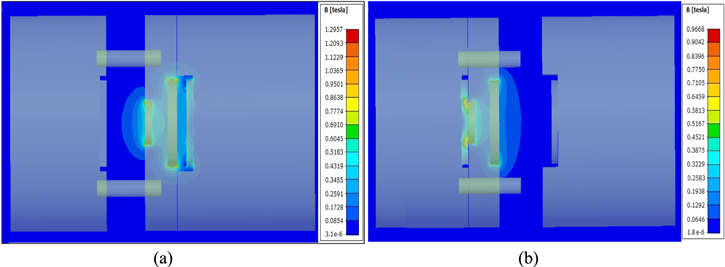
Figure 3. (a) The magnetic flux density distribution in the engaged state; (b) the magnetic flux density distribution in the disengaged state.
Download figure:
Standard image High-resolution image3.1. Engaged state
The bistable mechanism remains in a disengaged state prior to varying the state to engage. The sliding disk remains stable in segment A of the mechanism. The force FSPM generated between the ferromagnetic plate and the permanent magnet (S) prevents the motion of the disk towards the rotor, as shown in figure 4(a). In the design, a permanent magnet (L) is in a fixed position with the north pole of the magnet towards the electromagnet. To move the disk towards the rotor, an additional force should be applied to the sliding disk to produce a resultant force in the direction of motion. Therefore, an attractive force should be generated between the disk permanent magnet (L) and the electromagnet. As such, the electromagnet is energised to form a south pole at the surface of the electromagnet. This creates an attractive force FEPM between the permanent magnet (L) and the electromagnet, producing a resultant force on the disk. The resultant force initiates the motion of the disk towards the rotor at the instance the electromagnet is energised. When the disk reaches the rotor, the power supply can be terminated. The force generated between the permanent magnet (L) and the ferromagnetic plate maintains the engaged state with the absence of an external power supply, as shown in figure 4(b).

Figure 4. (a) The instance before the sliding disk moves from the disengaged state to engaged, when the electromagnet is energised. (b) The sliding disk after engaging and the electromagnet is de-energised.
Download figure:
Standard image High-resolution imageThere is an attraction force between the permanent magnet (S) and the ferromagnetic plate. However, in the engaged state, the FSPM force is zero. Due to the increase of distance between the ferromagnetic plate and the permanent magnet (S), the flux distribution between the permanent magnet (S) and the ferromagnetic plate reduces. In the engaged state, there is no flux distribution between the permanent magnet (S) and the ferromagnetic plate. As such, in the engaged state the FSPM force becomes zero. The flux density, figure 3(a), also shows that there is no flux distribution between the permanent magnet (S) and the ferromagnetic plate in the engaged state. As such, the current supply can be terminated at the instance the disk contacts the rotor. Therefore, the disk remains engaged until the electromagnet is energised in the reverse direction.
3.2. Disengaged state
The state can be switched from engaged to disengaged by powering the electromagnet in the reverse direction. The electromagnet polarity can be varied by switching the direction of the current supply forming a north polarity. When the current supply is reversed, a repulsive force FEPM is generated between the permanent magnet (L) and the electromagnet. As a result, a force is generated on the disk, as shown in figure 5(a). Due to the creation of the resultant force, the disk disengages and slides towards the armature, switching the state of the mechanism to disengaged. An attraction force is formed between the permanent magnet (S) and the embedded ferromagnetic plate. This attraction force FSPM maintains the disengaged state without an external energy supply, as shown in figure 5(b). Therefore, when the disk reaches the armature, the current supply can be terminated. Similar to the engaged state, figure 3(b) shows that there is no flux distribution between the permanent magnet (L) and the ferromagnetic plate in the disengaged state. Therefore, in the disengaged state, the force FLPM becomes zero due to the increase of distance between the ferromagnetic plate and the permanent magnet (L). As such, the sliding of the disk towards the rotor is prevented until an external force is applied by the electromagnet.
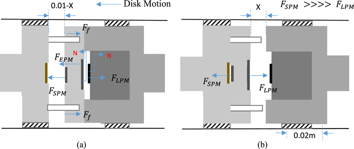
Figure 5. (a) The instance before the sliding disk moves from the engaged state to disengaged when the electromagnet is energised. (b) The sliding disk after disengaging and the electromagnet is de-energised.
Download figure:
Standard image High-resolution image4. Theoretical model
The theoretical model of the proposed bistable mechanism is presented in this section. The engaging and disengaging mechanisms of the sliding disk with the respective forces are shown in figures 4(a) and 5(a). The engaging and disengaging of the coupling mechanism is controlled by varying the direction of the force FEPM generated between the electromagnet and the permanent magnet (L), as described in the previous section. The magnetic force FEPM represents the force generated by the electromagnet on the permanent magnet (L) when energised. The magnetic force FEPM can be expressed as [29–31]:

where V, M and ∇ B are the volume of the permanent magnet, the magnetisation of the permanent magnet and the gradient of the magnetic field of the electromagnet respectively. The ∇ symbol represents the gradient operator. The computation of each component of equation (1) is performed using a sub-set of equations. The components M (magnetisation of the permanent magnet) and V (volume of the permanent magnet) are calculated as:


where Br corresponds to the magnetic remanence and is 1.30 T. The value of μm is 13.811 × 10⁻⁷, and corresponds to the permeability of the NdFe35 magnet. In equation (1), V represents the volume of the permanent magnet. The value of V is computed using the equation of volume of a disk. The final component of equation (1) is the gradient of the magnetic field of the electromagnet (∇B) [32]. The calculation of ∇B is explained in the following section.
The magnetic field generated by an electromagnet can be described by Biot–Savart's law [33]. The magnetic field generated by a single loop coil carrying a current of I at a distance X from the centre of the circular coil can be derived using the aforementioned law, as given below [34, 35]:

where μ0 and r represent the permeability of free space and the radius of a coil with a single turn respectively. X corresponds to the distance from the centre of the coil to the point where the magnetic field is computed, and I is the current flowing through the coil. From equation (4), the magnetic field generated from a circular coil with N number of loops carrying a steady current I can be expressed as:

where N represents the number of turns in the coil. Finally, the gradient magnetic field is calculated by computing the first order derivative of equation (5). The first order derivative of equation (5), which corresponds to the gradient magnetic field, is expressed as:

Finally, the magnetic force generated on the permanent magnet by the electromagnet FEPM is obtained using equations (1) to (6). The dry friction force Ff that forms on the disk can be obtained from equation (7). The dry friction force is obtained as:

A range of magnetic attraction force values with respect to the distances is obtained for each magnet from the magnet manufacturing company. Subsequently, the curve fitting method is applied for the computation of equations (8) and (9). The relationship of the force FLPM with respect to the distance can be obtained using equation (8). Similarly, equation (9) describes the relationship of the force FSPM with respect to the distance of the permanent magnet (S). The equations are as given below:


.In equation (9), Xs represents the distance between the permanent magnet (S) and the ferromagnetic plate. Similarly, XL represents the distance between the permanent magnet (L) and the ferromagnetic plate.
Finally, the theoretical model of the proposed bistable mechanism for the two states engaging and disengaging is derived as:


where m is the total mass of the disk, including the two permanent magnets embedded. Ff represents the dry friction force between the disk and the guide.  and
and  represent the velocity and the acceleration of the disk. Furthermore, X represents the distance between the surface of permanent magnet (L) and the surface of the electromagnet, as shown in figure 5(b). The distance varies with the motion of the sliding disk. The value of X ranges from 0 to 0.01 m, and the disk attains a maximum displacement of 0.01 m in the disengaged state and a minimum of 0 m in the engaged state.
4.1. Control circuit
The bistable coupling mechanism engaging and disengaging is controlled via a control circuit. Two transistors (TIP120) and a double pole double touch (DPDT) relay are used to control the direction of current flow and to switch the power supply 'on' and 'off'. Figure 6 shows the control circuit design. Varying the direction of current flow to the mechanism changes its state. To vary the direction of current flow, the base current of transistor A is varied via a microcontroller. The activation of transistor A energises the DPDT relay resulting in the engagement of the mechanism. Similarly, the deactivation of transistor A de-energises the DPDT relay, resulting in the disengagement of the proposed design. Transistor B controls the power supply to the mechanism, switching the current supply 'on' or 'off' in the DPDT relay, after the mechanism is engaged or disengaged. This results in the current supply being switched 'on' or 'off' in the proposed mechanism. During the engaging process, the current flows to the bistable coupling for 12 ms, whereas in the disengaging process it flows for 12 ms. Figure 7 presents the functionality of the circuit in a flowchart.
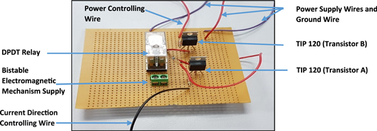
Figure 6. Bistable electromagnetic coupling mechanism control circuit.
Download figure:
Standard image High-resolution image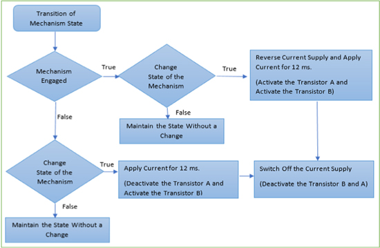
Figure 7. Flowchart presenting the operation of the control circuit.
Download figure:
Standard image High-resolution image5. Results and discussion
This section presents the experimental results and the analysis performed on the bistable electromagnetic mechanism. The time consumed during the engaging and disengaging of the mechanism is investigated experimentally, and the energy consumption of the mechanism during the operation is also analysed experimentally. The experimental setup used for the time measurement of the engaging and disengaging process is as shown in figure 8.
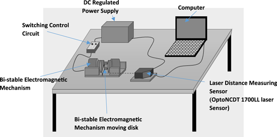
Figure 8. A schematic diagram of the experimental setup.
Download figure:
Standard image High-resolution imageThe time taken for the sliding disk motion from the armature to rotor and from the rotor to the armature corresponds to the engaging and the disengaging time respectively. Therefore, the sliding disk motion with respect to time was analysed in the engaging and disengaging scenarios. In the experimental setup, an OptoNCDT 1700LL laser distance measuring sensor was used to measure the displacement of the disk with respect to time. The output of the laser sensor was connected to a computer for the recoding and analysis of the data. Finally, the theoretical model of the proposed design was analysed with the experimental results for validation. Figure 9 shows a comparison of the experimental and theoretical displacement of the disk during the engaging process with respect to time. Similarly, figure 10 shows a comparison of the experimental and theoretical displacement with respect to time during the disengaging of the mechanism.
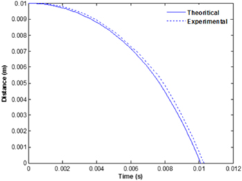
Figure 9. A comparison of the experimental and theoretical displacement of the disk with respect to time during the engaging operation.
Download figure:
Standard image High-resolution image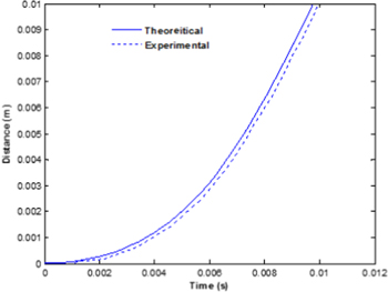
Figure 10. A comparison of the experimental and theoretical displacement of the disk with respect to time during the disengaging operation.
Download figure:
Standard image High-resolution imageFrom figure 9 it can be observed that the total theoretical time and the experimental time taken to engage is 0.0101 s and 0.0113 s respectively. The percentage difference between the theoretical and the experimental results is about 11.8%. Therefore, in general, the experimental results demonstrate a good correlation with the theoretical model. Similarly, the total time taken to disengage in the theoretical and experimental scenarios is 0.0091 s and 0.0101 s respectively. Therefore, in both scenarios, the experimental and theoretical results are in good agreement.
To analyse the energy consumption of the mechanism, the current and the voltage use of the proposed design were measured. Figure 11 shows the experimental setups used for the current and voltage measurement respectively. An ACS756 Hall effect linear current sensor was used to measure the consumption of the current. The voltage was measured using a voltage divider circuit. An ACS756 current sensor was connected in series with the mechanism and the control circuit, as shown in figure 11. Real time current measurement data was sent to a computer via an Arduino microcontroller for analysis. Current flow through the bistable coupling mechanism was measured and recorded at every millisecond. Two Arduino microcontrollers were used in the experimental setup. One was allocated to the control of the bistable coupling mechanism and the other for the collection of data from the sensors. Similar to the current measurement, the voltage measurement data was transferred to a computer via an Arduino microcontroller.
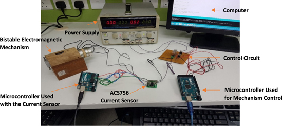
Figure 11. Experimental setup for the current consumption measurement of a bistable electromagnetic mechanism.
Download figure:
Standard image High-resolution imageFrom the experimental data, the energy consumption of the proposed design in the engaging and disengaging operations was investigated. Initially, the current and the voltage consumption of the design during operation and engagement was investigated. Figure 12(a) shows the current and voltage consumption of the bistable coupling mechanism. A current flow of 2 A through the circuit load can be observed for 12 ms (bistable coupling mechanism). After that, a current value of 0 A can be observed though the operation. Similarly, for the voltage, a positive value of 23.0 V was recorded within a time period of 12 ms. From the experimental results, it can be noted that the proposed design only consumes the current and voltage for a period of 12 ms. This occurs during the engaging process of the proposed mechanism. After engagement, it can be observed that the mechanism does not consume any current or voltage for continuous operation. The total energy and power consumed during the engaging process is 46 W and 0.552 J respectively. Figure 12(b) shows the power and energy consumption during the engaging of the coupling mechanism.
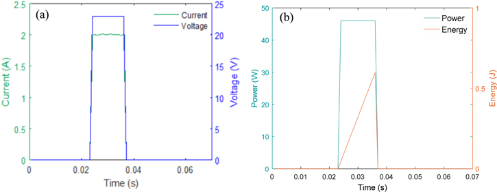
Figure 12. (a) The current and voltage consumption of the bistable electromagnetic mechanism during the engaging and mechanism operation. (b) The power and energy consumption of the bistable electromagnetic mechanism during the engaging and mechanism operation.
Download figure:
Standard image High-resolution imageFigure 13(a) shows the current and voltage consumption of the mechanism during the disengaging process. It can be observed that current is consumed only during the time of disengaging, which lasted 12 ms. The amount of current and voltage consumed during the 12 ms period was −2.0 A and −23.0 V respectively. Negative values were recorded for the current and voltage readings during the disengaging process. Negative readings were observed due to the reversing of the direction of current flow in the disengaging process. Figure 13(b) shows the power and energy consumption during the disengaging of the coupling mechanism. The amount of energy and power consumed during the disengaging operation was 0.552 J and 46 W respectively. In both the engaging and disengaging processes, the equivalent amount of energy and power are utilised.
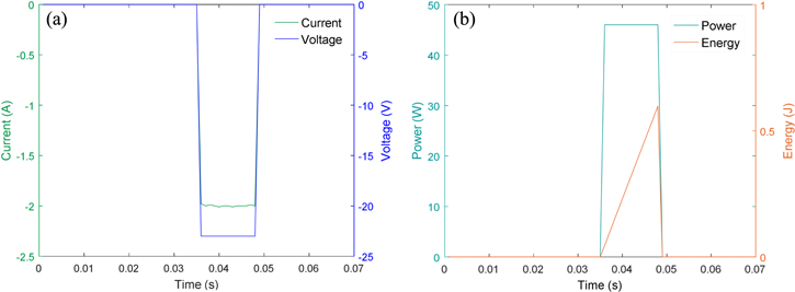
Figure 13. (a) The current and voltage consumption of the bistable electromagnetic mechanism during disengaging and mechanism operation. (b) The power and energy consumption of the bistable electromagnetic mechanism during disengaging and mechanism operation.
Download figure:
Standard image High-resolution imageThe proposed mechanism was implemented on a single link manipulator. The energy consumption of the design was monitored during the motion of the manipulator link. Figure 14 shows the experimental setup used for the analysis. The motion of the link was controlled by engaging and disengaging the proposed bistable coupling mechanism. During the experiment, the manipulator link performs a motion of 200 degrees from the time of engagement to the disengagement of the mechanism. The current consumption of the complete system was monitored throughout the entire motion of the link and it is shown in figure 15(a). The negative current values recorded during the disengaging of the mechanism are considered as positive when analysing the current consumption of the complete system in figure 15(a). Similarly, the current utilisation of a conventional electromagnetic clutch and the entire system were analysed, as shown in figure 15(b). The link trajectory of the manipulator and other experimental aspects were kept equivalent in both experiments.

Figure 14. The experimental setup used for the measurement of the current consumption of the single link manipulator during actuation with a bistable electromagnetic mechanism.
Download figure:
Standard image High-resolution image
Figure 15. (a) The total current consumption of the system, including the bistable coupling mechanism and independent current consumption of the motor during link motion. (b) The total current consumption of the system, including the electromagnetic clutch and independent current consumption of the motor during link motion.
Download figure:
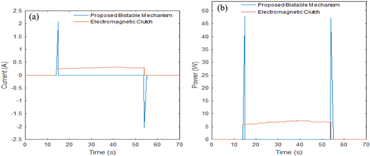
Standard image High-resolution imageIn figures 15(a) and (b), sections A1 and A2 show the consumption of current in the entire system prior to the engagement of the bistable electromagnetic coupling mechanism and the electromagnetic clutch respectively. Similarly, section E1 shows the current consumption of the system after disengagement of the mechanism. Section E2 shows the current consumption of the system after disengagement of the electromagnetic clutch. Section C1 and C2 in both figures 15(a) and (b) indicate the usage of current during the link motion. B and D in figure 15(a) show the current consumption of the manipulator system during the engaging and disengaging process of the bistable coupling mechanism respectively. Apart from the utilisation of current in the motor, the proposed mechanism and the electromagnetic clutch were also observed independently during motion. Figure 16(a) displays the independent usage of current by the bistable coupling mechanism and the electromagnetic clutch.
Figure 16. (a) The current consumption of the bistable coupling mechanism and the electromagnetic clutch during link motion. (b) The power consumption of the bistable coupling mechanism and electromagnetic clutch during link motion.
Download figure:
Standard image High-resolution image
It can be observed in figure 15(a) that the current utilisation of the entire system in sections A, C and D is equivalent to the motor current consumption. Furthermore, the combined current consumption of the coupling mechanism and the motor in figure 15(a) varies from the motor current utilisation graph only at points B and D. The variation is only observed at two instances, namely at the time of engaging and disengaging the mechanism. Therefore, it is apparent that the mechanism only utilises power (46 W) during the engaging and disengaging of the bistable coupling design. Furthermore, figure 16(a) also indicates that current is only consumed in two instances (engaging and disengaging) throughout the complete motion of the manipulator link. The total energy utilisation of the proposed design is computed using the area under the power graph, and it is about 1.104 J. The power consumption of both the electromagnetic clutch and the proposed bistable coupling design is presented in figure 16(b). In figures 15(b) and 16(a) it can be observed that current is supplied to the conventional electromagnetic clutch uninterrupted throughout the motion of the manipulator link. This is because a continuous supply of current is a vital requirement for an electromagnetic clutch to maintain its engaged state.
The energy consumption of the electromagnetic clutch is computed for the entire manipulator link motion and it is about 271.445 J. Therefore, it is apparent that in underactuated manipulators with electromagnetic clutches, the electromagnetic clutches utilise large amounts of additional energy during the manipulator motion apart from the motor. However, the consumption of energy in the proposed design is only observed in two states, namely the engaging and disengaging of the mechanism. The total energy consumed by the bistable coupling mechanism during the manipulator link motion is about 1.104 J. As such, it can be observed that the conventional electromagnetic clutch has additionally consumed 270.336 J of energy during the link motion with respect to the proposed mechanism. The total energy utilised by the proposed mechanism for the entire motion is only about 0.406% with respect to the energy consumed by the conventional electromagnetic clutch for the equivalent motion scenario. Therefore, it is apparent that the proposed design is effective in reducing the consumption of electrical energy in comparison with the conventional electromagnetic clutch. Furthermore, as a result of the continuous flow of current through the electromagnetic coil, heat energy is generated and dissipated from the coil, reducing the efficiency of the clutch. The experimental results obtained indicate that the electromagnetic coil of the proposed design is energised for a maximum of 12 ms. Thus, the time that the electromagnetic coil remains in an energised state has been reduced in comparison with the conventional electromagnetic clutch. As such, the proposed design is effective in reducing the dissipation of heat energy as well as enhancing the mechanism efficiency. The bistable mechanism employs permanent magnets to provide the holding force required. Therefore, to conserve the state of the mechanism no external power is utilised. Hence, the proposed design can sustain its present state in conditions of sudden power failure. Moreover, a current pulse needs to be supplied for the transition of state of the proposed bistable coupling design. Hence, the proposed design is not only energy efficient, but also provides a fail-safe mechanism.
6. Conclusion
In this paper, the design of an energy-efficient and safe bistable electromagnetic mechanism is presented, which can be implemented on underactuated lightweight manipulators. The experiment results obtained show the effectiveness of the proposed bistable electromagnetic mechanism. The current and voltage consumption results obtained highlight the significance of the proposed mechanism in reducing the electric energy usage in comparison with a conventional electromagnetic clutch. The fabricated prototype design was implemented on a single link manipulator to investigate the operation. To evaluate the performance of the design, theoretical and experimental analysis were performed. The theoretical model developed shows a good correlation with the experimental results. In addition, the proposed bistable electromagnetic design is safe to operate compared to traditional electromagnetic clutches due to the permanent magnetic bistable design. The design maintains the stable state of the mechanism even in the absence of electric power. Hence, the mechanism is unaffected by sudden power failure. Therefore, the proposed bistable electromagnetic mechanism is capable of providing an energy efficient and safe mechanism for underactuated lightweight manipulators.
Acknowledgments
The authors confirm and declare that there are no conflicts of interest associated with this publication.