
Abstract
Kinetic energy harvesting with piezoelectric bimorphs has attracted considerable research interest in recent years. Many works have been dedicated to the modelling and optimisation of the cantilevered geometry to increase power density, bandwidth, etc. The increased efficiency coming from the use of trapezoidal beams has been recognised, but little has been done to produce the same uniform strain within the most commonly available rectangular beams. This work proposes a new approach via a compliant rotational structure which permits to deform a set of bimorphs in pure bending. When applied to a harvester with multiple bimorphs, since their deflections are synchronous, the power signals produced are in phase and power conditioning is simplified and made more efficient. The kinematic requirements for uniform strain are discussed, the novel structure is proposed and modelled with finite elements, a prototype is presented and characterised to support the modelling. Modelling shows that the proposed structure induces almost perfectly uniform strain in the piezoelectric beams for all useful rotation angles, demonstrating that, compared to a traditional cantilever, twice as many charges can be produced when the same maximum strain is applied to the material. Experiments with a prototype having sectioned electrodes permitted to demonstrate that the tip, almost inactive in the traditional cantilever configuration, can be made to generate even more charges than the root. Experiments with a step in applied torque simulated plucking excitation and confirmed both synchronicity and the benefits of pure bending. Furthermore, excitation by base-vibration at 56.7 Hz and 5g acceleration produced 3.4 mW in the bimorph subjected to pure bending and 1.3 mW for the reference one. The principle of synchronous pure bending via helper structures can be applied in general to increase the performance of piezoelectric energy harvesters.
Export citation and abstract BibTeX RIS
1. Introduction
Manufacturers of microelectronic components have been increasing their effort to reduce power consumption of devices. Starting a decade ago, power requirements of microcontrollers have decreased to the point that it has become meaningful to seek to power small intelligent system by using stray energy present in the environment where they operate. Energy harvesting (EH) has therefore developed into an independent area of research with the aim of enabling the deployment of energy autonomous systems. Due to the variety of stray energy present in different environments, a wide range of energy harvesting techniques and materials are being researched: thermoelectric [1] and electrostatic generators [2], electromagnetic induction [3] and so forth.
Leveraging on the presence of movement in many environments, considerable effort is being devoted to kinetic energy harvesters, particularly using electromechanical transducers like piezoelectric devices.
There are many examples in the literature of works aimed at improving different aspects of kinetic energy harvesters. A range of low profile and small footprint devices are reviewed in [4]. Recently, the response bandwidth of vibrational harvesters has attracted considerable interest: since environmental vibrations may fall over a wide range of frequencies, harvesting effectiveness can be increased with wideband devices. An array of beams, each with its own natural frequency and together covering the desired bandwidth, has been used in several studies [5, 6]. Frequency tuning has been demonstrated by changing the stiffness of the cantilevered beam by exploiting magnetic interaction [7]. A wider operating band has also been achieved by introducing nonlinear response and chaotic behaviour [8, 9]. Another way of addressing bandwidth limitations is with the plucking excitation, suitable for applications with very low input frequency [10].
There are fewer works dedicated to improving the effective use of the piezoelectric material. The advantages of triangular or trapezoidal beams, and the uniform strain that can be achieved within them, have long been recognised for actuators [11] and for energy generation [12, 13]. Often researchers have extended the vibrating beam by adding inert materials, extensions and extended seismic masses [14, 15], with the intent of increasing the bending moment applied at the tip of the beam. The fabrication of more complex beams with varying thickness was also proposed to increase the strain uniformity and thence energy harvesting performance [16]. Air-spaced piezoelectric cantilevers have also been offered as an alternative to conventional bimorphs with the advantage of producing, if well designed, higher voltages and more uniform strain [17]. More recently, the principle of four-point bending has been applied to vibrational energy harvesting [18]. The common goal of the works just described is a greater uniformity of strain within the piezoelectric material.
The state of pure bending deformation is of interest in several other research areas and efforts are recorded to devise mechanisms that permit testing of materials in pure bending. In many cases, the mechanics is complex. In textile testing, the Kawabata evaluation system for fabrics is used. Relatively simple mechanisms have been devised to test materials of interest to cryogenics, although they only approximate the desired deformation [19, 20]. More complex systems for biomechanical testing of spine segments have been proposed [21, 22]. The testing systems for larger samples of generic shape are even more complex [23]. These few examples highlight the difficulty of producing pure bending, although high complexity is acceptable when mechanisms are designed for testing of materials. For an energy harvesting application, the structure must be much simpler to minimise costs, dimensions, weight and energy dissipation. The aim of this paper is to present a compliant structure for piezoelectric energy harvesting which achieves pure bending to maximise the utilisation of the material, while also ensuring the synchronicity of power signals produced by an array of bimorphs.
The majority of energy harvesters presented to date focuses on a single piezoelectric bimorph. However, in many applications there is an opportunity to place more transducers, which could work in concert to maximise the energy extracted from the environment. If they are active at the same time, the issue of synchronicity arises. Since the out-of-phase vibration of several transducers would yield a partial cancellation of the signal, with electrical energy produced by one re-injected into another, system efficiency is compromised. To avoid signal cancellation, individual rectification has been added to each bimorph before further power management or storage [5, 24]. This has several disadvantages, including cost and complexity of the electronics and losses in the numerous rectifying bridges. A better power management, based for example on synchronised switch harvesting on inductor or single supply pre-biasing [25], would be even more costly and it is impractical to have identical copies of such circuit for each of the many bimorphs an application might rely on. It is therefore necessary to devise a way to synchronise the outputs of the many piezoelectric devices in a harvester so that they work in unison and provide outputs without phase shifts between them. The proposed solution, for rotational harvesters, relies on a ring onto which the tips of the bimorphs are attached, so that when this rotates with respect to a central hub (holding the roots of the beams), the vibrations of the bimorphs are synchronised.
2. Geometry for pure bending
Since excessive tensile stress levels reduce the operating life of ceramic piezoelectric transducers by introducing cracks and, eventually, causing failure of the material, it is worthwhile to consider the stress/strain distribution within a piezoelectric beam used for EH. A geometry where there is a stress concentration in one small area implies that to protect it from premature failure, other regions will be subject to lower than optimal stress levels. This reduces performance as the electrical output will be determined by an averaged value of strain. Considering bimorphs or monomorphs, which work in 31 mode, the ideal situation is to have a uniform stress/strain field along the beam (direction 1); however, the traditional cantilever configuration has zero strain at the tip. Within a bending beam, the maximum strain will be observed at the external surfaces of the device, decreasing as we move inwards towards the neutral surface. The tensile strain ε at the convex external surface of a beam with rectangular cross section can be estimated as the product of half-thickness θ and curvature:

where ξ is the longitudinal coordinate and w(ξ) is the deflection of the beam from the relaxed horizontal position; all coordinates are adimensionalised. Note that for small deflections the omission of the denominator leads to an acceptable approximation.
Starting from standard equations found in textbooks for the shape of: a vibrating cantilever, a statically deflected cantilever and a beam bent into an arc, respectively, it is easy to show that the expressions (2)–(4) are valid. These were normalised so that the same value of strain is present at the root, ε(0) = ε0:
- 1.first mode vibration of a uniform cantilevered beam (k1 ∼ 1.875):

- 2.static deflection of a cantilever due to a point load at the tip, also approximating the dynamic deflection in the presence of a large point mass at the tip:
- 3.pure bending deflection of a uniform beam (boundary loads are such as to deform the beam into an arc):


The corresponding shapes are plotted in figure 1 for θ = 0.0125 and ε0 = 0.001, together with the tensile strain along the beam calculated, in each case, with expression (1). Note that in piezoelectric beams the tensile strain should be kept below 0.001 at all times to reduce the probability of early failure [26].

Figure 1. Deflection of a beam in a selection of bending configurations and corresponding strains at the external convex surface.
Download figure:
Standard image High-resolution imageObservation of the figure reveals that whereas the strain in the arc is uniform, for a static deflection it decreases linearly from the maximum at the root to zero at the tip; for first mode of vibration, the strain decreases even faster. In other words, for shapes different from an arc the average strain is half (or less) of what it could be; the charges extracted from the material are correspondingly lower. Yet another point of view is to state that a design that uses the piezoelectric material more effectively by implementing pure bending may be able to provide the same harvested energy by using a third of the amount of material, which could mean reduced cost, mass and volume.
Having established that deforming the beam into an arc is the most material-efficient route to piezoelectric energy harvesting, the objective is to devise an arrangement to produce the required end-loads. Figure 2 illustrates the relevant geometry, representing the beam bent while keeping the end at N fixed (equivalently, we could think of M and N being rotated by equal and opposite angles). With reference to the figure for the meaning of the symbols, some key relations, derived from elementary geometry, are:
where ε is the maximum tensile strain present, found at the external surface of the beam. The most important observations are that the distance r between the tip (M) and the root (N) changes with deflection, implying that a simple rigid lever pivoted in N cannot be used to guide M along the correct path. Also, the tangent to the beam in M' intersects MN in a point Q' which moves along the beam with α, so neither that point is a good candidate as a pivot. Two key geometrical conditions must be satisfied: the ends rotate, assuming an angle α/2 from the line connecting them, and the distance between the ends reduces, according to expressions (5). The aim is to design a structure capable of satisfying, with good approximation, both requirements.
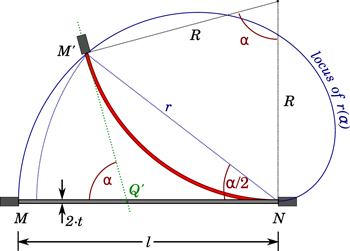
Figure 2. Geometry of the beam bent into an arc.
Download figure:
Standard image High-resolution image3. Pure bending in a rotational device
In a rotational harvester like the Windmill [27] or the Pizzicato [10], piezoelectric bimorphs are cantilevered and placed radially, like spokes on a wheel; the relative rotation of external ring and central hub makes them vibrate or deflect. Neither device above attained both synchronicity and pure bending. The general problem stated in the introduction is here tackled for applications where the input energy takes the form of relative rotation. As discussed in the previous section, the structure must impose the same and opposite rotation on the two ends of the beam and accommodate the reducing distance between them. The structure must also permit the synchronous excitation of an array of bimorphs. An arrangement with the potential of producing the required rotations is illustrated in figure 3. The bimorph is held between a rotating hub and an anchor which is hinged in P to an external ring, held fixed. A rigid rod connects a point A on the anchor to a point B on the hub, so that when the latter rotates, it forces a rotation of the anchor around P. Since this is only a sector of a circle, several bimorphs can be similarly mounted and simultaneously excited. With reference to the figure for the labelling of the points, before rotation of the hub the following equality is satisfied:
and after the hub has rotated by an angle ϕ:

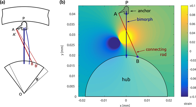
Figure 3. (a) Conceptual sketch of structure for rotational pure bending: thinner lines after rotation; (b) colourmap of strain in the connecting rod according to location of end A.
Download figure:
Standard image High-resolution imageThe rotational requirement means: as the hub rotates clockwise (CW) by ϕ, the anchor holding the tip of the bimorph rotates counter-clockwise (CCW) by ϕ. This translates into the following transformations:
If the lengths of vectors  and
and  are equal, then a rigid rod connecting points A and B will couple the two rotations to satisfy the requirement—when the hub rotates, the anchor will be forced to rotate by the same angle in the opposite direction.
To explore the locus of the points where the above requirement is satisfied, a simple MATLAB script was developed which explores possible locations for point A once both the required total rotation ϕ and the location of B are set. In principle, B could be anywhere, provided that it is fixed to the hub; it was selected as lying on its circumference to avoid complex manufacturing. It was observed that the locus changed with ϕ, particularly at large angles. Figure 3(b) illustrates a typical result, obtained with dimensions specific for the prototype developed later and for a rotation of 40 mrad (estimated to induce a uniform strain just over 0.1%).
In figure 3(b), there are two nearly circular regions where the strain rises steeply in absolute value to exceed 10%. Care should be exercised to keep A far from these because of the extreme dependence of strain on exact location. Points in the upper-right region experience an elongation of the rod connecting A to B (positive strain), whereas a contraction is observed in the lower-left region (negative strain). For practical reasons, it is better to have A close to the anchor (as in figure 3). In keeping with the current aim, the region near the anchor is within a uniform shade of colour just above 0% strain. These results apply to a situation which is in many ways ideal and not realisable in practice; nonetheless, they suggest that it is possible to find a location for point A such that the desired rotations of the beam's ends will leave  almost unchanged. When the direction of rotation is reversed, the same rod will be in compression (although there is no perfect symmetry). The resulting stress (positive or negative) means that the rod will develop the required forces. A final design should be symmetric, with criss-crossing rods.
As mentioned, the locus of points satisfying the condition  changes with the angle of rotation; this is detrimental as it means that, as the beam deforms, it goes through stages when the strain is not uniform. However, it is observed that variations are not significant as long as rotations are limited to several degrees. This will be further addressed in the next section.
Results as in figure 3 provide a starting point, but more accurate design needs to be performed with the aid of finite element analysis (FEA). Corrections are needed to account for the compliance of the connecting rods, for example. Furthermore, more compliance needs to be built into the anchor, as necessary to accommodate the change in distance between the two ends of the beam during bending. Geometrical analyses also assume that all pivots are ideal, whereas the FE model is able to describe the behaviour of the compliant hinges that replace them in a real structure.
4. FE modelling of rotational device
The structure designed to apply synchronous pure bending to a set of piezoelectric bimorphs is illustrated in figure 4 (only one 45° sector of a full 8-element array is shown and modelled). The model was developed in Comsol Multiphysics 4.2. As can be seen in figure 4(a), the free triangular mesh used has been significantly refined in the areas subject to stress concentration (maximum element size 0.4 mm); further refinement of the overall mesh did not lead to significant variations in the predicted strain. The material making the structure was assumed to be PMMA with a Young's modulus of 2.8 GPa and Poisson's ratio of 0.4. For the piezoelectric layers, the material PZT-5J from Comsol's standard library was selected as most representative. The perimeter of the 45° slice of hub was fully constrained, excluding the fillets of the connecting rods; rotation was imposed by a rotation of this boundary, which is indicated by a blue line in figure 4(a). The top line of the external ring (in green in the same figure) was constrained to zero displacement. Finally, regarding the electrical boundary conditions, the bimorph was in short circuit, so that the charges moving between electrodes could be calculated. The actual design is a 3D layered structure, later discussed in detail with the aid of figure 7, where the bimorphs are sandwiched between two layers which provide the connecting rods. The structure shown in figure 4 was designed for manufacture from sheet material. The plane strain approximation was used in the 2D FE model, because components that experience important strain are significantly thick. The simple pivot between anchor and outside ring (point P in figure 3(a)), has been replaced by a compliant elliptical hinge, which permits rotation but also a certain degree of extension towards the hub. Since the model is 2D, the rods are modelled only in part and where they would cross and overlap the piezoelectric beam, they are separately joined by connectors (mathematical constraints that behave like stiff connecting beams, by transferring forces and moments). Since focus was on observing the strain in the bimorph during bending, a static solution was sought (Stationary Study).

Figure 4. (a) Mesh of the FE model, indicating the constraint at the top (green) and the rotation imposed to the blues lines in the hub; (b) von Mises stress within the supporting structure when α = 25 mrad. For a measure of vertical scale, the whole bimorph is 25 mm long.
Download figure:
Standard image High-resolution imageAlthough the reliability of the structure was not optimised, figure 4(b) shows that the von Mises stress in it suggests a minimal risk of failure with less than 30 MPa observed everywhere but around a few FE nodes. Figure 5 shows the longitudinal strain (along the vertical axis) in the bimorph as deformed by a rotation of 25 mrad while subject to one of three boundary conditions. In figure 5(a), the proposed structure is modelled, with connecting rods imposing a suitable rotation of the anchor. The colouration reveals that the strain is uniform along the beam and symmetric with respect to the neutral surface, as desired. In figure 5(b), the structure was modified by removing the rods, whereas the anchor at the tip is preserved and is connected via the same elliptical hinge to the constrained ring. Finally, in figure 5(c), the simple cantilever configuration is modelled, where the anchor is removed and the nodes at the top edge of the beam are constrained to zero displacement in the x-direction only. The extremes of the colourbar are observed only in the areas next to the clamps and are unlikely to appear in a real device where corners are less sharp.
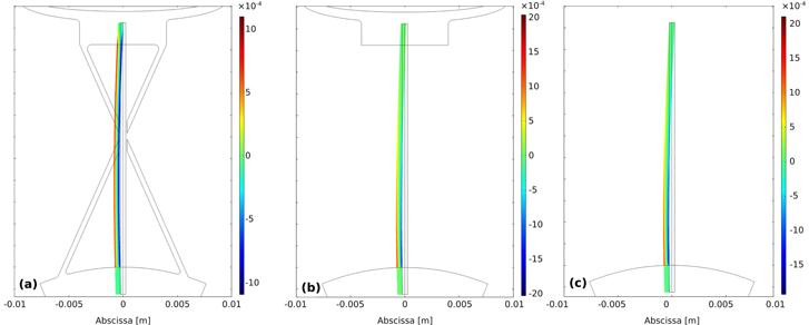
Figure 5. Longitudinal strain (along the vertical axis) in the deformed beam, superimposed to the undeformed structure, when α = 25 mrad (a) with connecting rods (b) without connecting rods (c) simple cantilever arrangement. For a measure of vertical scale, the whole bimorph is 25 mm long.
Download figure:
Standard image High-resolution imageFigure 6 illustrates the shape of the bimorph under rotations between 12.5 and 100 mrad in the same three arrangements represented in figure 5. The figure also reproduces the longitudinal strain along the external surface of the bimorph (in tension). These FEA results should be compared with figure 1, keeping in mind that the former have the same rotation whereas the latter were obtained for a normalised strain at the root. It is possible to appreciate that the full structure produces a good approximation of an arc, with strains that are almost constant within the un-clamped region. The results from the simple cantilever agree with the classical predictions: linearly decreasing from a maximum at the root to zero at the free end. In comparison with the latter, the anchor without connectors has a moderately negative impact on the strain, which may become negative in the last couple of millimetres for the largest angle. In fact, careful observation of the deflection plots reveals that there is a change in concavity near the un-connected anchor. It is important to note that although the average strain is similar for all conditions, the maximum strain produced by the full structure is approximately half of that of the other arrangements.
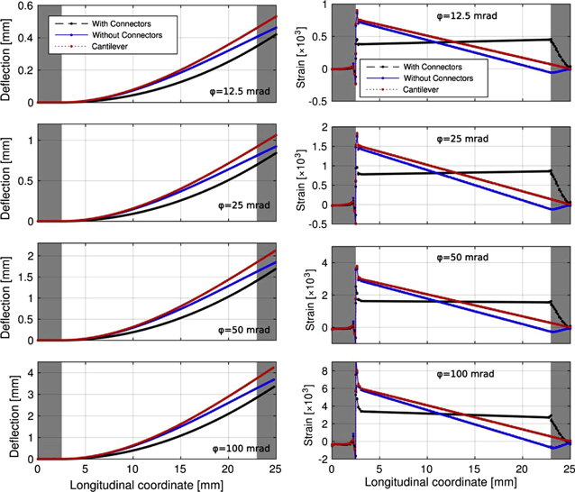
Figure 6. FEA results for the three boundary conditions in figure 5 (as in legends) and for four angles of rotation (as indicated in each graph). Deflection and strain (as indicated in ordinate) along the beam. The whole length [0, 25] mm is represented, with grey areas indicating the regions held in either hub (left) or anchor (right); for the cantilever, only the left region is held.
Download figure:
Standard image High-resolution imageIn summary, the results reported in this section demonstrate that it is possible to design a compliant structure than imparts pure bending deformation onto piezoelectric beams. A circular sector like this could be repeated several times (eight in the FE model above) and since the outer ring will be rigid, all beams will also be deformed in synchronicity.
As a design guideline, it was observed that the stiffness of the connecting rods is key to a uniform strain: if the rods are too compliant, the anchor does not rotate sufficiently and lower strains are seen at that end; vice versa if lower strains are observed near the hub, the rods should be less stiff or point B (figure 3) should be closer to the bimorph.
The extreme situation is when the rods are completely removed. As seen in figure 6, the strain progressively decreases moving from the hub to the external ring, confirming that the deflection is similar to that of a cantilever with tip load. This design retains the advantage of synchronicity, but with approximately a third of energy harvesting capability (for comparable maximum strain). The connecting rods are an essential feature of the structure proposed.
Table 1 collects the surface strain calculated by FEA in three regions (near the hub, near the anchor and half way) and the corresponding total charges for a selection of conditions. Data confirm earlier statements that to generate the same amount of charge, the maximum strain in pure bending needs only be about half that at the root of a cantilever. The last column in the table, giving the ratio of charges over angle, is of interest for applications where the input angle is limited. Comparing the values with and without connectors, it is noticed that for the same rotation angle approximately 30% more charges are generated with connectors than without.
Table 1. Summary of total charge available and maximum strain at the outer surface in three positions along the beam bent into an arc (connecting rods: yes) and approximating a cantilever with tip loading (connecting rods: no), for a set of four rotation angles. The entries have been sorted by ascending charges, in view of energy harvesting applications.
| Connecting rods | Angle (mrad) | Charge (μC) ↑ | Tensile strain near hub (/10−4) | Tensile strain at middle (/10−4) | Tensile strain near anchor (/10−4) | Charge/angle ratio (μC rad−1) |
|---|---|---|---|---|---|---|
| No | 8.0 | 0.72 | 4.54 | 2.26 | −0.02 | 90 |
| No | 16.0 | 1.44 | 9.09 | 4.52 | −0.04 | 90 |
| Yes | 12.5 | 1.46 | 3.89 | 4.22 | 4.55 | 117 |
| No | 32.0 | 2.88 | 18.2 | 9.04 | −0.13 | 90 |
| Yes | 25.0 | 2.90 | 7.97 | 8.34 | 8.71 | 116 |
| Yes | 50.0 | 5.69 | 16.6 | 16.26 | 15.9 | 114 |
| No | 64.0 | 5.71 | 36.6 | 18.00 | −0.67 | 89 |
| Yes | 100 | 10.99 | 34.4 | 31.34 | 28.2 | 110 |
5. Prototype
A prototype was manufactured to verify the feasibility and the advantages of the ideas expressed thus far. As illustrated in figure 7, it is composed of three layers: the external ones are laser cut from a 3 mm thick PMMA sheet and provide the connecting rods, whereas the middle layer holds the piezoelectric bimorphs. The structure is designed to accommodate up to 8 bimorphs and four were actually installed. Two of these bimorphs, found at diametrically opposite locations around the centre, were used for all experiments and are referred to in the following as PZT#2 and PZT#4. The bimorphs are parallel devices (Steminc, SMBA25W7T05PV) with an internal metal substrate of thickness 0.25 mm sandwiched between two piezo-active layers of thickness 0.125 mm. The material is a soft PZT branded SM411 (nominally equivalent to PZT-5J). The bimorphs are 7.1 mm wide and 25 mm long; approximately 2.5 mm of this length are embedded at either end for support, leaving 20 mm of active length. The two external electrodes were shorted together to form a two-terminal device with the substrate electrode. PMMA was selected for anchors and connecting rods for its strain capabilities and ease of manufacture via laser cutting.
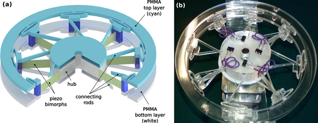
Figure 7. (a) ¾ view of the harvester (b) photograph of the prototype.
Download figure:
Standard image High-resolution image6. Experimental results
The first experiment measures the dependence of the charges produced by a bimorph on the angle of rotation. A torsional bar was fixed to the hub and rotated between the limits of a series of four stoppers, designed to give controlled and reproducible maximum rotations. The angle of rotation in each direction was calculated from the linear displacement of the edge of the bar measured with a dial test indicator, yielding an estimated uncertainty below 0.5 mrad. The charges flowing from one electrode to the other during each rotation were measured with an electrometer (Keithley 6517B); they are reproduced for one of the bimorphs in figure 8(a). Figure 9 summarises the results for a selection of angles.
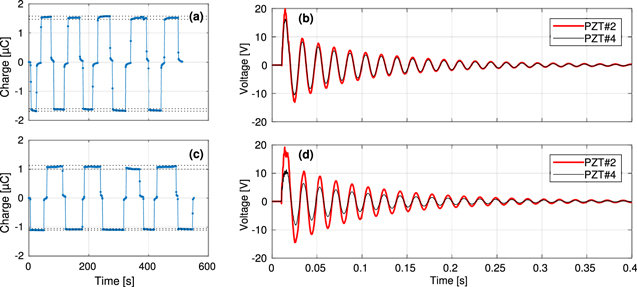
Figure 8. (a), (c) Charge versus time in quasi-static tests on PZT#4. The hub was rotated alternatively CW and CCW, covering a total of 30.5 mrad, with brief pauses in the relaxed position; (b), (d) voltage versus time when prototype is subject to impact excitation; (a), (b) with connecting rods present; (c), (d) with connecting rods removed.
Download figure:
Standard image High-resolution image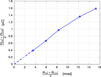
Figure 9. Charges versus rotation angle for slow controlled rotation. As indicated, the CW and CCW measurements are combined to remove the effect of offsets in the middle position.
Download figure:
Standard image High-resolution imageThe torsion bar was then struck to produce impact excitation. Each bimorph was connected to a separate channel of the DAQ (NI 9221), so that the only impedance between its terminals was the input impedance of the DAQ (nominally 1 MΩ//5 pF). In all cases the two active bimorphs responded with similar amplitude and with the same frequency and phase. In figure 8(b) one such event is plotted, which demonstrates that synchronicity is achieved.
After full characterisation of the device in its original configuration, as discussed until this point, the connecting rods were removed from the section holding PZT#4. The objective was to measure directly the gain produced by their presence. Data plotted in figure 8 were collected just before and just after such operation, to ensure experimental conditions were not altered. It is worth observing that the other 14 rods were not removed, so the symmetry of the structure was minimally modified.
As a final step, narrow strips (<1 mm) of the electrodes on each side of both PZT#2 and PZT#4 were removed so as to divide each electrode into two approximately equal sections, one near the root and one near the tip. After this procedure, each bimorph had 4 side electrodes plus the substrate. By connecting together each pair of opposed electrodes (i.e. the pair at the root and the pair at the tip) and measuring the charges between each pair and the substrate, two sub-transducers are formed (see figure 10(a)). The charges generated in each sub-transducer are therefore a measure of the strain in the corresponding region. Charges were collected under a 30.5 mrad rotation CW and an equal rotation CCW. The rotations were conducted as square waves with a period of approximately 30 s. Table 2 reports the data collected in this experiment.
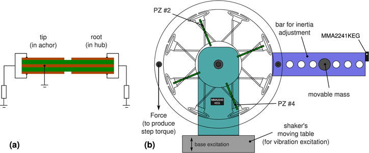
Figure 10. (a) Electrical circuit used for measurements of energy and power generated, indicating the regions in which the bimorph has been subdivided and the wiring of the resistive loads; (b) schematic of the mechanical configuration for the application of a step in torque and for the base-vibration tests.
Download figure:
Standard image High-resolution imageTable 2. Charges produced near the root and near the tip of the bimorphs under slow rotation. The uncertainties reported correspond to 2σ.
| Device | Connecting rods | Rotation | Charges (μC) at root | Charges (μC) at tip |
|---|---|---|---|---|
| PZ#2 | Yes | CW | 1.61 ± 0.03 | 2.46 ± 0.05 |
| PZ#4 | No | CW | 1.91 ± 0.03 | 0.32 ± 0.02 |
| PZ#2 | Yes | CCW | 1.63 ± 0.03 | 2.42 ± 0.06 |
| PZ#4 | No | CCW | 2.02 ± 0.07 | 0.29 ± 0.02 |
The plucking excitation of piezoelectric bimorphs has gained considerable momentum since its introduction [10]. To test the suitability of the proposed structure to this mode of operation, the prototype was subjected to steps in the torque applied to the outer ring while the hub was clamped:
where H() is the Heaviside step function, T0 = 0.24 Nm in all tests and t0 an arbitrary time at which the step occurred. As shown in figure 10(b), a bar was rigidly attached to the outer ring, so that a selection of moments of inertia could be produced, simply by fixing additional mass (mi) at different distances from the centre of the hub (ri). This allowed the determination of the constant of rotational elasticity (K) and the moment of inertia of the structure (I0) by measuring the natural frequency of vibration (ω) following the step. In a linear approximation:

Once the natural frequencies, ω1 and ω2, are measured for two configurations (i = 1, 2) of mass and distance, it is easy to show that:
The structure was also instrumented with two Freescale MEMS accelerometers (MMA2240KEG to monitor the base and MMA2241KEG at the end of the bar, as shown in figure 10(b)).
Observing figure 7, it is clear that when collecting energy from an individual bimorph a large proportion of the structure does not take part in the generation; it is therefore to be expected that in such condition the harvester is weakly coupled. This was demonstrated by observing the frequency response to a step in open and close circuits: in figure 11 the frequency-shift due to the coupling is so small that it is not possible to determine it with any statistical meaning.
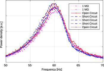
Figure 11. Fourier transform of the vibration response (acceleration) of the configuration with inertia of 1.7 × 10⁻⁴ kg m2 to a torque-step at a selection of electrical BCs (including the extremes of open and short circuit).
Download figure:
Standard image High-resolution imageFigure 12 reproduces sample results obtained when m = 7.32 g and r = 121 mm. The four traces correspond to the two regions (at tip and at root) present on each bimorph tested. A resistive load of 76 kΩ (resulting from a resistor of 82 kΩ in parallel with the 1 MΩ input resistance of the DAQ) was connected across each electrode and ground, as schematically represented in figure 10(a). The resistor value was calculated as 1/ωC, which is a valid approximation of the equation [28]:
in the weak coupling present (k ≪ 1) and the moderate damping observed (from a measure of FWHM of the open circuit spectral peak, ζ ∼ 0.05). A more accurate calculation of Ropt is needless, also taking into account that a wide range of frequencies is of interest (48–60 Hz), which would suggest a ±12% uncertainty in the calculation of the optimal resistor. The power spectral density in figure 12 permits the determination of the natural frequency, in this case 47.5 Hz. Table 3 summarises these results, reporting the energies generated in each of the four sub-transducers and the frequencies. A key result is the last but one column, showing that the bimorph with connecting rods generates 2.5 times the energy of the one without.
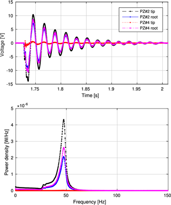
Figure 12. Response to a torque-step of the configuration with inertia of 2.8 × 10⁻⁴ kg m2; each channel, corresponding to a region, is connected to a 76 kΩ resistive load, as shown in figure 10.
Download figure:
Standard image High-resolution imageTable 3. Energy generated after a step in applied torque for a selection of overall rotational inertia. The damped frequencies are also tabulated. Each reported result is the average of at least three tests. These data permit the calculation of the moment of inertia (1.7 × 10⁻⁴ kg m2) and the rotational elasticity (25 Nm rad−1) of the structure.
| Inertia (kg m2) | PZ#2 tip (μJ) | PZ#2 root (μJ) | PZ#4 tip (μJ) | PZ#4 root (μJ) | Total PZ#2 (μJ)a | Total PZ#4 (μJ)a | Ratio of totalsa | Frequency (Hz) |
|---|---|---|---|---|---|---|---|---|
| 0.000 17 | 40 | 19 | 0.20 | 23 | 59 | 23 | 2.50 | 60.3 |
| 0.000 20 | 39 | 19 | 0.20 | 23 | 57 | 23 | 2.52 | 56.7 |
| 0.000 23 | 43 | 20 | 0.20 | 25 | 63 | 25 | 2.50 | 52.1 |
| 0.000 28 | 44 | 21 | 0.19 | 26 | 64 | 26 | 2.47 | 47.5 |
Data in table 3 show that the operating frequencies of the structure with tuned inertia are usefully low (in the 50–60 Hz range of mains supply). The structure was then tested in a more traditional configuration as a vibrational energy harvester. Assuming small rotations and linearity, the equation of motion of a structure, of viscous damping c and rotational elasticity K, subject to base excitation  is:
is:

where IO is the inertia of the balanced system, m is a point mass fixed at distance r from the centre O (assuming r is normal to  ). From the equation, it is seen that the forcing depends not only on the acceleration of the base and the mass, but also on the distance of the mass from the centre of rotation. This is advantageous with respect to translational systems as there is an additional parameter to adjust or tune the resonance of the harvester.
The structure was mounted on an electrodynamic shaker (Data Physics GW-V20 with PA100E power amplifier), with the hub rigidly connected to the shaker's moving table, as shown in figure 10(b). It was then subjected to sinusoidal vibrations of frequency matching the damped frequencies detected with the step experiments. The amplitudes, controlled by the signal into the amplifier, were measured by the base accelerometer. The same resistive loads discussed previously were used to measure the generated power, in each of the same four regions. Figure 13 reproduces typical results of these experiments for a 5g excitation amplitude at 56.7 Hz, for the configuration with inertia of 2.0 × 10⁻⁴ kg m2. Average power generated in each region and in each bimorph for an excitation of 1.0g are tabulated in table 4, for a range of configurations with inertia from 1.7 × 10⁻⁴ to 2.8 × 10⁻⁴ kg m2. The table also reports the amplitude of angular vibration (θ0), calculated from the acceleration a measured by the accelerometer located at the tip of the bar (at a distance r = 128 mm from the centre of rotation), using:

which is valid for the small rotations observed.

Figure 13. Plotted versus time, the voltage generated in the different regions of the bimorphs, as indicated in legend, and simultaneous acceleration of the base (data for inertia of 2.0 × 10⁻⁴ kg m2 and frequency of 56.7 Hz).
Download figure:
Standard image High-resolution imageTable 4. Average power generated by the four regions of interest with sinusoidal base excitation of amplitude 1.0g at the frequencies identified in the step experiments.
| Inertia (kg m2) | Frequency (Hz) | Angle of vibration (mrad) | PZ#2 tip (mW) | PZ#2 root (mW) | PZ#4 tip (mW) | PZ#4 root (mW) | Total PZ#2 (mW)a | Total PZ#4 (mW)a | Ratio of totalsa |
|---|---|---|---|---|---|---|---|---|---|
| 0.000 17 | 60.3 | 3.4 | 0.11 | 0.054 | 0.000 26 | 0.059 | 0.17 | 0.060 | 2.77 |
| 0.000 20 | 56.7 | 4.4 | 0.19 | 0.093 | 0.000 39 | 0.10 | 0.28 | 0.10 | 2.77 |
| 0.000 23 | 52.1 | 5.1 | 0.24 | 0.11 | 0.000 45 | 0.13 | 0.35 | 0.13 | 2.76 |
| 0.000 28 | 47.5 | 5.2 | 0.23 | 0.11 | 0.000 43 | 0.13 | 0.35 | 0.13 | 2.73 |
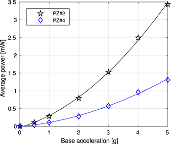
Finally, figure 14 shows the dependence of the average power generated by each bimorph on the excitation level at a fixed frequency (56.7 Hz in figure): data points are plotted together with fitted second degree polynomials (the origin was included in the data for fitting) for an inertia of 2.0 × 10⁻⁴ kg m2. Here, the ratio of the power generated by the two bimorphs is 2.7.
Figure 14. Effect of the amplitude of acceleration of the base on the average power generated by the two bimorphs (data for inertia of 2.0 × 10⁻⁴ kg m2 and frequency of 56.7 Hz).
Download figure:
Standard image High-resolution image
7. Analysis and discussion
Figures 8(a) and (c) highlight the variation of charge flowing through the external circuit of PZT#4 when the torsional bar is alternatively moved between the extremes of travel defined by the stopper. In both cases, the overall rotation of the torsional bar covers 30.5 mrad. Statistical analysis of these data yields a total charge difference of 3.2 ± 0.1 μC with rods and 2.2 ± 0.1 μC once rods were removed, implying a loss of 31% or, alternatively, that the connectors boosted performance by 45%.
Figures 8(b) and (d) reproduce the voltage signal under impact excitation (as mentioned above, PZT#2 was preserved intact for direct comparison). Whereas synchronicity is preserved, as expected, it is clear that the signal from PZT#4 is significantly reduced by the removal of the connectors. As the interest is in energy harvesting, it is useful to look at the ratio of energies produced by the two devices:
For the impact events in the figure, such ratio is 0.73 with connectors and 0.33 after their removal. This means that the PZT#4 has lost about 55% of its energy generation capability.
The results reported in table 2 unambiguously show that the structure is effective in imparting a large degree of strain at the tip of the bimorphs. Charges collected from the electrodes near the tip of the device without connecting rods (PZT#4) are only about 15% of those near the root. On the contrary, for the device with connecting rods (PZT#2) the charges near the tip are actually around 50% larger than those near the root. This has two reasons. Firstly, the rods manufactured may be stiffer than optimal, which would impose a larger strain at the tip, as previously discussed in section 4. Secondly, the electrode area near the tip is larger than the one near the root. This is indicated by measurements of capacitance, which is 32 nF near the root and 37 nF near the tip—a similar difference was observed on PZ#4, with the two capacitances being 35 nF (root) and 42 nF (tip). Data in table 2 also show that the structure has the required symmetry for positive and negative angles, as the difference between CW and CCW charges are in the order of the experimental uncertainties.
Data in figure 12 and in table 3 show the benefit of the connecting rods during Energy Harvesting by plucking: whereas the tip of PZ#4 (without rods) sources a very small signal and contributes very little power, the same region of PZ#2 (with rods) is the major contributor. Overall, the table indicates that PZ#2 generates 2.5 times the energy of PZ#4.
Synchronicity and the advantages of pure bending are also evident in figure 13: the voltage across the resistive loads show that the signal generated by the tip of the bimorph without connecting rods (PZ #4) is much lower than all others. This implies that whereas the two bimorphs experience a similar value of strain at their root (near the hub), only the bimorph with preserved connecting rods has high values of strain also at its tip. This is again confirmed by data in table 4, which also show some interesting trends. The angle of vibration increases with increasing inertia (obtained by increasing r, which augments the forcing in equation (6)), but the growth is limited by the fact that r is also at the denominator of equation (7). At the same time, the frequency of excitation decreases. As a result, the power increases fast at the beginning but slightly decreases at the highest inertia values explored.
Figure 14 shows that power outputs of over 3.4 mW can be produced by a single bimorph (with connectors) under an acceleration of 5g at 56.7 Hz. This means that a fully fitted harvester like the one proposed would generate 27 mW of power. On the other hand, if connectors were removed the power generated would be only 10 mW. Considering the similarity in predicted average strain between a bimorph without rods and a cantilevered one (figure 6), an array of an equal number of the latter would generate about one third of the power afforded by the proposed structure.
8. Conclusions
This paper has highlighted the importance of straining synchronously and uniformly piezoelectric bimorphs in an energy harvester to increase performance and durability. It has recalled several previous solutions, and brought out some of their limitations. The contribution of this paper is a novel approach to piezoelectric energy harvesting, where a compliant structure constrains a set of bimorphs to bend synchronously into arcs. In this way, both suboptimal utilisation of piezoelectric material and signal cancellation due to out-of-phase generation, common in previous harvesters, are successfully eliminated.
The proposed harvester has been geometrically analysed, modelled with FE and prototyped. The FE model indicates that for a set maximum strain, and hence design life, we can obtain over twice as many charges with this structure, and the approximate pure bending deformation it affords. The prototype demonstrated synchronicity of the generated power signals and that the design greatly boosts the charges produced by the region at the tip. Experiments simulating plucking excitation showed that almost three times the energy can be generated thanks to the approximation of pure bending achieved. Traditional base-vibration testing provided almost identical results, confirming the potential of the proposed structure for energy harvesting also in this common application.
This structure accepts reciprocating rotations of a few degrees as mechanical input. These may be originally oscillatory rotations or they could be obtained by transforming linear vibrations into rotational ones, as demonstrated in this paper. As such, one application of the proposed harvester is as a traditional vibrational energy harvester. Alternatively, energy can be input into the structure via impact or via plucking. Previous works have shown how relative rotation, for example in human joints [10], can be used to transfer mechanical energy into a harvester by plucking. This principle can be applied to the proposed structure by adding plectra on the ring, engaging with rotating teeth on a further external ring.
As energy harvesters move towards applications, their reliability over time must receive more attention. The structure presented offers the best use of the material available, within its operating limits.
Acknowledgments
The author would like to thank Dr W Sricharussin for valuable suggestions in the preparation of the manuscript and the reviewers for comments and observations which have permitted the delivery of a richer and clearer paper.