

Abstract
This letter investigates the energy harvesting capabilities of a novel hybrid wind and solar transduction device. The proposed device is an inverted-U shaped structure with a pair of piezoelectric benders connected by a flexible, tensioned photovoltaic ribbon. The tensioned photovoltaic ribbon member undergoes aeroelastic flutter limit cycle oscillations (LCOs) at low wind speeds, leading to time-varying tension forces applied to the piezoelectric benders, producing cyclic deflections and output voltage. Experimental characterization of the proof of concept energy harvester indicates that it is possible to obtain several milliwatts (mW) of power using the centimeter scale device, with an output power of ∼12.1 mW at a combination of 12 m s−1 wind speed and 100 W m−2 of solar irradiance, for indirect solar applications. It is shown here that an optimal combination of applied tensile preload and preset angle of attack exists which produces the highest wind power output of the system. An explanation of this behavior is also provided through the analysis of data collected on the photovoltaic ribbon velocity, piezoelectric voltage signals, and high-speed imagery, providing further insight to the motion kinematics of the highly nonlinear system response. Interestingly, the solar power output has been observed to remain invariant with increasing vibration velocity. This suggests that the gain in solar power efficiency from vibration-induced convective cooling negates any losses from the deflected incidence angle of the photovoltaic ribbon. These results illustrate that there is a negligible performance penalty in adding wind energy harvesting capability to the solar cells with this device concept.
Export citation and abstract BibTeX RIS
Introduction
Energy harvesting from environmental sources with small-scale devices has been a popular topic of research over the last decade due to the rapid proliferation of wireless electronics [1, 2]. Most of the devices developed during this time period focused on harvesting energy from a single source such as ambient mechanical vibrations. However, recently there has been increased interest in multi-source hybrid energy harvesting [3]. The hybrid energy harvesting concept is attractive because it enables a system to scavenge energy from disparate sources, without being solely dependent on a single source. For example, adding wind energy harvesting capability to a photovoltaic panel is appealing not only to provide a secondary energy source at night, but also in locations like urban canyons, under bridges, or beneath tree cover where direct sunlight is limited or unavailable, or in high latitude regions where sunlight is seasonally limited.
Exploiting aeroelastic vibration phenomenon to harvest energy from ambient airflow has been the subject of considerable interest recently [4–9]. It has been shown that aeroelastically excited oscillators can have competitive efficiencies and power densities with similarly sized traditional electromagnetic turbines at low operating wind speeds [10], and can offer the additional benefits of simple, solid-state construction. While most piezoelectric energy harvesters, whether aeroelastically excited or driven by base excitation, have used cantilevered designs [11], the proposed device uses an inverted-U geometry with clamped–clamped boundary conditions and a preload tension. Clamped–clamped designs have been shown to be advantageous in situations where the working environment may introduce unexpected strong excitations, which could break the piezoelectric transducers in a cantilevered configuration [12]. Furthermore, the clamped–clamped structure behaves nonlinearly to even small excitation levels thus limiting its deformation as well as extending its bandwidth of operation [13]. Aeroelastically excited clamped–clamped vibrating ribbons have seen some early commercialization attempts such as the Humdinger Windbelt which can produce mW's of power using aeroelastic flutter vibrations and electromagnetic transduction. Notably, predictive models for the combined nonlinear aerodynamics and nonlinear structural dynamics of such tensioned devices remain elusive in the literature. Compared to aeroleastic energy harvesting, solar energy harvesting is a more established domain, and the recent availability of inexpensive and flexible thin film solar cells has enabled the technology to be more portable and robust. Recently, several researchers [3, 14–16] have begun tapping into the concept of mechanical and solar hybrid energy harvesting. A recent publication [17] proposed a mesoscale triboelectric and photovoltaic wind and solar device targeted towards rooftop energy scavenging, however, the solar and the wind energies are harvested from separate subsystems and components, rather than a single integrated approach.
In this letter, a tensioned, flexible photovoltaic ribbon in cross-flow is used as a structural and lift-producing element to create stable, flow-induced LCOs that cyclically strain a pair of piezoelectric bimorph benders, thus providing both wind and solar transduction in a single, integrated device. Flutter LCOs in an aeroelastic structure occurs due to a modal convergence phenomenon, wherein the natural frequencies of bending and torsional modes are driven by incident wind flow to converge at a specific wind speed, beyond which the system experiences a self-excited instability and enters LCO [4]. This system undergoes a coupled piezo-aero-elastic interaction, where the axial tensile load modulates the structural stiffness, which subsequently affects the response to aerodynamic loads and hence the power output. For clamped–clamped tensioned ribbons or membranes with low bending stiffness, the linear natural frequencies are closely spaced, creating the possibility of complex modal interactions [18]. When the clamped–clamped structure experiences large deflections, it undergoes significant mid-plane stretching, invoking structural nonlinearity. This further couples the elastic bending and the torsional modes of the system [19]. These modal interactions create a complex dynamical system response.
A target application for the proposed device would be powering wireless sensors in shaded locations receiving 30–100 W m−2 of solar irradiance, for example underneath bridges or on the sides of buildings, where the magnitude of harvestable solar and wind power is comparable and of the same order of magnitude. In addition to providing dual-source hybrid energy harvesting, the design of the proposed device is readily stowable and deployable for mobile or transportable applications due to the flexibility of the thin film solar module. The proposed arrangement could also be advantageous in dry, dusty environments where the accumulation of particulates adversely affects the efficiency of traditional rigid solar energy panels and harvesters. The proposed hybrid device could mitigate the dust accumulation by shaking off the particulates during aeroelastically induced vibrations. The authors have previously investigated the modeling of structural dynamics based on the transfer matrix method [20] for analysis of clamped–clamped piezoelectric and solar ribbon structures with material and geometric discontinuities. This work experimentally investigates the energy harvesting capabilities of such a proof-of-concept hybrid harvester using simultaneous wind tunnel and solar simulator illumination testing and presents the power output and interaction characteristics of both wind and solar energy harvesting.
Experimental setup
The hybrid energy harvesting device consists of a pair of piezoelectric bimorphs and a flexible Powerfilm solar module arranged in an inverted-U configuration. The solar module has an active surface area of A = 235 mm × 25 mm (span times chord) and a thickness of 0.2 mm. The ends of the solar ribbon are clamped using 3D printed 'L' shaped connectors as shown in figure 1(b). Thin electrical wires are soldered to the electrodes to measure the solar output of the ribbon. The other ends of the 'L' connectors are affixed to vertical, flexible stainless-steel beams 25 mm wide and 0.38 mm thick with a length of 105 mm. These steel beams are assembled from two individual segments, riveted together. One segment is laminated with Mide QP16N piezoelectric patches in a bimorph configuration using a high strength epoxy and the other segment is simply used as a length extender. This allows multiple extender lengths to be tested in the future with the same piezoelectric patch laminated at the root segment. To ensure a clamped–clamped geometric boundary condition at the root of the piezoelectric patches, 3D printed ABS plastic adapters are used to clamp onto the ends of each vertical beam. Each piezoelectric bimorph is connected to a separate potentiometer. The adapters on both legs are connected to linear/rotary stages, directly in case of one and indirectly via a load cell in the other. The load cell used is a bidirectional, uniaxial load cell (OMEGA LCFD 1 Kgf) which can measure up to 10 N axial loads in tension or compression. The linear/rotary stages are clamped rigidly on optical posts, which in turn are bolted down onto a solid aluminum breadboard.
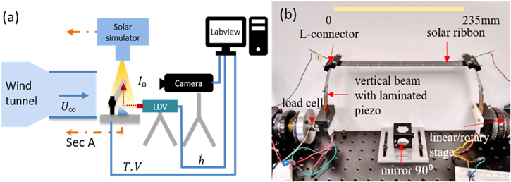
Figure 1. Experimental setup for simultaneous wind and solar characterization of the hybrid energy harvester (a) shows a schematic of the setup and (b) shows the sectional view A, such that wind flow direction is out of the page and solar illumination direction is from top to bottom of the image.
Download figure:
Standard image High-resolution imageExperiments are conducted using a low speed, low turbulence intensity (0.23%) wind tunnel having a maximum wind speed of ∼13 m s−1, test cross section of 25 × 25 cm, and an open jet blow-down configuration. A schematic of the experimental setup is shown in figure 1(a). A Polytec OFV 503 laser doppler vibrometer (LDV) is positioned downstream of the test apparatus, which along with a 90° mirror measures the velocity of the vibrating solar ribbon at its center span, center chord location. A Photron Fastcam AX 200 Mini high-speed camera with a Nikon 85 mm lens is positioned further downstream of the LDV, into the wind flow, to capture the deflection shapes of the vibrating ribbon. LDV velocity, the piezoelectric voltage across the resistive load, and load cell data are recorded using a National Instruments data acquisition system (NI 4661/4662, NI 4330). The high-speed camera is synchronized with the data acquisition and both are sampled at 2000 Hz. The solar illumination is provided by a solar simulator (Solar Light LS1000) with adjustable intensity, capable of producing full spectrum sunlight at one sun intensity (1000 W m−2). The solar intensity at the ribbon location is measured by a solar power meter (TES 132) and the solar power output of the ribbon is measured using a source-meter (Keithley 2450).
Before the data is collected, the preset static angle of attack α and the preload tension T, are set to the desired value by adjusting the linear/rotary stages at the legs of the harvester. Adequate time is allowed for the system to settle to static equilibrium and zero voltage is measured across the resistive load. The wind tunnel fan is engaged, and the flow is allowed to achieve steady state at a desired wind speed. The wind speed is measured using a hot wire anemometer (TSI Velocicalc 9535). The potentiometers are adjusted to the optimized resistance assuming a loosely coupled electro-mechanical system given by the equation [21] Ropt =1/2πfpCp, where fp is the predominant frequency of the measured piezoelectric voltage and Cp is the bimorph capacitance measured individually for each bimorph. The data is then acquired for a time duration of 30 s, during which the LDV velocity, and piezoelectric and load cell voltages are simultaneously recorded. The high-speed camera records the initial 2 s of synchronized data, which helps keep the saved data within the storage limits of the hard drive. The solar output is measured by generating i–V (current–voltage) curves at every test condition and determining the maximum power point from the curves.
The collected data is post processed using MATLAB, where a low pass filter is used to truncate the frequency content of the signals beyond 500 Hz. The filtered signal is parsed into smaller time segments of 1 s and the FFT and RMS voltages are evaluated on each time segment. Measurements are performed over 30 such time segments for every wind speed, averaged, and presented here.
Results and discussion
The standalone wind power output of the device is shown in figure 2. This figure captures the effect of changing α and applied preload tension across a range of wind speeds. The RMS power is averaged over several time segments, evaluated separately for each vertical piezo-beams and added together to get the total wind power output of the harvester. As expected, the power output increases with wind speed in general. However, for test cases corresponding to α = 10°, T = 3 N and α = 5°, T = 1 N, the general trend is violated. Considering a representative case of T = 1 N, α = 5°, it is observed that the RMS power increases gradually from the onset of LCO, with increasing wind speed. A sample wind speed of 8 m s−1 in this regime of operation is shown in figure 3, where the system is seen to oscillate with a single predominant frequency, shown by the distinct frequency peak in the FFT of the ribbon velocity and piezo voltage. Due to the motion kinematics of the structure, when the ribbon completes one cycle of motion, the vertical beams undergo two cycles (between zero and maximum displacement). This phenomena is similar to rectified signals but in the displacement domain for the vertical beams. Hence, the piezoelectric voltage records twice the predominant frequency than that of the ribbon. Beyond wind speed of 10 m s−1 the harvester transitions into chaotic/random vibration, where the velocity and voltage signals show multiple frequency content as observed for wind speed of 11 m s−1. Hence, this results in an overall reduction is the output RMS power beyond 10 m s−1. The synchronized high-speed camera images captured during the experiment provide further tangible insight into the physical behavior of the oscillations. In figure 4(a), the vertical sequence of images are equally spaced in time lying within the bounds shown by the red dashed lines in figure 3. At U∞ = 8 m s−1, the deflection shapes in the classical modal convergence flutter regime for one period of motion is shown to have a clearly discernable torsional deflection shape. At U∞ = 11 m s−1, the image sequence is devoid of a noticeable torsional shape and the ribbon intermittently falls out of the predominant periodic oscillation, resulting in an onset of multi-frequency motions. This results in redistribution of vibratory power from the predominant frequency to other frequencies which adversely affects the power output of the system.

Figure 2. Energy harvested from wind flow alone, as a function of wind speed for different values of preset angle of attack and preload tension.
Download figure:
Standard image High-resolution image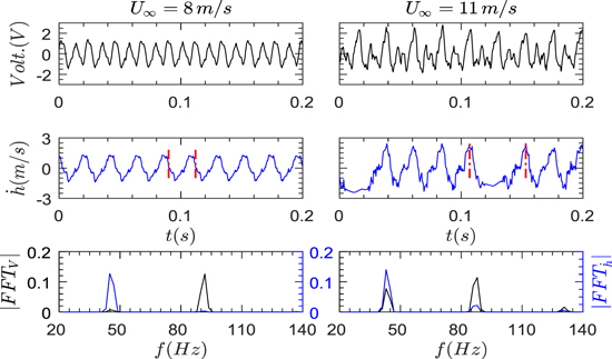
Figure 3. Variation in resistive load voltage and LDV velocity signal properties when the system transitions from stable LCO at 8 m s−1 (left) to chaotic motion at U∞ = 11 m s−1 (right) with T = 1 N, α = 5°.
Download figure:
Standard image High-resolution image
Figure 4. Monochrome images captured by high-speed camera for T = 1 N, α = 5° test conditions showing the transition from (a) stable LCO at wind speed 8 m s−1, to (b) chaotic/random motion at wind speed 11 m s−1. In both cases the sequence of images from top to bottom depict the motion sequence for one period of oscillation as shown within the red dashed lines of figure 3.
Download figure:
Standard image High-resolution imageAlso, notable to observe is the measured RMS power associated with T = 2 N, α = 5° which surpasses the other tested conditions throughout the tested wind speed range. As observed in figure 5, the solar ribbon with T = 2 N, α = 5° exhibits stable LCOs with a single predominant frequency and a gradual increase in peak voltage with increasing wind speeds over the entire range of wind speed tested, resulting in progressively increasing RMS power.
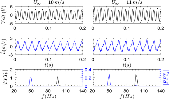
Figure 5. Load voltage history, velocity history, and frequency content measured at T = 2 N, α = 5° for two different wind speeds of 10 m s−1 (left), and 11 m s−1 (right).
Download figure:
Standard image High-resolution imageFigure 6 illustrates the evolution of the LCO phase portraits with increasing wind speed. The top row of the phase plots are plotted for T = 1 N, α = 5° and the bottom row for T = 2 N, α = 5°. The onset of LCOs in the system is marked by a conspicuous change in the shape of the phase portrait. For the two test cases shown here, self-sustained LCOs are observed when the wind speed is increased from 3 to 3.5 m s−1 and from 4 to 4.5 m s−1, respectively. The phase portrait changes from a solid disk to an annulus shape, simultaneously accompanied by a jump of several multiples in the magnitude of velocity and displacement. This behavior has been observed across the entire envelope of tensions and preset angles of attack considered. At higher wind speeds, the LCOs becomes increasingly random and chaotic and follows multiple trajectories as shown by the thicker phase portraits, devoid of a well-defined shape. It is important to note that even when the bounding limits of the LCO phase portraits are similar, the piezoelectric output power can be significantly different. An example of this behavior is seen for the cases of T = 1 N, α = 5° compared to T = 2 N, α = 5°. While the phase portraits seen in figure 6 are similar, the case with T = 2 N produces around three times the power output. The authors hypothesize that tuning the tension parameter plays an important role in the system performance which changes the stiffness match at the interface of different structural components (i.e. between the vertical bimorphs and the tensioned ribbon), thereby affecting the strain at the piezoelectric patch locations. The voltage signatures of the piezoelectric transducers are different for these cases and have a different frequency content as shown in figures 3 and 5, respectively. Detailed investigation into this phenomenon via analytical modeling with associated nonlinearities is the subject of future work.
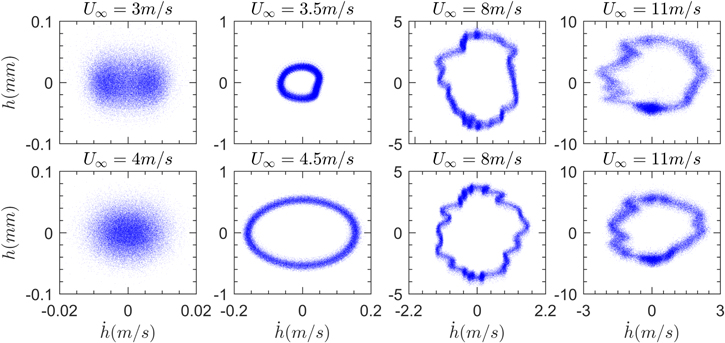
Figure 6. Phase portraits of LCO in the tensioned ribbon. The top row corresponds to T = 1 N, α = 5° and the bottom row corresponds to T = 2 N, α = 5°.
Download figure:
Standard image High-resolution imageThe flexible solar module used in this experiment consists of nine individual solar cells connected in series and packaged in a protective polyethylene coating. The solar light simulator has a beam area measuring 165 × 165 mm which covers ∼70% length of the solar ribbon or ∼8 individual cells. To obtain the total solar output assuming complete illumination of the entire ribbon, the voltages of the remaining 4 cells are added linearly along the voltage axes of current–voltage curves [22]. Since all these experiments are performed at a spatially averaged irradiance, I ≅ 680 W m−2, owing to the positioning of the solar simulator above the wind tunnel, estimating the maximum power output at different irradiance levels means shifting the current–voltage curve along the current axis proportionately to the required irradiance level [22] to obtain the modified short circuit current. These simple extrapolations are sufficiently accurate for estimating the solar power output and establishing the capabilities of the hybrid energy harvester.
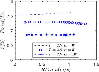
From figure 7, the transduction efficiency of the solar module is found to be around 7%, which is typical for such commercially available flexible modules. Vibration velocity in addition to ambient wind speed leads to convective cooling which increases solar efficiency [22, 23] and also induces a time-varying incidence angle of the solar module to the incident irradiance. It is hypothesized that these competing phenomena interact such that the solar efficiency remains virtually invariant with increasing vibration velocity as observed in figure 7. Detailed investigation into this phenomenon is a topic of future work.
Figure 7. Efficiency of solar power output as a function of RMS vibration velocity at mid-span, mid-chord location, measured at T = 2 N and different angle of attack values with wind speed 5 ≤ U∞ ≤ 12 m s−1.
Download figure:
Standard image High-resolution image
Solar energy comparable to the wind energy could be harvested for situations which call for the device to be placed in shaded environment instead of direct sunlight, for example under bridges or on the side of buildings devoid of direct solar irradiance. Considering a solar irradiance range within 30–100 W m−2, wind-off solar power output varies within 1.2–9.7 mW, which is of the same order of magnitude as the harvested wind power.
Conclusion
In this letter, an experimental investigation has been carried out to gauge the energy harvesting capabilities of a novel wind-solar hybrid energy harvester, using a flexible solar module as the primary element for capturing both solar and wind energy. Piezoelectric patches provide the electro-mechanical transduction, as opposed to the more commonly used electromagnetic transduction, which simplifies assembly and makes the device more compact. The un-optimized proof of concept device can generate a solar power output of 10.8 mW (at 100 W m−2 irradiance) along with 1.3 mW of wind power at 12 m s−1 flow speed. This is sufficient for low powered electronic applications like wireless sensor nodes. This investigation also provides high-speed camera imagery of the vibrating tensioned ribbons in cross-flow and reveals the evolution of phase portraits, from a solid disk at wind speeds below the onset of LCO, to an annular disk during stable LCO with a single predominant frequency, to aperiodic/random motions with multiple frequency content at higher wind speeds. The experimental results also demonstrate that the flow-induced vibration of the ribbon and wind energy harvesting do not negatively affect the solar energy harvesting performance of the flexible photovoltaic module but provide additional energy scavenging. Future work will include mechanical impedance matching at the interface of the structural components to achieve optimized transfer of aeroelastic vibration energy into the piezoelectric transducers, as well as power electronics design to combine and regulate the electrical output.
The authors gratefully acknowledge funding support for this research from the National Science Foundation under Award No. CMMI-1435077 and program officers Massimo Ruzzene and Atul G Kelkar.