
Abstract
This paper deals with Cu agglomeration and diffusion that occur in Cu thin films during annealing in supercritical CO2. Cu was deposited by using direct current magnetron sputtering on trench-patterned substrates. Annealing was performed in different atmospheres, namely, pure CO2, CO2 mixed with H2, CO2 mixed with hexafluoroacetylacetone (Hhfac), and CO2 mixed with H2 and Hhfac. The conspicuous agglomeration of Cu films was observed after annealing in the H2-mixed supercritical CO2. This is because Cu diffusion is accelerated by reduction and oxidation that proceed simultaneously on the Cu surface.
Export citation and abstract BibTeX RIS
1. Introduction
Supercritical fluids are high-pressure and sometimes high-temperature fluids beyond the critical pressure and temperature, respectively. Since supercritical fluids have a density as high as that of a liquid, they show a superior capability to dissolve materials. Furthermore, supercritical fluids have large fluidity as high as that of a gas because of their zero surface tension, larger diffusivity, and lower viscosity than a liquid. From these characteristics, supercritical fluids easily penetrate deep into porous nanostructures and deliver dissolving solutes at a large mass flux. In this study, we used supercritical CO2 (scCO2) (the critical temperature and pressure of which are 31 °C and 7.38 MPa, respectively1)). These moderate temperature and pressure conditions are advantageous for industrial applications.
Supercritical fluid chemical deposition (SFCD) has been successfully applied to metal filling in extremely high-aspect-ratio nanostructures,2–6) and it is expected as a future metallization technique. In Cu SFCD, an organometallic Cu compound is reduced through a reaction, for example, Cu(hfac)2 + H2 → Cu + 2Hhfac (hfac: hexafluoroacetylacetonate, Hhfac: hexafluoroacetylacetone).7–10) Other Cu organometallic compounds,11–13) such as bis(tetramethylheptanedionate)copper [Cu(tmhd)2]4,7) and bis(diisobutyrylmethanate)copper [Cu(dibm)2],14–17) can deposit metals through a similar process.
When Cu was deposited in a Cu-seeded narrow trench by SFCD, the deposited Cu coalesced with an underlying thin Cu (seed Cu) film.17) This was accompanied by Cu agglomeration and grain coarsening as well as void formation at the Cu/barrier interface. The deposition temperature of SFCD was as low as 200 °C, which is much lower than the reported agglomeration or reflow temperatures of Cu thin films.18–20) Also, Ueno and coworkers studied the grain size of Cu during annealing in scCO2 and observed grain growth acceleration when scCO2 was mixed with H2.21,22) This is very interesting, as SFCD is carried out in a reductive environment, as stated above. In terms of the novelty of the application of supercritical fluids to large-scale integration (LSI) processing, the stability of Cu in a supercritical environment is a crucial subject to study. In this work, we studied the effects of annealing environments on the agglomeration of Cu thin films.
2. Experimental procedure
Figure 1 shows a schematic diagram of the equipment used for scCO2 annealing. A flow-type system was used, where CO2 and additives were supplied at a constant flow rate at constant temperature and pressure. Details of the reaction system are given elsewhere.10,14,23)

Fig. 1. Schematic diagram of the equipment used for scCO2 annealing.
Download figure:
Standard image High-resolution imageFour different environments were used for annealing, namely, pure CO2 (scCO2 hereinafter), H2-mixed CO2 (scCO2 + H2), Hhfac-mixed CO2 (scCO2 + Hhfac), and H2- and Hhfac-mixed CO2 (scCO2 + H2 + Hhfac). Hhfac is a byproduct of a Cu SFCD reaction (see above) and was therefore added to investigate its effect. Liquid CO2 was supplied to the system and was pressurized to 10 MPa. The preheater was heated to 150 °C, and the reactor was heated to a target temperature with heating mantles. The reactor temperature and pressure were higher than those of the critical point of CO2 so that CO2 was a supercritical fluid. The specimen was placed in a stainless-steel tube, and the tube was heated to a set temperature (140–300 °C). Gaseous H2 (1.0 MPa) was injected to CO2 using a hydrogen mixer and liquid Hhfac was injected using a high-pressure pump. The concentrations of H2 and Hhfac were 0.1 mol ratio to CO2 and 1.8 × 10⁻⁵ mol ratio to CO2, respectively. This fluid was then preheated using the preheater and was supplied to the reactor, which was controlled by a back-pressure regulator. The reactor, the preheating system, the gas mixing unit, and other related piping and valves were maintained at 40 °C in a thermostatic chamber. The annealing time was fixed at 60 min.
Trench-patterned SiO2/Si and unpatterned Ta/SiO2/Si and glass were used as substrates. The trench widths ranged from 10 to 100 nm. Cu was deposited by using conventional direct current magnetron sputtering without any substrate bias or temperature control. The thickness of the Cu films was varied from 30 to 250 nm. After Cu sputtering, the specimens were exposed to the atmosphere, and annealing was carried out in different environments. After annealing, the sample surfaces and cross sections were observed using scanning electron microscopy (SEM) and transmission electron microscopy (TEM). Surface roughness was evaluated using atomic force microscopy (AFM). Chemical composition was analyzed using energy dispersive X-ray spectrometer equipped with a scanning transmission electron microscope (STEM–EDX). The samples for cross-sectional TEM and STEM observations and analyses were prepared by a focused ion beam method using Ga ions.
3. Results and discussion
3.1. Cu agglomeration and diffusion in scCO2 + H2 + Hhfac
Figure 2(a) shows a cross-sectional SEM image of a 150-nm-wide trench after sputtering a Cu thin film of 150 nm thickness. The Cu film showed a uniform thickness on the substrate surface. On the sidewall of the trench, the Cu film was extremely thin and its thickness decreased with depth. The coating depth was approximately 200 nm from the top of the trench. The presence of Cu at the bottom of the trench is not very clear from this SEM image. These results well demonstrates the poor step coverage and shadowing effect in conventional sputtering.

Download figure:
Standard image High-resolution image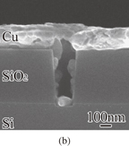
Fig. 2. Cross-sectional SEM images of Cu thin films deposited to a nanotrench (a) before and (b) after annealing in scCO2 + H2 + Hhfac environment.
Download figure:
Standard image High-resolution imageFirstly, we show the results of an annealing run in the scCO2 + H2 + Hhfac environment, because this environment is closest to the SFCD environment. The result is shown in Fig. 2(b). After the annealing, Cu was clearly observed on the sidewall and at the bottom of the trench. The Cu film on the sidewall and at the bottom was granular and discontinuous. This means that Cu diffused toward the trench bottom and agglomerated.
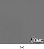
Figure 3 shows SEM images of the surfaces of Cu films (a) before and (b) after the annealing in the scCO2 + H2 + Hhfac environment. A smooth Cu surface was observed before the annealing [Fig. 3(a)]. Clearly rough surface of the Cu films was confirmed after the annealing [Fig. 3(b)]. This result is in agreement with the cross-sectional observation [Fig. 2(b)].
Download figure:
Standard image High-resolution image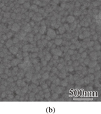
Fig. 3. SEM images of surface of Cu films (a) before and (b) after annealing in scCO2 + H2 + Hhfac environment.
Download figure:
Standard image High-resolution imageWe previously reported Cu agglomeration after Cu deposition on a Cu-seed layer by SFCD.17) The present results shown here clearly indicate that the agglomeration occurs regardless of the presence/addition of the precursor or the Cu deposition reaction.
3.2. Effects of annealing atmosphere on agglomeration and diffusion
To investigate the factors that induce the Cu agglomeration in scCO2, Cu films were annealed in different environments: (pure) scCO2, scCO2 + H2, and scCO2 + Hhfac. Figures 4 and 5 show cross-sectional and top-view SEM images of Cu films annealed in the (a) scCO2, (b) scCO2 + H2, and (c) scCO2 + Hhfac environments. The annealing temperature was fixed at 240 °C. The Cu film thicknesses before the annealing were approximately 250 nm for annealing in the scCO2 and scCO2 + H2 environments and 150 nm for annealing in the scCO2 + Hhfac environment. (Note that, as described in Sect. 3.4, the initial Cu film thickness does not influence diffusion and agglomeration when the Cu film thickness is larger than 60 nm.)

Fig. 4. Cross-sectional SEM images of Cu films annealed in (a) (pure) scCO2, (b) scCO2 + H2, and (c) scCO2 + Hhfac environments.
Download figure:
Standard image High-resolution image
Fig. 5. Top-view SEM images of Cu films annealed in (a) scCO2, (b) scCO2 + H2, and (c) scCO2 + Hhfac environments.
Download figure:
Standard image High-resolution imageEven after the annealing in scCO2, the Cu film surface was relatively smooth [Figs. 4(a) and 5(a)]. When Cu films were annealed in the scCO2 + H2 environment, granulated Cu was clearly formed on the sidewall and at the bottom of the trench [Fig. 4(b)]. Cu films on the substrate surface also agglomerated and void formation was observed [Fig. 5(b)].
When the annealing was performed in the scCO2 + Hhfac environment, an extremely small amount of Cu existed on the sidewall and at the bottom of the trench [Fig. 4(c)]. This result indicates that less diffusion and agglomeration occurred in the trench than in the case of annealing in the scCO2 + H2 environment. Even so, the Cu film surface became very discontinuous and numerous grooves were formed [Fig. 5(c)] as markedly as in the case of annealing in the scCO2 + H2 + Hhfac. The groove formation without remarkable Cu diffusion suggests a chemical role of Hhfac. Hhfac etches metal oxides,24–26) and we speculate that the Cu grain boundaries were etched away by Hhfac. (The origin of oxygen is discussed later.) From these observations, we concluded that hydrogen most strongly affected the Cu agglomeration in scCO2.
3.3. Roles of oxidation and reduction in Cu agglomeration
Figure 6 shows (a) a cross-sectional TEM bright-field image and (b) a STEM–EDX map of the granulated Cu formed by annealing in the scCO2 + H2 environment. The microstructure of the granulated Cu was not uniform, and a high-contrast structure with an approximately 10-nm-thick was covered low-contrast structure [Fig. 6(a)]. STEM–EDX analyses revealed that the high-contrast part is Cu and the low-contrast part consists of Cu and O [Fig. 6(b)]. That is, the granulated Cu was covered with an oxide film having a thickness of approximately 10 nm. Interestingly, the oxidation layer was also formed at the Cu/substrate interface. This strongly suggests that O incorporation/oxidation and Cu agglomeration occur concurrently, such like a Cu "droplet" traveled on the substrate surface with "flouring" itself with oxygen.

Download figure:
Standard image High-resolution image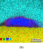
Fig. 6. Cross-sectional (a) TEM bright-field image and (b) STEM–EDX map of a granulated Cu formed by annealing in scCO2 + H2 environment.
Download figure:
Standard image High-resolution imageThe significant increment in Cu film roughness during annealing in scCO2 can be ascribed to the oxidation and reduction of the Cu film surface. When the oxidation and reduction on the Cu film surface compete, many vacancies are generated at the Cu surface. Since vacancies easily diffuse into the Cu film, the diffusion coefficient becomes large at the Cu surface. This large diffusion coefficient and the poor wettability of the Cu/glass interface result in agglomeration of Cu film. Through this diffusion process, oxygen is accumulated at the Cu surface and the Cu/substrate interface. It was reported that the oxygen content in metal films increases when H2O exists in scCO227,28) and that reduced Cu particles easily agglomerate.29)
The oxygen source is considered to be impurities that existed in CO2 and residual O2 and H2O in the deposition system. H2O is produced also by a reaction between CuO and H2. When Hhfac is mixed, H2O is generated by reaction between CuO and Hhfac: CuO + 2Hfhac → Cu(hfac)2 + H2O.26) An etching reaction can occur between CuO and Hhfac, and this also results in the generation of vacancies and roughness increment. However, its extent is less than that in the presence of H2.
3.4. Critical film thickness for Cu agglomeration or temperature effect
The annealing temperature dependence on the agglomeration in scCO2 + H2 environment is shown in Fig. 7. When the annealing temperature was 150 °C [Fig. 7(a)], agglomeration of Cu was less intensive and surface roughness was similar to that of the as-sputtered Cu film. Void formation was observed at the Cu surface at 200 °C [Fig. 7(b)]. At 300 °C [Fig. 7(c)] larger agglomerates were observed and the substrate surface was observed.

Download figure:
Standard image High-resolution image
Download figure:
Standard image High-resolution image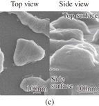
Fig. 7. Top-view and cross-sectional SEM images of Cu films annealed in scCO2 + H2 environment at (a) 150, (b) 200, and (c) 300 °C. The Cu thickness before the annealing is 30 nm. The top and side surfaces of the substrate is indicated.
Download figure:
Standard image High-resolution imageThe relationships among annealing temperature, surface roughness, and Cu thickness before annealing are shown in Fig. 8. When the thickness of Cu was larger than 60 nm, the surface roughnesses after the annealing were almost the same; 60 nm is a critical thickness below which interfacial diffusion dominates the film agglomeration. The film surface roughness increased markedly at temperatures above 200 °C. This temperature is lower than that used in a conventional reflow process.30,31) It is possible that scCO2 processes can ease the thermal budget of LSI backend processes owing to not only the metal filling capability of SFCD but also the temperature lowering of Cu diffusion.

Fig. 8. Relationships among annealing temperature, surface roughness, and Cu thickness before annealing.
Download figure:
Standard image High-resolution image
In this study, the effect of the substrate on Cu agglomeration was not very clear. Cu agglomeration is influenced by the wettability of Cu and the substrate used.32) In this study, glass and Ta/SiO2/Si were used as substrates (Fig. 8). Generally, the agglomeration is assumed to occur easily because of less interaction between inert glass and Cu. Since the Ta surface used in this study was oxidized (in supercritical processing, a substrate that is conveyed in a vacuum environment cannot be used), it is considered that there was no strong substrate dependence.
4. Conclusions
We examined possible factors that influence Cu film agglomeration during SFCD. Cu film agglomeration occurred regardless of the presence/addition of the precursor or the Cu deposition reaction. Large film agglomerates were observed when sputtered Cu was annealed in H2-mixed scCO2. The effects of scCO2 itself or a reaction byproduct of SFCD were not very significant. STEM–EDX analyses revealed that the agglomerated Cu was covered with a thin oxide film. It is assumed that Cu film agglomeration is accelerated when the reduction and oxidation of Cu proceed concurrently. The agglomeration became significant as the temperature increase and was enhanced markedly at temperatures above 200 °C. The agglomeration temperature in scCO2 is significantly lower than that in a conventional reflow process.
Acknowledgment
This research was financially supported by a Grant-in-Aid for Young Scientists (B) (25820122) from the Japan Society for Promotion of Science (JSPS).