

Abstract
The formation of multiple stationary striations between a nozzle exit and a conductive target plate was clearly observed at regular intervals using a digital camera along an atmospheric pressure plasma jet of dielectric barrier discharge using a neon gas into ambient air. From the results of measuring using a high-speed camera during the positive current phase, the emission initially started in the middle between the nozzle and the target, and striations progressed in both upward and downward directions. During the negative current phase, the emission initially started in a region near the target, and the striations rapidly progressed to the nozzle.
Export citation and abstract BibTeX RIS
Atmospheric pressure plasmas at low temperatures have been attracting considerable research attention as a promising plasma source for many application fields. For example, these plasma sources are widely studied and used as tools for chromatographic or electrophoretic1) analyses, surface modification of materials,2–6) and medical applications.7–11) Among the various atmospheric pressure plasmas that have been developed recently, the atmospheric pressure plasma jet (APPJ) in particular has shown a major potential for industrialization because it can provide sufficient numbers of reactive species and charged particles on the surfaces of target materials. In the APPJ, reactive species are produced not only inside the equipment, but also between the nozzle exit and the target material. The production mechanism of reactive species of the APPJ has been measured by several kinds of diagnostics,12–14) and studied by numerical simulations,15–17) but still not fully understood. Therefore, it is very important to study the plasma physics along the APPJ. It was previously reported that a plasma bullet was ejected from the APPJ nozzle into ambient air where the plasma was produced by a dielectric barrier discharge, and was considered as the propagation of an ionization front.18–21) In this report, to understand the processes of plasma interaction with the target material, the spatiotemporal behavior of the emission is studied using a high-speed camera.
Figure 1 shows a schematic drawing of the experimental setup for the plasma equipment and the measurement system. This plasma equipment has been specially designed for blood coagulation using a low-energy APPJ.22,23) The plasma flare is ejected from a quartz tube with an inner diameter of 1.4 mm into ambient air. The plasma equipment is composed of the dielectric barrier discharge plasma source with three sets of electrodes, and a high-voltage power supply based on piezoelectric materials has been used to produce the plasmas. The peak-to-peak voltage (Vp-p) is controllable from 0.0 to 10.0 kV with a sinusoidal frequency of 61.7 kHz, and is applied to the high-voltage electrode attached to the outer surface of the quartz tube. The working gas flow rate, Q, for neon (purity: 99.999%) flowing through the quartz tube was controlled in the Q = 0.0 to 4.0 L/min range using a mass flow controller. A shunt resistance of 50 Ω was used in the circuit for measurement of the current to the grounded copper target plate. The 12-bit high-speed camera (nac Image Technology Ultra Neo) was used to capture time-resolved images of the plasma emission in the APPJ.
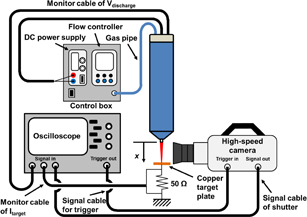
Fig. 1. Schematic drawing of the experimental method. Plasma equipment with control box, and diagnostic system composed of a high speed camera, a copper target plate for current measurement, and an oscilloscope are illustrated. x is the distance between the nozzle exit and the target plate.
Download figure:
Standard image High-resolution imageInitially, an image of the time-integrated neon plasma flare between the nozzle exit and the copper target plate was measured using a digital single-lens reflex camera (Canon EOS 7D), as shown in Fig. 2. The image was taken using an exposure time of 125 µs, which means that the image contains about eight cycles of a sinusoidal applied voltage, as shown in Fig. 3. Multiple stationary striation phenomenon was clearly observed with regularity along the plasma flare, rather than with bullet propagation. Here, Vp-p = 6.0 kV, Q = 2.0 L/min, and x = 9 mm, where x is the distance between the nozzle exit and the target plate. This image proves that the striated emissions are produced at the same location, and does not move up and down during the measurement. Namely, the striation phenomenon has high reproducibility. Strong line emissions of Ne I around the 600 nm wavelength region were confirmed along the plasma flare by visible spectroscopic measurement. On the other hand, the striations have already been observed in previous studies using various atmospheric pressure plasmas, such as glow discharges,24–26) microwave-excited discharges,27) hollow cathode plasmas,28) and asymmetric barrier discharges.29) In previous APPJ studies, the striation phenomena were also reported.30–33) The emission intensity of each striation deceased along the APPJ, as the distance from the plasma source increased.30–32) In particular, Hong et al.30) and Seo et al.32) reported that the distance between striations changed as the distance from the plasma source increased. Kang et al.31) reported that the striation phenomenon was observed only by adding a small percentage of oxygen gas to the argon working gas. However, in this study on the clear striation phenomenon, the following characteristics are observed; multiple striations are 1) stationary with high reproducibility and 2) arraigned at regular intervals over the APPJ to the target. Hereafter, the stationary striation phenomena along the plasma flare are studied using a high-speed camera in terms of their dependencies on the gas flow rate, the applied voltage to the electrode, and the difference in the target material.

Fig. 2. (Color) Photograph of the Ne APPJ taken with a digital single-lens reflex camera (Canon EOS 7D). The camera exposure time was 125 µs. The locations of the nozzle exit and the copper target plate are indicated.
Download figure:
Standard image High-resolution image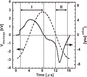
Fig. 3. Time evolution of the discharge voltage applied to the electrode (Vdischarge), and the current flowing towards the target plate (Itarget), which was placed at x = 16 mm.
Download figure:
Standard image High-resolution imageFigure 3 shows the waveforms of the discharge voltage applied to the electrode, Vdischarge, and the plasma flare current, Itarget, that flows to the ground through the copper target plate in a single cycle. In the rising phase of the voltage waveform, the current is positive, i.e., the positive ions flow towards the target plate. In contrast, in the falling phase of the voltage waveform, the current is negative, i.e., negative species flow towards the target plate. Here, Vp-p = 6.0 kV, Q = 2.0 L/min, and x = 16 mm. It is only possible to observe emissions using the high-speed camera during the periods (I) and (II), as shown in Fig. 3.
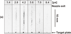
Figure 4 shows intensified charge-coupled device (ICCD) images of the neon APPJ taken by the high-speed camera with an exposure time of 200 ns. The discharge conditions are the same as those used in Fig. 3. The target current for a positive rise is used as the trigger signal. As shown in Fig. 4(a), which corresponds to phase (I) in Fig. 3, the evolution of the striations over time has been observed. First, it was found that the target surface is emitting independently with the striations extending to the nozzle exit. This target surface emission seems to be continuously maintained during the positive current phase. Then, in the middle section, the striations progressed in both the upward and downward directions. This indicates that the process of APPJ emission development is not simply propagation from the nozzle exit to the target plate. As shown in Fig. 4(b), which corresponds to phase (II) in Fig. 3, the evolution of these striations over time has also been observed. The emission initially started in a region near the target, and rapidly progressed in the nozzle direction. However, no emission was observed near the target plate. The emission period (7.2 µs) during the positive phase is almost twice as long as that during the negative phase.
Download figure:
Standard image High-resolution image
Fig. 4. ICCD images of the neon APPJ taken with the high-speed camera at different times. The exposure time for each frame was 200 ns. The applied maximum peak-to-peak voltage was 6.0 kV, and the neon gas flow rate was 2.0 L/min. The copper target plate was placed at x = 16 mm. (a) Emission images every 1.4 µs during period (I) in Fig. 3, and (b) emission images every 600 ns during period (II) in Fig. 3.
Download figure:
Standard image High-resolution imageFigure 5 shows ICCD images (exposure time = 1.39 µs) of the neon APPJ with the copper target at x = 16 mm. A reason for setting the exposure time at 1.39 µs is to be able to take one cycle of emission in twelve successive photographs at once (total, 1.39 µs × 12 = 16.68 µs). The neon gas flow rate dependencies on striation are studied, as shown in Fig. 5(a), in the case where Vp-p = 6.0 kV for flow rates of 2.0, 3.0, and 4.0 L/min. (I) and (II) in Fig. 5 indicate the relevant periods during the positive and negative current phases, respectively. As the flow rate increases, the striated area is shifted slightly towards the target plate. The distance between individual striations remained unchanged, and was approximately 0.6 mm. The dependencies of the applied voltage to the electrode are studied, as shown in Fig. 5(b), in the case where Q = 2.0 L/min for Vp-p = 2.5, 3.9, and 6.0 kV. In the case where Vp-p = 2.5 kV, no plasma emissions were observed during the negative current phase. It was however noted that as the applied voltage increased, the number of striations also increased. Again, the regular distance between the striations was approximately 0.6 mm.
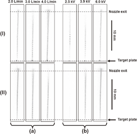
Fig. 5. ICCD images of the neon APPJ taken with the high-speed camera under various conditions. The exposure time of each frame was 1.39 µs. (I) and (II) show the periods at the positive and negative peak target currents, respectively. The target plate is placed at x = 16 mm. (a) Neon gas flow rate dependencies for flow rates of 2.0, 3.0, and 4.0 L/min at an applied voltage of 6.0 kV to the electrode. (b) Dependencies of applied voltage to the electrode at voltages of 2.5, 3.9, and 6.0 kV at a neon gas flow rate of 2.0 L/min.
Download figure:
Standard image High-resolution imageFigure 6 shows ICCD images (exposure time = 1.39 µs) of the neon APPJ in the case where Vp-p = 6.0 kV and Q = 2.0 L/min. Figures 6(a) and 6(b) show the case without the target plate and the case in which the target plate is covered by a polyamide dielectric. (I) and (II) in Fig. 6 indicate the relevant periods during the positive and negative current phases, respectively. Note here that the image contrast was adjusted, because the emission intensities are low. In phase (I), striations were observed along the plasma flare in both cases. While in phase (II), emissions were not clearly observed. Therefore, the images indicate that the conductive target plate is one of the important factors for inducing strong striated phenomena in the APPJ.

Fig. 6. ICCD images of the neon APPJ taken with the high-speed camera under different conditions. The exposure time for each frame was 1.39 µs. The applied maximum peak-to-peak voltage was 6.0 kV, and the neon gas flow rate was 2.0 L/min. (I) and (II) show the periods at the positive and negative peak target currents, respectively. (a) Images taken without the target plate. (b) Images taken when the copper target was covered with a dielectric material (polyamide), and the target was placed at x = 16 mm.
Download figure:
Standard image High-resolution image
As shown in Fig. 4, it is clear that the plasma produced in the plasma source of the APPJ was not ejected into ambient air with the flow of neutral particles, and the ionization was formed outside of the quartz tube. In these experiments, important features were obtained, which led to the clarification of the striation phenomena. First, the striations were related to the amplitude of the applied voltage to the electrode and the distance between the nozzle exit and the target, but not to the flow rate of the neutral gas. Second, the multiple stationary striations are spaced at equal intervals. Third, during the positive current phase, the emission initially started in the middle between the nozzle and the target, and the striations progressed in both upward and downward directions. During the negative current phase, the emission initially started in a region near the target, and the striations rapidly progressed to the nozzle exit.
From these characteristics, the striation phenomena in Ref. 29 can be selected from the viewpoint of their similarities, even though the experimental setup is completely different. In that paper, the striation phenomena were also studied by numerical calculations, and it was believed that local electric field modulations, as indicated in Eq. (4) of Ref. 29, are important. Additionally, in Ref. 26, atmospheric pressure glow discharges were studied, and it was noted that a local electric field was a prerequisite for striation formation.
Incidentally, the phenomenon in which a strong emission only occurs near the target surface during the positive current phase indicates that high-energy electrons are produced around the target surface region owing to sheath effects.34,35) Indeed, the production rates of the reactive species increased around the target surface region.36)
In conclusion, multiple stationary striation phenomena were clearly observed along the neon APPJ between the nozzle exit and the copper target plate using the digital camera. It was noted using the high-speed camera that during the positive current phase, the emission initially started in the middle between the nozzle and the target, and the striations progressed in both upward and downward directions. During the negative current phase, the emission initially started in a region near the target, and the striations rapidly progressed to the nozzle exit. The feature of the stationary striation depends on the amplitude of the applied voltage to the electrode and target species. Additional information is required to understand the dynamics of the low-energy APPJ, and may require various types of diagnostics to measure the local distributions of reactive species, electron density, and temperature along the plasma flare.37) This multiple striation phenomenon would be quite effective for studying the striation mechanism, because they are stationary.
Acknowledgment
This study was supported by a Grant-in-Aid for Scientific Research on Priority Areas (24108006) from the Ministry of Education, Culture, Sports, Science and Technology of Japan.