

Abstract
The fabrication of nanogratings usually requires expensive equipment such as electron beam lithography. Here, a novel and simple method of fabricating nanogratings is presented by contracting the prestretched polydimethylsiloxane (PDMS) substrate adhered a unstretched PDMS micrograting film which is obtained by replicating the template fabricated from less expensive laser beam lithography. Additionally, a PDMS gradient-pitch nanograting is successfully fabricated by adhering a unstretched micrograting PDMS film onto a prestretched wedge-shaped PDMS substrate. The proposed method shows great promise in optical applications requiring cost-effective and accurate nanogarings and filters.
Export citation and abstract BibTeX RIS
1. Introduction
Nanogratings have many potential applications in optical filters,1) biological sensors,2) fluorescence extraction,3) Roman enhancement,4) and similar fields. Various nanograting preparation schemes, such as photolithography,5) electron beam lithography,6) focused ion beam lithography.7) dry and/or wetting etching,8,9) nanoimprint,10) and soft imprint lithography11) have been widely reported. Although the nanogratings by direct-write electron beam lithography are of high quality, but the fabrication cost is very high and the fabricating is quite time-consuming. Therefore, a great deal of research has been conducted to develop simple and low-cost techniques for fabricating various nanogratings. The nanoimprint and soft imprint lithography have been recognized as cost-efficient nanopattern preparation methods because of their ability to facilely transfer the nanopattern onto other materials over a large area with high productivity. However, when using these methods, each new nanopattern requires a new nanopattern mold or even a new master for the mold, and fabricating these nanopattern molds and masters is very expensive. Therefore, a more cost-effective method for the fabrication of nanostructure masters and molds is desirable.
Some size reduction lithography (SRL) techniques have been presented as methods to overcome the resolution limitation of the conventional photolithography technique,12–14) which can be used to fabricate a new mold using the original mold. Reference 15 presented a method of SRL using photolithography together with chemical vapor deposition (CVD) and selective etching. This method, also called spacer lithography, deposited silicon oxide onto the sidewall of the one-dimensional grating ridge using the CVD technique, then etched the ridge using selective etching. As a result, the grating period was reduced by 50% with a single cycle of SRL. By repeating the SRL cycle several times, the width of the grating line can be made as narrow as several nanometers.15) Additionally, the use of spacer lithography has also been demonstrated with pressure-assisted selective wetting and thermal reflow.13) Although the spacer lithography method substantially overcomes the limitations of photolithography techniques, the SRL manufacturing technique is complicated and expensive, limiting the application of this method. More importantly, spacer lithography cannot successively tune the size of the nanopattern or fabricate a gradient-period nanopattern.
Recently, some researchers have demonstrated that nanoimprint lithography using only a nanopattern mold can continuously adjust the nanopattern size for a new mold.16,17) Reference 17 used a silicon master with a one-dimensional grating structure to imprint a stretchable temperature-memory polymer. The temperature-memory polymer with the one-dimensional grating was gradually and unidirectionally contracted at an appropriate temperature. During this contraction process, the groove width could be significantly reduced while maintaining a constant ridge width, providing a sizeable increase in the depth-to-width ratio. Although this method was shown to effectively and successively tune the grating groove width using temperature control, the incorrect temperature selection can lead to the collapse of the nanopattern. As a result, the use of nanopatterned temperature-memory polymer is not applicable to a replication process using thermal imprint lithography. In contrast, nanoimprinted photosensitive tin(II) 2-ethylhexanoate and photosensitive zirconyl 2-ethylhexanoate films tune the size of the nanopattern ridge via the removal of organic groups and the resulting increase in the densification of the grating film under UV irradiation and annealing treatment.15,16) This method can reduce the grating ridge width using the annealing temperature. However, the removal of organic groups and the resulting increase in densification lead to an increase in the grating groove width and a constant period, along with a decrease in the grating depth. Although the above-mentioned methods can fabricate various new nanopattern molds of different sizes using a mold of the specified size, only the grating groove width or ridge width can be reduced for a new mold through either method. This single-dimension adjustability of a new mold restricts the potential applications of these methods. Therefore, a novel approach for decreasing both the grating groove and ridge widths of a new mold needs to be explored.
Soft imprint lithography does not require the expensive facilities of nanoimprint lithography and employs a thermoplastic polydimethylsiloxane (PDMS) polymer with a low surface energy to facilely duplicate nanopatterns.18) Importantly, the PDMS material has many superior properties, including excellent flexibility and high transparency in the visible wavelength range. These superior properties have been widely used to tune the grating period using various methods, such as dielectric elastomer actuators,19) mechanical stress,20) and microfluidics.21,22) However, these methods generally incur an increase in the grating period or cause the grating to enlarge, recovering to its original state, meaning that the original period of the grating still cannot be reduced. Furthermore, the effect of elongation on the grating geometry (i.e., the groove and ridge widths and the depth-to-width ratio) has seldom been analyzed systematically.
In this paper, a novel method is presented to decrease the one-dimensional PDMS grating period using flexible PDMS. The micrograting pattern was transferred onto the surface of a PDMS substrate prestretched to 160%, then the PDMS substrate contracted to 115% of its original length after the prestress was released. Scanning electronic microscopy (SEM) imagery shows that the groove width was reduced from 570 to 210 nm and that the ridge width was decreased from 430 to 370 nm. As a result, the grating pitch was significantly reduced from 1 μm to 580 nm, i.e., a reduction of 42%. Additionally, when the 1 μm pitch micrograting pattern was transferred onto the surface of a prestretched wedge-shaped PDMS substrate, a gradient-pitch nanograting varying from 640 to 490 nm was simply obtained.
2. Design and analysis
Figure 1 shows a schematic diagram of the proposed grating pitch reduction process. A rectangular PDMS substrate is prestretched from its original length l to l + Δl. A one-dimensional PDMS grating film with a pitch of T is then adhered onto the top of the core of the substrate. Next, the PDMS substrate is contracted to l + Δl − Δl' (where Δl > Δl'). The contraction ratio of the PDMS substrate is defined as the ratio ε between the contracted length and original length of the substrate, expressed as

and the reduction ratio of the PDMS grating pitch can be expressed as

where T' is the grating pitch after reduction. If the thickness of the PDMS substrate far exceeds that of the PDMS grating film, the difference in the elastic modulus of the PDMS substrate with and without the PDMS grating film can be neglected. Therefore, the reduction ratio (ν) of the PDMS grating pitch is equal to ε and the PDMS grating period after reduction can be expressed as

It can be found from Eq. (3) that the PDMS grating period after contraction decreases with the increase in the contraction ratio.
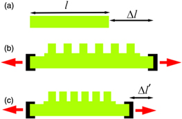
Fig. 1. (Color online) Schematic diagram of grating-pitch reduction process.
Download figure:
Standard image High-resolution image3. Experiment
Figure 2 shows the procedural diagram of the proposed grating-pitch reduction method. First, a photoresist mold with a 1 μm pitch grating [Fig. 2(a)] was prepared by using a noncontact and maskless laser direct writing system with the resolution of 0.9 μm and modified using trimethyl chlorosilane to facilitate the detachment of the PDMS from the photoresist mold. Subsequently, the PDMS prepolymer and its crosslink agent were mixed in a mass ratio of 10:1 and was spin-coated onto the photoresist mold [Fig. 2(b)]. After curing at 80 °C for 4 h, the PDMS micrograting was facilely detached from the photoresist mold [Fig. 2(c)], then imprinted on a liquid droplet of epoxy resin [Fig. 2(d)], again followed by curing at 80 °C for 4 h. The epoxy resin mold was obtained by directly detaching the PDMS grating [Fig. 2(e)], and used to cast a liquid PDMS film through spin-coating at 1000 r min−1 for 50 s [Fig. 2(f)]. Then the epoxy resin mold with the liquid PDMS film was transferred onto the surface of a prestretched PDMS substrate [Fig. 2(g)]. After baking at 80 °C for 4 h, the PDMS film was closely adhered to the PDMS substrate and the epoxy resin mold was directly detached from the PDMS film [Fig. 2(h)]. Finally, the stretchable PDMS substrate and the PDMS grating film were allowed to contract together, reducing the PDMS grating pitch [Fig. 2(i)].

Fig. 2. (Color online) Procedure of proposed grating-pitch reduction method.
Download figure:
Standard image High-resolution image4. Results and discuss
According to the analysis in the above paragraph, an increase in the contraction ratio is advantageous for PDMS grating pitch reduction. Clearly, maximizing the prestretch of the PDMS substrate can extend the contraction length and thus improve the upper limit of the contraction ratio, reflecting the grating pitch reduction capability of the method. To obtain the maximum contraction ratio, two tests were performed: (1) stretching the naked PDMS substrate to its utmost, and (2) allowing the prestretched PDMS substrate to gradually recover to its original length with the PDMS grating film attached. The experimental results show that a 1.1 mm thick PDMS substrate is easy to crack when it is elongated beyond 60%. This cracking is mainly the result of the sharp edges generated in the process of cutting the substrate. Additionally, the complete removal stress on the PDMS substrate results in the deformation of the PDMS grating, as shown in Fig. 3(a). To determine an appropriate contraction ratio, a 1.1 mm thick PDMS substrate was stretched to 160% of its original length and a 60 μm thick PDMS grating was adhered to it. Then the stretchable PDMS substrate with the PDMS grating was successively allowed to contract to 115%, 110%, 105%, and 100% of its original length, corresponding to contraction ratios of 45%, 50%, 55%, and 60%, respectively, as shown in Fig. 3. It can be seen in the figure that the geometric deformation increases with the increase in the contraction ratio of the PDMS substrate. This deformation can be explained by the following rationale. When the stress in the PDMS substrate with the PDMS grating film attached is reduced, the PDMS substrate contracts and the PDMS grating film is squeezed, causing a decrease in the grating pitch. As the contraction of the PDMS substrate proceeds, the stress (Fs) in the PDMS substrate decreases and the stress (Ff) in the PDMS grating film increases. When Fs is equal to Ff, the compression in the PDMS grating film is at a maximum. At this point, the PDMS grating film becomes incompressible and behaves similarly to a rigid film, causing the PDMS substrate to deform. Notably, the stretchable PDMS substrate then recovers to 115% of its original length and the deformation disappears, as shown in Fig. 3(d). As a result, in the experiments conducted in this study, the optimal elongation and contraction ratios of the PDMS substrate are 60% and 45%, respectively.

Fig. 3. (Color online) Photos of the PDMS substrate with the PDMS grating film at contraction ratios of 45%, 50%, 55%, and 60%.
Download figure:
Standard image High-resolution imageThe purpose of this study is to decrease the grating pitch in the film. Therefore, the grating geometry after contraction, as quantified by the groove and ridge widths, was investigated. Figure 4 shows SEM images of the cross-sections of one-dimensional PDMS gratings before and after contraction. The width and depth of the grooves in the one-dimensional, 1 μm pitch grating were 460 nm and 570 nm, respectively, before contraction, as shown in Fig. 4(a). After contracting 45%, the grating groove width decreased from 570 to 210 nm, and the ridge width decreased from 430 to 370 nm, as shown in Fig. 4(b). This clear inequality between groove and ridge contraction is due to the uneven elastic modulus between the groove and ridge of the PDMS grating. In the substrate zone with the PDMS grating film adhered, the nanopatterns lead to an inhomogeneity in the PDMS thickness. The elastic modulus at the location of a PDMS grating ridge is higher than that at a grating groove, causing the ridge to create a non-uniform stress that decreases with the increase in the height of the grating ridge. Consequently, the grating pattern of the PDMS grating film causes an inequality in its contraction-resistance capabilities at different locations. This is verified by a comparison between the grooves and ridges of the grating, in which the grooves can be observed to exhibit a more significant reduction in width than the ridges. In the experiment, both the grating groove and ridge widths exhibited clear reduction, indicating that the PDMS polymer behaves notably different than a temperature-memory polymer or photosensitive metal-organic compound.16,17) Additionally, due to the lack of stress in the direction perpendicular to the contraction, the groove depth in the gratings before and after contraction was the same. However, due to the significant decrease in the groove width, the nanopattern density was clearly increased, thus the depth-to-width ratio of the groove showed a considerable increase from 0.81 to 2.2. These increases are promising for potential applications in PDMS antireflective structures.23,24)

Fig. 4. SEM images of the cross-section of a one-dimensional PDMS grating before and after contraction. Scale bar: 500 nm.
Download figure:
Standard image High-resolution imageIn addition to examining the geometry of the PDMS grating after contraction, the pitch of the PDMS grating under different contraction ratios was investigated. To demonstrate the evolution in reduction of the PDMS grating pitch, a 60%-stretchable PDMS substrate with a 1 μm pitch grating film was successively allowed to contract to 150%, 140%, 130%, 120%, and 115% of its original length, corresponding to contraction ratios of 10%, 20%, 30%, 40%, and 45%, respectively. Figure 5 shows SEM images of the top view of these PDMS gratings. Clearly, reductions in both the ridge and groove widths result in a significant decrease in the grating pitch, mainly due to the contraction of the PDMS substrate together with the squeezing of the PDMS grating film.

Fig. 5. (a)–(f) SEM images of top of PDMS grating under different contraction ratios. Scale bar: 2 μm.
Download figure:
Standard image High-resolution imageIn order to quantify the relationship between the grating geometry and the contraction ratio, the ridge and groove widths and the pitch of the PDMS gratings were measured by SEM at different contraction ratios. The results show when the contraction ratio was linearly increased from 10%, 20%, 30%, 40%, to 45%, the ridge width decreased from 410, 394, 386, 377, to 370 nm, respectively, and the groove width decreased from 491, 403, 324, 245, to 210 nm, respectively, as shown in Figs. 6(a). Figure 6(b) shows that the grating pitches for contraction ratios of 10%, 20%, 30%, 40%, and 45% were 902, 805, 710, 622, and 580 nm, respectively, grating pitches for contraction ratios of 10%, 20%, 30%, 40%, and 45% were 902, 805, 710, 622, and 580 nm, respectively, indicating a reduction of 10%, 19%, 29%, 38%, and 42%, respectively. Clearly, the grating e reduction ratio is smaller than the contraction ratio of the PDMS substrate with the adhered PDMS grating film. The difference between the grating pitch reduction percentage and the PDMS contraction ratio can be explained as follows. Only a naked PDMS substrate can freely and repeatedly be stretched and recovered within its elastic limit. By adding a PDMS grating film on the top of a stretchable PDMS substrate, the grating film impedes the recovery of the substrate. In this case, this impedance leads to a slightly smaller contraction ratio in the zone where the PDMS substrate is adhered to the PDMS grating film. By contrast, the contraction ratio in the zone of the PDMS substrate without the PDMS grating film exhibits a slightly higher contraction ratio.
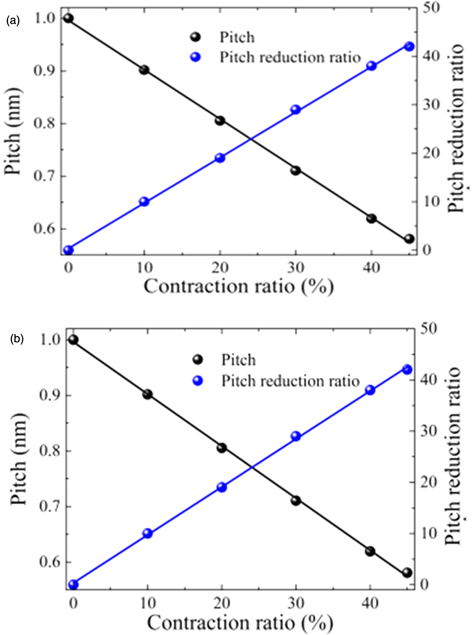
Fig. 6. (Color online) (a) Groove and ridge width, and (b) pitch and pitch reduction ratio of PDMS grating as a function of the contraction ratio.
Download figure:
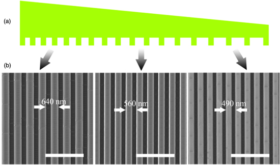
Standard image High-resolution imageIn order to further demonstrate the superiority of SRL with a flexible PDMS, a 1 μm pitch epoxy resin mold liquid-coated PDMS film was adhered to the top of a wedge-shaped 60%-stretchable PDMS substrate with end widths of 1.1 and 1.5 mm and a length of 50 mm before stretching. Figure 7(a) depicts a structural diagrammatic sketch of the nanopattern after contraction. Due to the wedge shape formed by the different end widths, the elastic modulus of the PDMS substrate varies with the position along its length, Δl, and can be determined according to Hook's law, F = kΔl, where F is the stress in the PDMS substrate and k is the elastic modulus. The elastic modulus therefore increases with the width of the PDMS substrate, and the elongation Δl can accordingly be recognized as a function of the width: the elongation at every location along the length of the substrate is different, so the contraction of the PDMS substrate is not constant. As a result, the PDMS grating pitch becomes a function of its position. To confirm this assertion, SEM images of a PDMS grating at three different locations of 0.5, 2.5, and 5 mm along its length are shown in Fig. 7(b). Clearly, the grating pitches at the three different locations are different. In contrast to the temperature-memory polymer method that uses a gradient heat treatment to fabricate a grating with such a gradual change,17) the proposed method is considerably simpler, more accurate, and more facile.
Fig. 7. (Color online) (a) Diagrammatic sketch of the PDMS grating under non-uniform contraction and (b) SEM images at three different locations of 0.5, 2.5, and 5 mm along length. Scale bar: 2 μm.
Download figure:
Standard image High-resolution image
5. Conclusion
In summary, a novel and simple method for reducing the pitch of nanopattern is presented by the contraction of a prestretched PDMS substrate with an adhered unstretched PDMS micrograting film. The experiments show that the PDMS grating pitch is reduced from 1 μm to 580 nm and the its depth-to-width ratio is increased from 0.81 to 2.2. Further, when a 1 μm pitch PDMS grating film adhered to a prestretched wedge-shaped PDMS substrate, a PDMS gradient-pitch grating varying from 640 to 490 nm is obtained. The proposed method shows significant promise in improving the use of nanopatterns in a variety of optical applications by reducing cost and increasing grid tuning accuracy.
Acknowledgements
This work is supported by Natural National Science Foundation of China (NSFC) (61377021) and (61805179).