


Abstract
We present an experimental study of dynamical back-action cooling of the fundamental vibrational mode of a thin semitransparent membrane placed within a high-finesse optical cavity. We study how the radiation–pressure interaction modifies the mechanical response of the vibrational mode, and the experimental results are in agreement with a Langevin equation description of the coupled dynamics. The experiments are carried out in the resolved sideband regime, and we have observed cooling by a factor of ≈350. We have also observed the mechanical frequency shift associated with the quadratic term in the expansion of the cavity mode frequency versus the effective membrane position, which is typically negligible in other cavity optomechanical devices.
Export citation and abstract BibTeX RIS

Content from this work may be used under the terms of the Creative Commons Attribution-NonCommercial-ShareAlike 3.0 licence. Any further distribution of this work must maintain attribution to the author(s) and the title of the work, journal citation and DOI.
1. Introduction
The preparation and manipulation of macroscopic mechanical systems in the quantum regime has drawn much interest over the last decade [1–4]. Mechanical resonators provide unique opportunities in a disparate field of applications, such as the detection of forces [5], displacements and masses [6] at the ultimate limits imposed by the Heisenberg principle, the realization of quantum information architectures where they can act as a universal quantum bus [7] and for fundamental tests of quantum theory [8, 9]. An important prerequisite for operating in the quantum regime is to reduce as much as possible the thermal noise effect, and this can be obtained by cooling the mechanical resonator close to its quantum ground state. Important results have recently been achieved on this. A GHz frequency piezomechanical oscillator has been cooled to the quantum regime with conventional cryogenics and then probed by a superconducting qubit [10]. In contrast, cooling schemes based on dynamical back-action caused by the parametric coupling with an optical or microwave cavity [11] can be applied to a wider class of nanomechanical and micromechanical resonators which, due to the lower resonance frequency, are practically impossible to cool using only cryogenic techniques. In particular, it has been theoretically shown that dynamical back-action cooling allows one to reach the quantum ground state of a mechanical mode [12–15] in the resolved sideband regime where the cavity linewidth is much smaller than the mechanical frequency. In this limit and if the cavity is resonant with the anti-Stokes sideband of the driving laser, effective phonon emission into the cavity is enhanced and phonon absorption is suppressed, yielding a large net laser cooling rate. After first demonstrations [16–21], sideband cooling has recently been employed to reach a phonon occupancy neff < 1 for an aluminum membrane capacitively coupled to a cryogenic microwave cavity [22] and for an integrated optical and mechanical nanoscale resonator in a photonic crystal structure [23].
Dynamical back-action cooling can be equivalently described as the consequence of a modification of the mechanical susceptibility of the resonator caused by optomechanical interactions. In fact, the back-action of a detuned cavity modifies both the frequency (the so-called 'optical spring effect' [19, 24]) and the damping of the mechanical resonator. When the resonator is overdamped due to back-action, its susceptibility at resonance gets strongly suppressed. As a consequence, the resonator becomes less sensitive to thermal noise, which leads to cooling. Studies of the modification of the mechanical response as a function of the cavity detuning have been carried out in Fabry–Perot (FP) cavities with a movable micro-mirror [17, 20], and in the well-resolved sideband regime alone in silica toroidal optomechanical systems [25]. Here we perform a detailed study of dynamical back-action cooling and of radiation–pressure modifications of the mechanical properties in a membrane-in-the-middle (MIM) system formed by a vibrating thin silicon nitride (Si3N4) semitransparent membrane with high mechanical quality factor, placed within a high-finesse cavity. Such a scheme has been introduced in [26] and has been studied in [27–29] (see also [30] for a similar scheme with a GaAs membrane cooled via an optical absorption process and [31] that studies a scheme based on a nanomechanical scattering element within a cavity). We find that the experimental results are in excellent agreement with the theoretical prediction of [32] that included also the effect of membrane absorption and of an additional frequency shift caused by the presence of quadratic terms in the effective membrane position  , which are typically negligible in most optomechanical systems. We measure the effective temperature of the cooled vibrational mode in three different ways, obtaining consistent results, in agreement with the theoretical expectations. In particular we demonstrate resolved sideband cooling by a factor of ≈350 starting from room temperature.
The paper is organized as follows. Section 2 describes the experimental setup and section 3 adapts the theoretical description of [32] to the present experimental conditions. Section 4 illustrates the experimental results and their matching with the theory predictions on the mechanical frequency shift, the effective damping and the effective temperature. Section 5 presents the concluding remarks.
2. The experimental setup
Our MIM setup is schematically described in figure 1. Laser light at λ = 1 064 nm is produced by a Nd:YAG laser (Innolight). After exiting the laser head, the light beam passes through a half-wave plate (HWP) followed by a polarizing beam splitter (PBS). By rotating the HWP the optical power can be distributed between a probe and a pump beam, with frequencies ωp and ωL, respectively. The probe beam power is 100 μW, while the rest, i.e. about 200 mW, is fed into the pump beam optical line: at the end only a small fraction of it is used. The frequency detuning from the probe beam is controlled by two cascaded acousto-optical modulators (AOMs) whose central operating frequency is 80 MHz. By selecting diffracted beams of the first order but with opposite signs, detunings from 0 to 40 MHz can be obtained, although only detunings up to 500 kHz have been used. The pump beam intensity is controlled by the modulation amplitude of the electrical signal used for driving AOM2 (see figure 1). After the AOMs the pump beam passes through an optical isolator (OFR2) and is mode matched to the FP optical cavity by means of two lenses (L1 and L3). Before being injected in the FP cavity, the pump beam is then combined with the probe beam by means of PBS2.
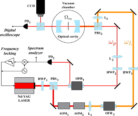
Figure 1. Schematic description of the experimental setup.
Download figure:
Standard imageThe cavity is L ≈ 93 mm long and consists of two equal dielectric mirrors, each with a radius of curvature R = 10 cm. The measured value of the empty cavity finesse is  and is consistent with the mirror's nominal reflectivity. Halfway between the mirrors a thin stoichiometric silicon nitride membrane is mounted on series of piezo-motor driven optical mounts that control the angular alignment as well as the linear positioning with respect to the optical axis.
The membrane is a commercial 1 mm × 1 mm Si3N4 stoichiometric x-ray window (Norcada) with nominal thickness Ld = 50 nm and index of refraction nR ≈ 2, supported on a 200 μm Si frame. It has been chosen due to its high mechanical quality factor and very low optical absorption at λ = 1 064 nm [33]. Its optical properties were also experimentally verified, yielding an intensity reflection coefficient of  and an imaginary part of the index of refraction nI ≈ 2 × 10⁻⁶.
The membrane's mechanical motion is monitored by the probe beam with frequency ωp that is also used for locking the laser to the FP instantaneous resonant frequency. This is done by polarization multiplexing of the fields on PBS2 and by observing only the probe light reflected from the cavity by a photodiode PD2, whose output signal is amplified and fed into a frequency locking loop and a spectrum analyzer where the membrane's mechanical motion is observed. The locking scheme is a standard Pound–Drever–Hall (PDH) scheme [34, 35], where the sidebands necessary for obtaining the error signal feeded into the locking loop are created by modulating directly the laser crystal [36]. Although the pump field is modulated as well, its sidebands are out of resonance and do not contribute to the optomechanical dynamics. In order to avoid the deterioration of the mechanical properties of the membrane and optical properties of the FP cavity, the cavity is mounted inside a vacuum chamber which is evacuated by a turbo-molecular pump down to 10−5 mbar. Once the base pressure is reached, the pump is switched off and disconnected from the vacuum chamber in order to minimize the mechanical noise. Due to some leaks, the residual pressure inside the chamber reaches values as high as 10−2 mbar in about 1 day. This has caused a worsening of the membrane's mechanical quality factor, which did not reach values of the order of 1 million, as instead reported in [33]. A vibrationless pumping scheme is being prepared for future measurements.
3. A quantum Langevin description
Radiation pressure of the intracavity field excites the membrane vibrational modes, and therefore one has a multimode bosonic system in which mechanical and optical modes interact in a nonlinear way. However, one can adopt a simplified description based on a single-cavity mode interacting with a single mechanical mode [26, 28, 29, 32]. One can restrict to a single-cavity mode if the driving laser populates a given cavity mode only (here a TEM00 mode, associated with the annihilation operator  ), and if scattering into other modes is negligible [37]. Moreover, one can consider a single mechanical mode of the membrane (described by dimensionless position
  and momentum
  operators, such that
 ![$[\hat {q},\hat {p}]= \mathrm {i}$](https://content.cld.iop.org/journals/1367-2630/14/9/095015/revision1/nj435607ieqn7.gif) ) when the detection bandwidth is chosen so that it includes only a single isolated mechanical resonance with frequency Ωm.
) when the detection bandwidth is chosen so that it includes only a single isolated mechanical resonance with frequency Ωm.
By explicitly including cavity driving by the pump laser with frequency ωL and input power  , the system Hamiltonian reads

where  , with κ0 the coupling rate through the input mirror. The optomechanical interaction is described by the position-dependent optical frequency

where ω0 is the cavity mode frequency in the absence of the membrane, and ![${\rm{Re}}\{\delta \omega [z_0(\hat {q})]\}$](https://content.cld.iop.org/journals/1367-2630/14/9/095015/revision1/nj435607ieqn10.gif) is the frequency shift caused by the insertion of the membrane. This shift depends on the membrane position along the cavity axis
is the frequency shift caused by the insertion of the membrane. This shift depends on the membrane position along the cavity axis  , which in turn depends on the coordinate
  , as one can see by writing
  , where z0 is the membrane center-of-mass position along the cavity axis, Θ is the transverse overlap integral between the optical mode and the vibrational mode [32], and
  , with m the effective mass of the mechanical mode. The parameter x0 is the natural unit length of the problem and corresponds to the width of the zero-point position fluctuations of the mechanical resonator multiplied by
  .
.
The system is, in general, affected by fluctuation–dissipation processes: the mechanical mode undergoes a viscous force with damping rate γm and a Brownian stochastic force with zero mean value  . We operate at room temperature T, and the correlation function of this Brownian noise is well approximated by the following [38–40]:

where kB is the Boltzmann constant, ![$n=[\exp (\hbar \Omega_{\mathrm {m}}/k_{\mathrm {B}}T)-1]^{-1} \approx k_{\mathrm{B}} T/\hbar \Omega _{\mathrm{m}}$](https://content.cld.iop.org/journals/1367-2630/14/9/095015/revision1/nj435607ieqn17.gif) is the mean thermal phonon number at temperature T and δ'(t − t') denotes the derivative of the Dirac delta.
is the mean thermal phonon number at temperature T and δ'(t − t') denotes the derivative of the Dirac delta.
The cavity mode loses photons through the input mirror with decay rate κ0, through the back mirror with decay rate κ2, and also due to optical absorption of the membrane with decay rate ![$\kappa _1(\hat {q})\equiv |{\rm{Im}}\{\delta \omega [z_0(\hat {q})]\}|$](https://content.cld.iop.org/journals/1367-2630/14/9/095015/revision1/nj435607ieqn18.gif) , which is nonzero owing to the small imaginary part of the refraction index, nI [32]. Optical absorption of the membrane depends on the mechanical position operator
, which is nonzero owing to the small imaginary part of the refraction index, nI [32]. Optical absorption of the membrane depends on the mechanical position operator  , and represents therefore a nonlinear dissipative process affecting both the optical and the mechanical modes. Each decay channel is associated with a vacuum optical input noise
  , j = 0,1,2, with correlation functions [39]

Adding the above damping and noise terms to the Heisenberg equations of motion derived from the Hamiltonian of equation (1), one obtains the following set of nonlinear quantum Langevin equations (QLE) that, in the frame rotating at the pump laser frequency ωL, read


where ∂q denotes the derivative with respect to  , and
, and  is the total cavity decay rate.
Equations (5)–(7) illustrate the peculiar aspects of the MIM scheme with respect to the paradigm optomechanical system represented by a FP cavity with a highly reflecting movable micro-mirror, which satisfactorily applies to a large number of optomechanical devices [41]. In the latter scheme,  and the optical absorption can be usually neglected [
 ], and therefore the nonlinearities in
  appearing in equations (5)–(7) are absent. Our experimental results will show that the quadratic term in the power expansion of
  has appreciable effects on the optically induced mechanical frequency shift. In contrast, we will see that membrane absorption can be neglected also in our case, due to the very low value of nI of the stoichiometric Si3N4 membrane employed here.
3.1. Linearized quantum Langevin equations
Our experiment is carried out in the usual 'linearized' regime characterized by an intense stationary intracavity field with amplitude αs (|αs| ≫ 1), easily achievable with moderate pump power due to the large cavity finesse  . The vibrational mode is correspondingly deformed, with a new stationary position qs, satisfying, together with αs, the coupled nonlinear conditions


which may show optical bistability [42–44].
When the system is stable, the relevant dynamics concern the fluctuations of the cavity and mechanical modes around the classical steady-state described by equations (8) and (9). Rewriting each Heisenberg operator of equations (5)–(7) as the classical steady-state value plus an additional fluctuation operator with zero mean value, and neglecting all the nonlinear terms in the equations, one obtains the following linearized QLE for the fluctuations [32]:


We have redefined the phase reference of the cavity field so that αs is real and positive, and we have defined the effective detuning Δ = ω(qs) − ωL and  . The linearized QLE (10)–(12) show that the mechanical and cavity mode fluctuations are coupled by the effective optomechanical coupling

which can be enhanced by increasing the intracavity amplitude αs. Furthermore, G can be fine tuned in the MIM system by shifting the membrane along the cavity axis, thereby changing ∂ω/∂z0.
4. Effect of radiation pressure on the membrane vibrational mode
We observe the motion of the vibrational mode by detecting the noise spectrum of the phase ϕ(ω) of the resonant weak probe field reflected by the cavity by means of the PDH technique. This phase is related to the effective position  by
by

where

is the effective optomechanical coupling of the resonant probe beam, analogous to the coupling of the driving field of equation (13), but with the corresponding input power  , coupling rate κp and overlap integral Θp. s(ω) denotes the detection noise, essentially given by shot noise, which at resonance is uncorrelated with
  , implying that the phase noise spectrum is given by

where Sq(ω) is the spectrum of the dimensionless position  , and Ss is the (typically flat) shot noise spectrum. After calibration in m2 Hz−1 (and using
  ), the detected spectrum can be written as

The explicit expression for Sq(ω) is obtained by solving the linearized QLE (10)–(12) in the frequency domain [14, 32, 45] and reads

where

is the thermal noise spectrum,

is the radiation–pressure noise spectrum due to the intense pump beam at frequency ωL, and

is the additional noise spectrum associated with membrane absorption [32]. It is worth noting that the position (phase) noise is dominated only by the intense pump field (G), and that the probe field (Gp) is only involved in the detection. The main effect of the optomechanical interaction on the membrane vibrational mode is the modification of its mechanical susceptibility (see equation (18)), which becomes

where

and  is the mechanical frequency modified by the second-order contribution to the expansion of
  .
.
This effective susceptibility can be read as the susceptibility of an oscillator with effective resonance frequency and damping rate, respectively, given by


The present experiment is carried out in the weak-coupling regime G ≪ Ωm, and consequently the effective susceptibility χeff(ω), even if appreciably modified, remains peaked approximately around Ωm. Therefore, the effective mechanical frequency and damping modified by the optomechanical interaction can be satisfactorily estimated by evaluating equations (24) and (25) at ω = Ωm.
The modification of the mechanical response due to the interaction with the driven cavity mode is clearly visible in figure 2, where the calibrated position spectrum is shown at different positive values of the detuning of the driving field Δ: the mechanical resonance peak shifts and broadens with varying Δ. We note that just outside the resonance peak, the displacement sensitivity of our optomechanical detection system is equal to  , where Sx,SQL(Ωm) = 2ℏQ/mΩ2m is the standard quantum limit (SQL) for a displacement spectral measurement at its peak value at resonance. This value is not far from the value
  recently achieved in a Michelson–Sagnac interferometer also based on a SiN membrane [46].
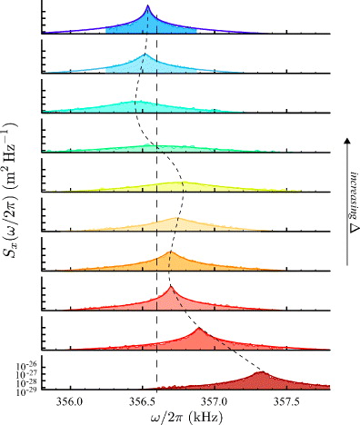
Figure 2. Calibrated position noise spectrum around the resonance associated with the fundamental vibrational mode of the membrane, with bare mechanical frequency Ωm/2π = 356.6 kHz, mass m = 45 ng, quality factor Q = 24 000, at different values of the detuning Δ/2π = (30, 60, 180, 280, 320, 340, 355, 380, 410, 600) kHz, from the lower to the upper curve. The membrane is fixed at 10 nm distance from a field node and the driving input power is  .
.
Download figure:
Standard imageWe have studied in detail the effective mechanical frequency Ωeffm and the effective mechanical damping γeffm as a function of the detuning Δ, which is shown in figures 3 and 4. Dots correspond to the experimental data obtained by a Lorentzian fit of the resonance peak of the detected spectrum, while the continuous red curves correspond to the theoretical prediction of equations (24) and (25) evaluated for the experimental parameter values Ωm/2π = 356.6 kHz, mass m = 45 ng, quality factor Q = 24 000, membrane distance from a field node z0 = 10 nm, overlap integral Θ ≈ 1, driving input power  and κL(qs) = 77 kHz. As expected, we see a significant increase of mechanical damping, and therefore cooling, at the resonant condition Δ = Ωm, which corresponds to the situation where the driving laser is resonant with the red sideband of the cavity. In this condition, the scattering of anti-Stokes (Stokes) photons into the cavity is enhanced (suppressed) [12–14] and the net laser cooling rate is maximum.

Figure 3. Scaled effective mechanical damping γeffm/γm versus the scaled cavity-driving detuning Δ/Ωm, in the region of positive detunings corresponding to a driving red-detuned with respect to the cavity mode. Dots are the experimentally measured values, while the red full line refers to the prediction of equation (25). See figure 2 and text for the other parameter values.
Download figure:
Standard image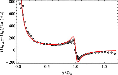
Figure 4. Mechanical frequency shift Ωeffm − Ωm versus the scaled cavity-driving detuning Δ/Ωm, in the region of positive detunings corresponding to a driving red detuned with respect to the cavity mode. Dots are the experimentally measured values and the red full line refers to the prediction of equation (24). The membrane is shifted by z0 = 10 nm along the cavity axis with respect to a field node. See figure 2 and text for the other parameter values.
Download figure:
Standard imageThe best-fit curve yields a negligible value for the membrane absorption-related parameter Γ, |Γ| ≲ 4 × 10⁻⁸Ωm, which is consistent with the value nI ≈ 2 × 10⁻⁶ estimated in [47] and reasonable for stoichiometric Si3N4 membranes [29]. The best-fit curve also yields a small, but non-negligible, value for the parameter h related to the mechanical frequency shift caused by the second-order term of the expansion of the position-dependent cavity frequency  , h = 10−5Ωm (around Δ = Ωm).
This fact suggests that it should be possible to observe directly the frequency shift caused by the nonzero second-order derivative ∂2ω/∂z20, which is absent in FP cavities with a vibrating micromirror. Equation (24) suggests that such an effect should be visible around optical resonance Δ ≈ 0, where the frequency shift caused by the radiation–pressure interaction (the second fractional term in equation (24)) is negligible. This is confirmed by the data shown in figure 5, where the mechanical frequency shift Ωeffm − Ωm is plotted for a membrane position z0 ranging between a node and an antinode of the cavity field. Black dots are the experimental data, and the red full line refers to the theoretical prediction of equation (24) with the same parameters as figure 2 except that  and Δ = 0. It is evident that the second-order correction, even though small, is appreciable and that including the quadratic term in the dependence of the cavity frequency on the membrane deformation
  is necessary for a proper description of the experimental results. The experimental data depart from the theory prediction in a narrow z0 interval due to the presence of an avoided crossing between the driven TEM00 mode and a higher-order mode, which is responsible for an appreciable modification of the optomechanical coupling G [44, 48].
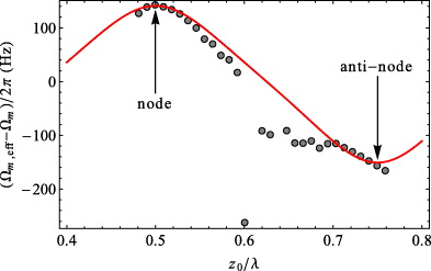
Figure 5. Mechanical frequency shift Ωeffm − Ωm versus the membrane position along the cavity axis, from a node to an antinode of the cavity field, at the optical resonance Δ = 0. Dots refer to the measured values and the continuous red line refers to the prediction of equation (24). The other parameter values are the same as in figure 2 except that  . The oscillatory behavior and the change of sign of the frequency shift are due to the similar behavior of the second-order derivative (see equation (23)). The narrow interval where the data depart from theory prediction corresponds to the presence of an avoided crossing between the driven TEM00 mode and a higher-order transverse mode (see also text).
Download figure:
Standard imageMeasuring the position spectrum allows us to deduce also the effective mean thermal phonon number neff, i.e. the effective temperature Teff, of the vibrational mode, as one can see from the general relation [12–15]

where the position and momentum variances can be expressed in terms of the noise spectrum Sq(ω) as

However, as shown in [14, 15], energy equipartition  holds in a large parameter regime implying that

where the latter definition can be applied far from the quantum regime (neff ≈ 1), pertaining to our experimental situation. Therefore, Teff can be obtained evaluating the area below the mechanical resonance peak after subtraction of the flat noise floor due to detection noise (see equation (17)).
There are two further ways of inferring Teff from the measured position noise spectrum. On the one hand, Teff can be deduced from γeffm/γm of figure 3: from a thermodynamical point of view, due to radiation–pressure cooling, the vibrational mode passes from a thermal environment characterized by a Langevin force with strength proportional to γmT to an effective one with a Langevin force of the same strength, which is however proportional to γeffmTeff, so that [49, 50]

On the other hand, one can use the height of the resonant peak of the calibrated spectrum Sx(ω). The extremely small value of Γ, and the fact that our experiment is carried out at room temperature T = 295 K and in the weak-coupling limit (G ≈ −0.01Ωm at Δ = Ωm in figures 3 and 4), implies that both the radiation–pressure contribution Srp(ω) and the absorption contribution Sabs(ω) are negligible with respect to that of thermal noise. Therefore one can safely assume that

Using the fact that at resonance ω = Ωeffm, the mechanical susceptibility becomes  , and recalling that γmT = γmeffTeff, equation (30) yields

providing the definition of a 'peak' temperature Tpeff.
The three different estimates for the effective vibrational mode temperature, Tγeff, Tpeff, and the one associated with equation (28), Tareaeff, are plotted in figure 6 versus the scaled cavity-driving detuning Δ/Ωm, for the same set of parameters of figures 2–4. The three different sets of temperature values agree with each other and with the theoretical prediction. A subset of these data around the resonant condition Δ/Ωm = 1 is then compared with the corresponding data with a larger optomechanical coupling in figure 7. The upper curve refers to the small coupling regime of figure 6, while the lower curve, showing better cooling, is obtained in a different experimental condition, with the membrane at 15 nm distance from a field node (larger ∂ω/∂z0) and a driving input power  , which corresponds to the larger coupling G ≈ −0.031Ωm (at Δ = Ωm). In the second case, the vibrational mode is cooled down by a factor of ≈350. Moreover, the three different estimates of the effective temperature are again consistent between them and with the theoretical prediction (full line in figure 7).

Figure 6. The figure shows the three different estimates of the vibrational mode temperature, Tγeff, Tpeff and Tareaeff versus the scaled cavity-driving detuning Δ/Ωm. The parameters of the fitting curve are as in figure 2. Circles correspond to Tγeff, diamonds to Tpeff, and squares to Tareaeff.
Download figure:
Standard image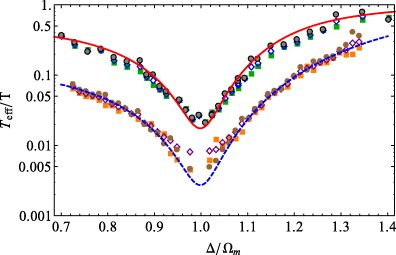
Figure 7. The figure shows the three different estimates of the vibrational mode temperature, Tγeff, Tpeff and Tareaeff versus the scaled cavity-driving detuning Δ/Ωm, around resonance with the red sideband of the cavity mode frequency, Δ/Ωm = 1. The upper curve refers to the small coupling regime of figure 2, while the lower curve refers to a different situation with larger coupling (G ≈ −0.031Ωm at Δ = Ωm), obtained with the membrane at 15 nm distance from a field node, and larger driving input power  . Circles correspond to Tγeff, diamonds to Tpeff and squares to Tareaeff.
Download figure:
Standard image5. Concluding remarks
We have performed an experimental study of the optomechanical device formed by a vibrating 50 nm thick Si3N4 membrane placed within a high-finesse optical FP cavity at room temperature. We have studied in particular how the radiation–pressure interaction with the driven cavity mode modifies the mechanical susceptibility of the vibrational mode due to the back-action of the detuned optical field. The measured mechanical frequency shift and the modified mechanical damping as a function of detuning and optomechanical coupling are well reproduced by a Langevin equation description of the system [32]. The increase of damping is equivalent to cooling the vibrational mode, and we demonstrate a decrease of the effective temperature by a factor of ≈350. We also observe a mechanical frequency shift which is not associated with the standard optical spring effect, but that can be explained only taking into account the quadratic term in the parametric dependence of the cavity frequency on the effective membrane position. This second-order term, which is usually negligible in most optomechanical devices, cannot be neglected in a proper description of the present MIM setup.
Acknowledgment
This work has been supported by the European Commission (FP-7 FET-Open project MINOS).