


Abstract
Magnesium–yttrium alloys show significantly improved room temperature ductility when compared with pure Mg. We study this interesting phenomenon theoretically at the atomic scale employing quantum-mechanical (so-called ab initio) and atomistic modeling methods. Specifically, we have calculated generalized stacking fault energies for five slip systems in both elemental magnesium (Mg) and Mg–Y alloys using (i) density functional theory and (ii) a set of embedded-atom-method (EAM) potentials. These calculations predict that the addition of yttrium results in a reduction in the unstable stacking fault energy of basal slip systems. Specifically in the case of an I2 stacking fault, the predicted reduction of the stacking fault energy due to Y atoms was verified by experimental measurements. We find a similar reduction for the stable stacking fault energy of the  non-basal slip system. On the other hand, other energies along this particular γ-surface profile increase with the addition of Y. In parallel to our quantum-mechanical calculations, we have also developed a new EAM Mg–Y potential and thoroughly tested its performance. The comparison of quantum-mechanical and atomistic results indicates that the new potential is suitable for future large-scale atomistic simulations.
Export citation and abstract BibTeX RIS

Content from this work may be used under the terms of the Creative Commons Attribution 3.0 licence. Any further distribution of this work must maintain attribution to the author(s) and the title of the work, journal citation and DOI.
1. Introduction
Magnesium alloys are promising candidate materials for lightweight industrial applications [1, 2]. Unfortunately, a wider use of magnesium and many Mg-based alloys is impeded by their poor room-temperature ductility, which is caused by basal-type texturing and limited available deformation mechanisms. It is known [3] that addition of Y and/or rare-earth elements increases the ductility by texture weakening and higher activity of non-basal slip systems. Specifically, shear deformations with a component along the 〈0001〉 axis, including twinning and 〈c + a〉 slip systems, were shown (e.g. in [4]) to determine the mechanical behavior of hcp metals (figure 1). The limitation to mainly basal 〈a〉 slip and tensile twinning in pure Mg and most commercial wrought Mg alloys causes strain localization in a few shear bands and early fracture of the materials along these shear bands. It has been shown experimentally [5] that alloying Y leads to higher activation of non-basal deformation modes, i.e. non-basal dislocation slip and compression twinning, and consequently to much enhanced ductility at room temperature. Nucleation and mobility energies of dislocations, both perfect and dissociated dislocations, are related to the stable and unstable stacking fault energies which are available via atomistic calculations.

Figure 1. Schematic drawing showing possible slip systems in hcp metals. Specifically the (0001)[01–10] is considered here for studying the I2 stacking fault.
Download figure:
Standard imageDifferent slip mechanisms in Mg have been intensively studied both experimentally [5–8] and theoretically [4, 9–11]. Theoretical studies generally focused on calculating so-called generalized stacking fault energy (GSFE) profiles obtained by sliding one half of a crystal over the second half across a given glide plane. As shown by Vitek [12], these energy profiles are closely connected with the motion of dislocations and the plasticity of materials in general. GSFEs of important planes along different slip directions were calculated employing both density functional theory (DFT) and the embedded atom method (EAM) for pure Mg [13–17]. It was shown, for example, that maxima occurring along GSFE profiles, so-called unstable stacking fault energies (USFEs), determine the behavior of slip modes and thus the ductility in fcc metals [18].
Our study is motivated by the fact that rather little is known about GSFEs in Mg–Y alloys, especially in the case of non-basal deformation modes (see e.g. table 1). Therefore, we study and compare the influence of Y additions on the behavior of both basal and non-basal slip systems. Our aim was to provide results that will contribute to the understanding of enhanced room temperature ductility of Mg–Y alloys [5] and to the design of ductile Mg-based materials in the future.
Table 1. Independent deformation modes in hcp crystals.
| Slip systems | Direction | Plane | Independent deformation modes |
|---|---|---|---|
 |
〈a〉 | Basal | 2 |
 |
〈a〉 | Prismatic | 2 |
 |
〈a〉 | Pyramidal | 4 |
| {hki0}〈0001〉 | 〈c〉 | Prismatic | – |
 |
〈a+c〉 | Pyramidal | 5 |
Due to the fact that it is experimentally very difficult to obtain a deeper insight into various mechanisms that are simultaneously active in Mg alloys at atomic scale, we employ theoretical methods as these allow for decomposing this complexity into individual processes and studying them separately. Unfortunately, even theoretical modeling is limited by available computer resources, especially in the case of state-of-the-art quantum-mechanical calculations. The predictive power and reliability of these calculations can nowadays be applied only to problems involving a few hundreds of atoms. As processes related to the plasticity of materials typically span over much larger scales, methods based on inter-atomic potentials are often used instead. For these simulations, well-tested and reliable potentials are necessary. Therefore, we have not only employed quantum-mechanical calculations but, in a complementary manner, we have also developed a new Mg–Y EAM potential. We first carefully validated our potential and only after this then used it to simulate processes involving so many atoms that quantum-mechanical calculations would be prohibitively long. In order to verify our theoretical predictions, an experimental TEM analysis of the I2 stacking fault was performed and confirmed our theoretical findings.
2. Methodology
2.1. γ-surface simulations
Employing theoretical methods, slip deformation modes can be studied by calculating generalized stacking fault energies, known as γ-surfaces [12]. Key properties of slip deformation modes such as the Peierls barrier as well as stacking fault energies can be deduced from the γ-surfaces. We determine the generalized stacking fault energies by incrementally shifting the upper half crystal along the slip direction and calculating the total energy of the system as a function of the applied shift vector. In order to facilitate the consideration of a single stacking fault, and so allow us to reduce the required system dimensions, we added the applied shift vector to the lattice vector along the glide plane normal (in our case the glide plane normal is denoted as the z-direction). For the minimization after each incremental shift, atomic positions are constrained along the lateral dimensions of the glide plane, but atoms can reduce the total energy of the system by relaxing in the direction perpendicular to the studied glide plane.
In order to eliminate any spurious interactions between the interface (i.e. the glide plane) and its periodic images, the supercell size must be sufficiently large. We therefore converged the GSFE with respect to the number of atomic planes parallel to the fault plane. For example, in order to determine an optimum number of atomic planes for the  slip system, supercells with 2, 4, 6, 8 and 12 layers along the
  direction, the z-direction (parallel to the plane normal), were used to calculate GSFEs. The GSFE difference between 6-layer (2 × 2 × 6, 24 atoms) and 12-layer (2 × 2 × 12, 48 atoms) supercells is less than 1%. Therefore, supercells with more than six layers are considered large enough. In our case, a 48-atom supercell was employed to obtain a realistically low Y concentration. Converged supercell sizes of all the other slip systems considered were determined similarly (see table 2). In calculations of Mg–Y alloys, one Mg atom is replaced by a Y atom on the first plane (with the smallest value of the z-axis in the coordinate system). Therefore, in Mg55Y the concentration of Y is 1.82 at.% and 2.08 at.% for Mg47Y in all the other considered slip systems.
Table 2. Different stoichiometries with corresponding supercell sizes and slip systems in EAM calculations.
| Slip systems | Supercell size | No. of atoms |
|---|---|---|
 |
2×2×6 | 48 |
 |
2×2×7 | 56 |
 |
4×4×6 | 192 |
 |
4×4×3 | 192 |
 |
12×6×2 | 1728 |
In the case of the γ-surface for the  plane, two perpendicular vectors (
![$\frac {1}{3}[11\bar {2}3]$](https://content.cld.iop.org/journals/1367-2630/15/4/043020/revision1/nj459874ieqn14.gif) and
and ![$[10\bar {1}0]$](https://content.cld.iop.org/journals/1367-2630/15/4/043020/revision1/nj459874ieqn15.gif) ) are selected on the plane. All displacements in the slip plane can be obtained by a combination of these two vectors. Suppose x and y are fractional displacements along the two directions; the GSF vector
) are selected on the plane. All displacements in the slip plane can be obtained by a combination of these two vectors. Suppose x and y are fractional displacements along the two directions; the GSF vector  may be written as
 ![$ \skew3\vec{f} = x\frac {1}{3}[11\bar {2}3] + y~[10\bar {1}0],$](https://content.cld.iop.org/journals/1367-2630/15/4/043020/revision1/nj459874ieqn17.gif) where 0 ⩽ x ⩽ 1 and 0 ⩽ y ⩽ 1. More details about the calculation of the γ-surface can be found in [19].
where 0 ⩽ x ⩽ 1 and 0 ⩽ y ⩽ 1. More details about the calculation of the γ-surface can be found in [19].
2.2. Parameters of ab initio calculations
In our work, we calculate GSFE profiles using both DFT [20, 21] and the EAM [22] (using the LAMMPS [23] package.). Our DFT calculations were carried out using the projector augmented wave method [39] and the electronic exchange–correlation effects were described by the generalized gradient approximation [40] as implemented in the Vienna Ab initio Simulation Package (VASP) [41, 42]. A plane wave energy cut-off of 350 eV is used for both pure Mg and the Mg–Y alloys. The Brillouin zone was sampled using dense Monkhorst–Pack [43] k-point meshes that were chosen to ensure a convergence of the total energy to within 1 meV per atom. Atomic relaxations were performed until the energy and forces converged to 10−7 eV and 10−3 eV Å−1, respectively. To test our computational parameters, we have calculated the lattice parameters of pure Mg. The results, a = 3.1886 Å and c/a = 1.6261 (table 3), are in good agreement with experimental data suggesting a = 3.21 Å and c/a = 1.624 [44].
Table 3. DFT-computed lattice parameters for pure Mg and Mg–Y alloys with different stoichiometries with corresponding supercell sizes and slip systems.
| Stoichiometry | a (Å) | c/a | Supercell size | Atom no. | Slip systems |
|---|---|---|---|---|---|
| Mg | 3.1886 | 1.6261 | 2×2×2 | 16 | All slip systems |
| Mg55Y | 3.2004 | 1.6253 | 2×2×14 | 56 |  |
| Mg47Y | 3.2064 | 1.6215 | 2×2×12 | 48 |  , ,  , ,  , ,  |
2.3. Development of Mg–Y embedded atom method potential
Empirical potentials provide a means of exploring the physics of systems of atoms on length- and time-scales currently inaccessible to more computationally expensive ab initio techniques. Such potentials seek to approximate the energy of a system of atoms, and the forces between those atoms, as a classical function of the relative positions of the atoms treated as point particles. The key attributes of such potentials are: (i) the level of physics they aim to capture, i.e. whether they are simple pair potentials or attempt to capture many-atom effects and whether they are functions only of atomic separations or also of bond angles; (ii) the nature of the functions used in the fitted potential, which is to say, the extent to which those functions have a (perhaps physically motivated) prescribed form versus being, say, piecewise spline fitted; and (iii) the data to which those functions are fitted, which may be energies and elastic properties from experiment and ab initio calculations or individual atomic forces from ab initio calculations for a set of atomic configurations. The key issue for empirical potentials, especially when they are to be used to explore systems beyond the reach of ab initio, is their transferability: it is one thing to correctly reproduce the properties to which a potential is fitted and quite another to provide accurate predictions of 'unseen' data. As no existing potential (e.g. [45]) has been developed specifically for GSFE calculations, we provide a new one.
In this study, an EAM interatomic potential was developed to describe the Mg–Y system, which has the following formalism [22, 24]: Etot = Σi,jϕ(rij) + ΣiF(ni), where n = Σjρ(rij) and ϕ(r), ρ(r) and F(ni) are the pair, density and embedding functions. In this work, the three functions ϕ(r), ρ(r) and F(ni) are represented with quintic spine interpolations [25]. We used 15 equidistant spline knots for both the pair and the density functions (in the fitting range of 0.5–6.5 Å), and 6 spline knots for the embedding function. For the Mg–Y binary system, a total number of 83 parameters was fitted.
The EAM potential was developed based on the force-matching method [25, 26] as implemented in the POTFIT package [27]. To this end, a first-principles database was first established to provide a coarse-grained potential energy surface (PES) of the Mg–Y system. The database was constructed to encompass a wide range of atomic configurations, including all crystalline phases in this alloy system, as well as their derivative structures such as defects, crystal equations of state, deformation paths, melting and cooling trajectories, etc. In addition to six crystal structures of Mg and Y (i.e. hcp, bcc, fcc, 9R, diamond and sc structures), three crystallographic types of Mg–Y intermetallic compounds [28] are considered in this work, including Mg24Y5 ( ), Mg2Y (P63/mmc) and MgY (Pm3m).
Ab initio molecular dynamics (MD) simulation [29] was conducted to obtain liquid structures as well as their trajectories along the heating and cooling processes. Altogether, around 700 configurations (with each configuration typically containing 100 atoms) were selected and subjected to DFT calculations using the pseudopotential and plane-wave method implemented in the VASP [41, 42]. The derived PES (the potential energy and stress tensors of each configuration, forces on each atom and elastic constants of two reference structures) was further modified to match the experimental values of the lattice parameter and cohesive energy of Mg and Y, and was then utilized to parameterize the EAM potential for the Mg–Y system. A similar practice can be found in [25]. During potential fitting, ad hoc EAM potentials were employed in classical MD to probe deeper potential basins on the PES, with new configurations added to the previously built potential database for a new round of EAM parameterization. Several iterations were performed until self-consistency between ab initio and EAM calculations was reached.
To demonstrate the overall performance of the as-developed EAM potential, we compare the present EAM model with previous models for Mg and Y in terms of the accuracy of predicting a set of material properties, as shown in tables 4 and 5. The performance of the EAM potential for Mg–Y alloys can be seen from figure 2, where the equations of state of the crystalline phases derived from the EAM model and the ab initio treatment are provided. The cohesive energies of the intermetallic compounds, with tabulated lattice parameters, are listed in table 6 for comparison. The general agreement between EAM and ab initio calculations is satisfactory. The as-developed EAM potential is available from https://sites.google.com/site/eampotentials/Home/MgY.

Figure 2. Comparison of ab initio and EAM calculations of the cohesive energies of Mg–Y alloys at different volumes.
Download figure:
Standard imageTable 4. Physical properties of Mg predicted by the present EAM model and other EAM models. Ec is the cohesive energy, Efν is the relaxed vacancy formation energy, Emν is the migration energy of the vacancy.
| Experiment/theory | Present model | Suna | Liub | |
|---|---|---|---|---|
| a (Å) | 3.21c | 3.21 (300 K) | 3.206 | 3.206 |
| c/a ratio | 1.623c | 1.610 | 1.623 | 1.623 |
| Ec (eV atom−1) | 1.510d | 1.510 | 1.516 | 1.516 |
| C11 (GPa) | 59.5e | 59.5 | 69.6 | 61.8 |
| C12 (GPa) | 26.1e | 25.7 | 25.3 | 25.9 |
| C13 (GPa) | 21.8e | 20.9 | 16 | 21.9 |
| C33 (GPa) | 61.6e | 62.7 | 69.5 | 67.5 |
| C44 (GPa) | 16.4e | 15.8 | 12.8 | 18.2 |
| Efν (eV) | 0.59 ≈0.89b | 0.62 | 0.88 | 0.87 |
| Emν (eV) | 0.39b | 0.47 | 0.64 | |
| Esurface (mJ m−2) | 680f | 480g | 495 | |
| Efcc−hcp (eV) | 0.011b, 0.007h | 0.006 | 0.012 | 0.015 |
| Ebcc−hcp (eV) | 0.028b | 0.024 | 0.014 | 0.018 |
| Tm (K) (hcp) | 923i | 850 |
aSun et al [30]. bLiu et al [31]. cBarrett and Massalski [34]. dKittel [35]. eSimons and Wang [36]. fde Boer [37] gAverage of basal plane and prism plane surface energies. hFirst-principles results as a part of this work. iCampbell [38].
Table 5. Physical properties of Y predicted by the present EAM model and other EAM models. Ec is the cohesive energy, Efν is the relaxed vacancy formation energy, Emν is the migration energy of the vacancy.
| Experiment/theory | Present model | Hua | Baskesb | |
|---|---|---|---|---|
| a (Å) | 3.65c | 3.65 (300 K) | 3.65 | 3.65 |
| c/a ratio | 1.57c | 1.57 | 1.57 | 1.57 |
| Ec (eV atom−1) | 4.37d | 4.37 | 4.37 | |
| C11 (GPa) | 77.9e | 78.3 | ||
| C12 (GPa) | 28.5e | 26.8 | ||
| C13 (GPa) | 21.0e | 21.9 | ||
| C33 (GPa) | 76.9e | 77.2 | ||
| C44 (GPa) | 24.3e | 21.7 | ||
| Efν (eV) | 1.50f | 1.70 | 1.22 | 1.25 |
| Emν (eV) | 0.66 | 0.59 | ||
| Esurface (mJ m−2) | 1125g | 830 | 868 | 625 |
| Efcc−hcp (eV) | −0.03 | |||
| Ebcc−hcp (eV) | 0.022g | 0.020 | ||
| Tm (K) (hcp) | 1796h | 1810 |
aHu et al [32]. bBaskes and Johnson [33]. cBarrett and Massalski [34]. dKittel [35]. eSimons and Wang [36]. fBoer et al [37]. gFirst-principles results as a part of this work. hCampbell [38].
Table 6. Cohesive energies of Mg–Y intermetallic compounds predicted by EAM and ab initio calculations. The lattice parameters are taken from [28].
| Compound | Lattice parameter | Cohesive energy ab initio (eV atom−1) | Cohesive energy EAM (eV atom−1) |
|---|---|---|---|
| MgY (Pm3m) | a=3.790 Å | 3.06 | 3.05 |
| Mg2Y (P63/mmc) | a=6.037 Å | 2.55 | 2.64 |
| c=752 Å | |||
Mg24Y5 ( ) ) |
a=3.790 Å | 2.05 | 2.07 |
3. Results and discussion
Our quantum-mechanical and atomistic calculations of GSFE profiles include five slip systems for both pure Mg and Mg–Y. Specifically, we consider the three 〈a〉-type slip systems ( ,
,  and
and  ), and the second pyramidal slip system (
 ), which contributes to shear deformation out of the basal plane, as well as the
  slip system, which is related to the intrinsic stacking fault I2 (I2 SF). The I2 stacking fault is formed when the [0001]-vector is altered by addition of
  . If we assign letters A, B and C to three possible stacking configurations of (0001) planes (in analogy to the stacking order of (111) planes in face-centered cubic lattices), the normal alternating hcp-stacking (... ABABABAB ...) is locally changed to an (... ABABCACA ...) stacking. Thus the influence of Y on the energetics of the I2 stacking fault can be studied by GSFE calculations. This part of our study represents a continuation of our previous experimental and theoretical study on the intrinsic stacking fault, I1 (see [46] for details).
3.1. Basal-plane generalized stacking fault calculations
3.1.1. Basal-plane slip systems
The computed GSFEs of {0001} along  are plotted as a function of the shift vector for pure Mg and the Mg–Y alloy in figure 3. The USFEs based on DFT calculations for pure Mg and the Mg–Y alloy (Mg47Y, 2.08 at.% Y) are 0.276 and 0.214 J m−2, respectively. The USFEs are thus predicted to be reduced by 22.5% due to the addition of Y. This finding is in agreement with previous DFT results [13] (0.288 J m−2 in Mg is reduced to 0.248 J m−2 in Mg–Y alloys). When studying the same GSFE employing atomistic EAM potentials, the trend is qualitatively the same but the reduction (from 0.233 J m−2 in Mg to 0.190 J m−2 in Mg47Y) is slightly smaller, 18.5%. The GSFE curves obtained by DFT and EAM calculations are similar with variations in the USFE ranging between 12% and 15% for Mg and the Mg–Y alloy. We can therefore conclude that both methods consistently predict the GSFE barriers to be reduced upon Y additions.
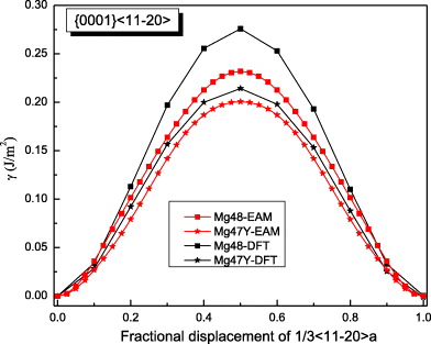
Figure 3. GSFE profiles calculated for Mg and Mg–Y alloys as a function of crystal displacement along the  direction in the basal plane. The total displacement (corresponding to 1.0 at the horizontal axis in the figure) is the respective lattice parameter a of either elemental Mg or the Mg47Y alloy. The unstable stacking fault corresponds to the displacement of 0.5a.
Download figure:
Standard image3.1.2. Prismatic  slip system

The GSFE curves of the prismatic 〈a〉 slip system  for pure Mg and the Mg–Y alloy (Mg55Y, 1.82 at.% Y) are shown in figure 4. In the four GSFE curves, there is only one global maximum corresponding to the unstable stacking fault energy (USFE) of the studied slip system. Based on our DFT calculations, the USFE is 44% lower in the Mg–Y alloy (0.128 J m−2) than in pure Mg (0.231 J m−2). The latter value for elemental Mg is in good agreement with previous DFT studies for pure Mg that reported 0.218 J m−2 [16] and 0.225 J m−2 [17]. The corresponding EAM results are qualitatively very similar but the predicted reduction is lower. Therefore, despite the fact that the actual energy barriers obtained by DFT and EAM calculations differ, the changes induced by Y alloying are qualitatively very similar and thus independent of our selected computational method.

Figure 4. Same as in figure 3 but for the  direction in the prismatic plane. The total displacement is equal to the corresponding lattice parameter a of either pure Mg or Mg–Y alloy (Mg55Y).
Download figure:
Standard image3.1.3. Pyramidal slip system

The GSFE results computed for the  pyramidal slip system are visualized in figure 5. The GSFE curves of the Mg–Y alloy calculated by DFT and EAM methods match very well. As in the case of the
  and
and  slip systems, the GSFEs predicted for pure Mg differ slightly. However, irrespective of the computational method used, GSFE values are lower in Mg–Y than those determined for pure Mg. Hence the DFT-calculated USFEs in Mg–Y alloys are reduced by 9% (from 0.343 J m−2 calculated for pure Mg). The corresponding EAM values indicate a reduction by 4% (from 0.323 J m−2 in pure Mg). The DFT-based USFE of pure Mg is in very good agreement with previous DFT results [14, 17].


Download figure:
Standard image3.1.4. The slip system

The computed GSFE curves for the  slip system of pure Mg and Mg47Y (2.08 at.%) are plotted as a function of the applied shift vector in figure 6. The four curves show similar characteristics, e.g. a local minimum corresponding to the displacement of ≈
  and a global maximum at a shift of about
  of the perfect lattice vector. The local minimum corresponds to the local stacking configuration (...ABABCACACA ...), which is the I2 SFE. The I2 SFEs in pure Mg and Mg47Y calculated by DFT are 0.037 and 0.030 J m−2, respectively, and so they exhibit a reduction by 0.007 J m−2 due to the Y atoms. The EAM values differ slightly but are qualitatively similar, with an I2 SFE of 0.017 J m−2 (in pure Mg) being reduced by 0.009 to 0.008 J m−2 (in the Mg47Y alloy).

Figure 6. Same as in figures 3–5 but along the  direction in the basal plane. The total displacement is
  , with a being the lattice parameter of either pure Mg or Mg–Y alloy (Mg47Y). The stable stacking fault energy and that of the unstable one correspond to displacements
  and
and  , respectively.
Download figure:
Standard imageThe global maximum of these GSFE curves corresponds to the stacking fault (...ABABABBCBCBC ...), which is characterized by the on-top position of the two atomic planes across the fault plane. The energy of this configuration in Mg and the Mg–Y alloy was found to be 0.475 and 0.445 J m−2, respectively, using DFT. The EAM calculated energies of these maxima are 0.444 and 0.413 J m−2, respectively, closely matching the corresponding Y-induced reduction in the USF energy predicted by DFT. Here we can conclude that irrespective of the material system (Mg or Mg–Y alloys), the GSFEs calculated by the EAM are apparently lower than those obtained using DFT. However, the trend of a Y-induced reduction in the GSFE is the same. The DFT-calculated energies of local GSFE maxima and minima (I2 SFE) are in quantitative agreement with previous results [13, 16, 17].
In order to verify this theoretical prediction that Y additions lower the I2 stacking fault, an experimental TEM study has been performed (for details related to TEM measurements, see our previous paper [5]). These TEM observations on slightly pre-deformed (1.5%) pure Mg and Mg–3Y (wt.%) were performed to measure the I2 SFE. In pure Mg no I2 stacking faults were observed, which indicates a relatively high stacking fault energy, i.e. a low probability to form these stacking faults or a dissociation width that is too small to be measured using conventional TEM. In Mg–3Y, frequent formation of the I2 stacking fault was observed allowing the measurement of the I2 SFE, figure 7. Here, the Burgers vectors (b) of the bounding partial dislocations of the stacking faults were determined according to the g·b invisibility criterion, figure 7. Both bounding partial dislocations are invisible under g = (0002), only one is visible under  and both are visible under
  , (
, ( ), (
), ( ) and (
 ), figure 7. Therefore, it is concluded that one partial dislocation has the Burgers vector
  ] and the other has the Burgers vector
 ![${\bf b} = 1/3 \ [01\bar {1}0]$](https://content.cld.iop.org/journals/1367-2630/15/4/043020/revision1/nj459874ieqn55.gif) building an I2 stacking fault according to the dissociation reaction: 1/3
building an I2 stacking fault according to the dissociation reaction: 1/3 ![$[11\bar {1}0] \rightarrow 1/3 \ [10\bar {1}0] + 1/3$](https://content.cld.iop.org/journals/1367-2630/15/4/043020/revision1/nj459874ieqn56.gif) [
[  ]. The corresponding stacking fault energies are calculated based on the dissociation width of the partial dislocations according to equation
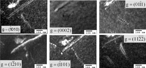
Figure 7. Weak-beam dark field TEM micrographs of an I2 stacking fault under different two-beam conditions. From the visibility of the bounding partial dislocations under the different diffraction conditions, their Burgers vectors were determined: b = 1/3 [  ] and b = 1/3 [
  ].
].
Download figure:
Standard imageHere, γ is the stacking fault energy, G the shear modulus, ν the Poisson's ratio, b the Burgers vector of the partials, β the angle between the partials and d the splitting width of the partials. Consequently, the I2 stacking fault energy of Mg–Y amounts to 1.5 ± 0.5 mJ m−2 with an average dissociation width of about 20–30 nm.
3.2. Non-basal plane generalized stacking fault energies
As the  slip system is an important non-basal slip system, its GSFE was also studied. The GSFE profiles of the slip system are calculated for pure Mg and Mg47Y (2.08 at.%) using both DFT and EAM calculations (see figure 8). The GSFE curves share similar shapes, with two maxima (one local and one global) and a local minimum along the shift vector. The local minimum corresponds to a stable stacking fault energy. The stable stacking fault energy predicted for Mg47Y by DFT (0.293 J m−2) is lower than that in pure Mg (0.318 J m−2). The EAM results suggest a smaller reduction in the stable SFE of only 0.008 J m−2 by the addition of Y. The energy difference corresponding to this reduction in the stable SFE is, however, very small and, in fact, quite close to the error bar of our EAM calculations.
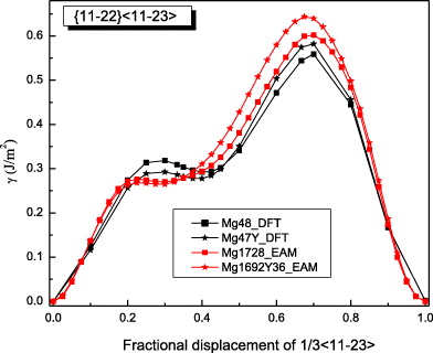
Figure 8. GSFE profiles calculated for the elemental Mg and Mg alloys as a function of the shifted displacement along the  direction in the non-basal plane
  . The total displacement is the length of the Burgers vector
  . The stable stacking fault energies, local unstable ones and global unstable ones correspond to crystal displacements of about 0.4, 0.25 and 0.7 calculated by DFT, and about 0.3, 0.22 and 0.7, respectively, by EAM.
Download figure:
Standard imageThe maximum of the GSFE (USFE) calculated by both DFT and EAM is higher in Mg47Y than in pure Mg. The DFT results are again very close to previous DFT results [14]. Both DFT and EAM data clearly indicate that the computed energies for Mg and Mg–Y crystals reverse their mutual order with increasing displacement (see figure 8). Specifically, the generalized stacking fault energies are first nearly equal for both Mg and Mg47Y for displacements lower than 0.2, then Y additions result in a clear lowering of stacking fault energies up to a displacement when GSFE curves of Mg and Mg47Y systems cross and the energies are beyond this point in the system containing the Y atoms. The displacement corresponding to the crossing point is ≈0.48 and 0.37 in the case of DFT and EAM results, respectively.
With regard to the local minima and maxima individual, the corresponding fractional displacements are not exactly equal when calculated by DFT and EAM methods. The DFT-calculated shallow minima (0.020 J m−2 for Mg and 0.015 J m−2 for Mg47Y) indicate a dissociation of the perfect  dislocation family into partial dislocations according to the following reaction:

where λ is a constant coefficient for the dissociation reaction. For λ = 0.4, the rows of atoms in the adjacent two gliding planes seem to be more regular than in any other case (see [19], figure 7, 0.6〈c + a〉).
A dissociation of perfect 〈c + a〉 dislocations was also found by other authors, but with different λ values. In [14], based on DFT and EAM (Liu potential), values of λ = 0.33 and 0.25, respectively, were found for pure Mg. In [19], a λ value of 0.5 was reported using an EAM potential taking in-plane relaxations of the atoms into account. The different λ values are due to the different calculation methods and the specific conditions. Lower SFE and USFE values indicate a tendency toward deformation mechanisms including partial dislocations when compared with pure Mg.
Despite a few discrepancies between DFT and EAM results, it can be concluded that, from a qualitative point of view, the EAM gives a rather accurate description of the GSFE in the  glide system. In particular, the trend that alloying Y in Mg reduces stable stacking fault energies is correctly captured. Further details related to the
  stable stacking faults will be described in the next subsection.
The calculated results obtained for the five studied slip systems are summarized in table 7 together with published data. The maxima along the GSFE profiles corresponding to the three basal slip systems indicate that the highest unstable stacking fault energy is expected for  dislocations on the pyramidal plane and the lowest on the prismatic plane. The ratios between the stable and unstable stacking fault energies are calculated for the
  and
and  slip systems. The actual results are listed in table 7. Moreover, table 7 reveals that the ratio between the stable and unstable stacking fault energies decreases in the
  slip system upon alloying with Y, further supporting the conclusion that Y alloying lowers the SFE. For the
  slip system there is a more complex change of the positions and ratio of the stable and unstable stacking fault energies, and so the influence of Y atoms is more complex and a topic for future study.
Table 7. DFT- and EAM-calculated values of stable stacking fault energies S, unstable stacking fault energies U, and their ratio, for pure Mg and Mg–Y alloys for the five selected slip systems. Unstable stacking fault energy U1 is the local maximum of the γ-surface, and U2 is the global maximum.
| Supercell | DFT | EAM | ||||||
|---|---|---|---|---|---|---|---|---|
| S | U1 | U2 | S/U1 | S | U1 | U2 | S/U1 | |
| 1-Mg | – | 0.276, 0.288a | – | – | – | 0.233 | – | – |
| 1-Mg–Y | – | 0.214, 0.248a | – | – | – | 0.190 | – | – |
| 2-Mg | 0.037, 0.036a, | 0.091, 0.092a, | 0.475 | 0.41, 0.39a, | 0.017, | 0.072, | 0.444 | 0.24, |
| 0.034b, 0.039c | >0.092b, 0.101c | <0.37b, 0.39c | 0.044b | 0.082b | 0.54b | |||
| 2-Mg–Y | 0.030, 0.025a | 0.083, 0.071a | 0.445 | 0.36, 0.35a | 0.008 | 0.061 | 0.413 | 0.13 |
| 3-Mg | – | 0.231, 0.473a, | – | – | – | 0.266, | – | – |
| 0.218b, ∼0.225c | 0.170b | |||||||
| 3-Mg–Y | – | 0.128, 0.558a | – | – | – | 0.124 | – | – |
| 4-Mg | – | 0.343, 0.310d | – | – | – | 0.323, | – | – |
| ∼0.340c | 0.226d | |||||||
| 4-Mg–Y | – | 0.312 | – | – | – | 0.311 | – | – |
| 5-Mg | 0.298, | 0.318, | 0.559, | 0.94, | 0.270, | 0.276, | 0.602, | 0.98, |
| 0.236d | 0.243d | 0.485d | 0.97d | 0.198d | 0.206d | 0.505d | 0.96d | |
| 5-Mg–Y | 0.278 | 0.293 | 0.582 | 0.95 | 0.265 | 0.268 | 0.644 | 0.989 |
The energies in the table are in J m−2. The numbers before the names of material systems denote different slip systems. 1— , 2—
, 2— , 3—
, 3— , 4—
, 4— , 5—
, 5— . The EAM data from [16] are the results of Sun EAM. The data taken from [17] are the results of KSDFT/LDA/TM-NLPS.
aMuzyk et al [13].
bYasi et al [16].
cShin et al [17]. dNogaret et al [14].
. The EAM data from [16] are the results of Sun EAM. The data taken from [17] are the results of KSDFT/LDA/TM-NLPS.
aMuzyk et al [13].
bYasi et al [16].
cShin et al [17]. dNogaret et al [14].
3.3. Non-basal plane γ-surfaces
In order to deepen our understanding of  non-basal slip processes and stable staking faults on the
  plane, the GSFEs in pure Mg and Mg–Y alloys were calculated employing our newly developed EAM potentials (see figure 9). There is no significant difference between the γ-surfaces for pure Mg and Mg–Y. In both figures 9(a) and (b), the lowest-energy slip path is a line section along y = 0, which is exactly the Burgers vector
  .
.

Figure 9. Projection of the  plane γ-surface with 0.040 J m−2 isolines for the newly developed EAM potential. The
  Burgers vector and the minimum energy path are the same (line in red color). S1, S2 and S3 indicate the three stable stacking faults, and U1, U2, U3 and U4 the unstable stacking faults. The generalized stacking fault energies of U1, U2 and S1 are U1, U2 and stable stacking faults calculated using EAM potentials in table 7. For U3, U4, S2 and S3, the corresponding GSF energies are (a) 1.218, 1.033, 0.889 and 0.807 J m−2 and (b) 1.226, 1.075, 0.930 and 0.888 J m−2.
Download figure:
Standard imageAnother path connects two maxima (marked as U1 and U2) and one minimum (marked S1) without consideration of the point where x = 0 and y = 0. This can be seen in figure 8. There are also another two minima (S2 and S3) in the γ surface, but their energies are both much higher than that of S1. So the S1 minimum is the most stable stacking fault on the  plane. The calculation of the γ-surface for pure Mg was performed in [19] (see figure 4 in [19]), and quantitatively agrees with our results. Along
 ![$[10\bar {1}0]$](https://content.cld.iop.org/journals/1367-2630/15/4/043020/revision1/nj459874ieqn83.gif) , there exists a curved minimum path across the S3 point. The fact that the energy at the S3 point is even higher than that calculated for U2 shows that this minimum path is not energetically favorable.
, there exists a curved minimum path across the S3 point. The fact that the energy at the S3 point is even higher than that calculated for U2 shows that this minimum path is not energetically favorable.
4. Conclusions
Using DFT and newly developed EAM potentials, we present GSFE profiles for five selected slip systems in both pure Mg and Mg–Y alloys. The results of the three 〈a〉 slip systems show that the USFEs decrease upon Y additions in Mg. From the slip system  the I2 SFE values for pure Mg and Mg–Y are obtained, and the I2 SFE of Mg–Y alloy is again lower than that computed for pure Mg. Importantly, the generalized stacking fault energies associated with displacement along the
  direction in the non-basal plane
  are initially lower but with increasing displacement become higher than those of Mg. This is in contrast to the basal slip systems, for which the Mg–Y energies are consistently lower than for Mg. Lastly, after careful testing of our newly developed EAM Mg–Y potential, the generalized stacking fault energies for all glide systems within the
  plane are calculated using this potential and the GSFE profiles are visualized as a two-dimensional γ-surface. Our theoretical study has been complemented by an experimental TEM analysis that confirmed our theoretical prediction that the I2 stacking fault energy is reduced due to Y additions.
To summarize, as a complement to previous experimental studies, we use theoretical methods to decompose the complex interplay of various mechanisms acting in Mg alloys in order to study some of them individually. Focusing solely on a few selected slip systems, we conclude that the impact of Y additions on generalized stacking fault energies is rather complex. On the one hand, the Y atoms reduce both stable and unstable stacking fault energies in the case of studied 〈a〉 slip systems. On the other hand, this influence may not be generalized to all slip systems as we predict also an increase of energies due to Y additions for most of the displacements along the  direction in the non-basal plane
  and a shift in position of stable SF. Due to the fact that previous studies of fcc materials linked the stable and unstable stacking fault energies with the mobility and activity of dislocations, we speculate that our findings can have similar consequences in the case of Mg alloys. As a verification of this speculation will necessarily require further theoretical studies addressing the full complexity of these materials, we have also developed and carefully tested a new EAM potential. The comparison of first-principles and EAM results indicates that our EAM potential may be suitable for future larger-scale atomistic simulations.
Acknowledgments
The authors are grateful to the Deutsche Forschungsgemeinschaft (DFG) for financial support through (i) the project 'Fundamental investigation of the mechanisms of deformation and recrystallisation of cold deformable Mg alloys micro-alloyed with rare earth elements and microstructure optimization for the development of a new class of Mg-alloys', grant no. YI 103 1-2/ZA 278 6-2, and (ii) the Aachen Institute for Advanced Study in Computational Engineering Science (AICES). The work at George Mason University was supported by US NSF under grant no. DMR-0907325. Also acknowledged are discussions with Dr Alexey Dick, MSc Björn Lange and Dr Roman Nazarov from MPIE in Düsseldorf in the early stages of our theoretical study.