


Abstract
Self-pumped slow light, typically observed within laser gain media, is created by an intense pump field. By observing the rotation of a structured laser beam upon transmission through a spinning ruby window, we show that the slowing effect applies equally to both the dark and bright regions of the incident beam. This result is incompatible with slow-light models based on simple pulse-reshaping arising from optical bleaching. Instead, the slow-light effect arises from the long upper-state lifetime of the ruby and a saturation of the absorption, from which the Kramers–Kronig relation gives a highly dispersive phase index and a correspondingly high group index.

Content from this work may be used under the terms of the Creative Commons Attribution 3.0 licence. Any further distribution of this work must maintain attribution to the author(s) and the title of the work, journal citation and DOI.
Slow light is a general term applied to systems that exhibit a greatly reduced group velocity for the propagation of optical signals [1, 2]. Underlying mechanisms range from traditional optical delay lines to structural or material optical resonances [3–6]. Common to most of these mechanisms are narrow-frequency optical features, giving rise to extremely high dispersion and hence a large group index of the material [7]. One experimentally realizable class of systems is that in which intense laser light induces a coherent oscillation of the ground state population of a dopant in a solid-state medium of the type often encountered in laser amplifiers [8–11]. As the intensity increases, the absorption of the medium saturates, forming a narrow spectral feature that, via the Kramers–Kronig relation, gives a modification of the group index [1]. In materials with long upper-state lifetimes, such as ruby or alexandrite, the velocity of a transmitted laser pulse can be reduce by a factor of 1 million, to only hundreds of meters per second [12, 13]. In contrast to other slow-light mechanisms that require both pump and probe beams, we call this simple approach self-pumped slow light.
Broadly speaking, within a saturable absorber, one may identify two distinct mechanisms of pulse delay. The first possible mechanism arises from pulse reshaping through optical bleaching. In the case of optical bleaching, the bright incoming pulse becomes a weaker outgoing pulse, with the peak position being dependent on the differing absorption experienced by the leading and trailing edges of the pulse. Aleksandrov and Zapasskii [14] correctly identified that the resulting distortion of the pulse leads to a time delay of the peak as well as a change in the amplitude of the pulse. Such a time delay may be interpreted as evidence of slow light. The second possible mechanism of the pulse delay arises from the rapid change of the phase index nϕ near the vicinity of a narrow absorption feature through the Kramers–Kronig relation. Since the width of the coherent population oscillation is of the order of kHz in ruby [15], the induced high dispersion can give rise to extremely large group indices of the order of 106. In both possible causes, the extent of the saturation, and hence of the slow-light effect, depends strongly upon the incident intensity [9, 13]. When the input is a single pulse and with a small delay, as expected for most experimental conditions, the two effects are practically indistinguishable from each other, as shown schematically in figures 1(a) and (c). If, however, the input beam includes an intensity zero imprinted in the centre of the pulse, the two cases can be distinguished. If the slow-light effect arises purely from broadband optical bleaching, the region of zero intensity may become brighter from fluorescence but will not be shifted. In contrast, if the slow-light effect stems from a narrow absorption and the resulting dispersion, the light will be delayed such that the beam retains its structure, shifting both the high intensity and dark regions. The difference between the two cases can be seen by comparing figures 1(b) and (d).
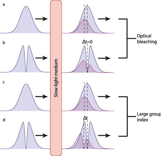
Figure 1. Distortion of an incident pulse passing through a slow-light medium. Part (a) shows a single pulse passing through the slow-light medium. Optical bleaching (a) and large group index (c) effects are indistinguishable for small delay of a single pulse, typical of most experimental conditions. To distinguish the two cases, one can pass a pulse with an imprinted zero through the slow-light medium. Optical bleaching and pulse reshaping would never cause the position of the dark region to shift, although it may become brighter due to fluorescence from the saturable absorber (b), an effect that is in agreement with [14]. However, large group index would cause the position of the dark region to be maintained but shifted (d). By imprinting an intensity zero in the pulse, we can determine which mechanism is causing the apparent slowing of the light through the ruby, even with a small delay.
Download figure:
Standard image High-resolution imageRecognizing the nonlinear nature of our experiment, it is nonetheless useful to consider the effects of the Kramers–Kronig relation. The Kramers–Kronig relation describes the link between the intensity absorption coefficient, α, and the phase index:

where P is the Cauchy principal value, ω is the frequency of the light and c is the speed of light in a vacuum. The phase index is calculated over all frequencies, Ω [15]. In the case of slow light, the narrow absorption band gives rise to a large dispersion in nϕ. We can use nϕ to calculate the group index, ng, by

leading to a large ng. In turn, for large ng, the simple definition of vg = c/ng gives a small group velocity, vg, which is the basis of material slow light.
As one example of slow light, we recently showed that slow-light effects could be observed in the spatial domain [17]. The transverse movement of an optical medium is known to laterally displace a transmitted light beam [18]. Although predicted many years ago, such photon drag effects are usually very small and difficult to observe. In addition to lateral displacement, a spinning medium was also shown to cause a rotation of the polarization state [19], termed the mechanical Faraday effect [20]. Through the equivalence of spin and orbital angular momentum, the rotation of the medium affects both the polarization and the transmitted image [21, 22]. This image rotation, Δθimage, is given by

Here Ω is the angular velocity of the medium and L is its length. Since ng is of order unity for ordinary materials, an image rotation caused by a spinning medium is on the order of a few microradians. We have shown that the increase in propagation time of light in a slow-light medium leads to a large increase in the rotation [17]. Specifically, we observed that transmission through a spinning ruby window would rotate an elliptical beam profile by many degrees, a demonstration of slow-light-enhanced rotary photon drag. However, in that experiment, the simple rotation of a bright line could not distinguish between optical bleaching and an increase in the group index arising from the dispersion. It is interesting to note the differences between lateral and rotational photon drag, namely that rotational photon drag could be complicated by the Coriolis effect [23], although our results remain consistent with equation (3).
To determine whether the rotation of the elliptical beam profile [17] arises from optical bleaching or an increase in ng that arises from the dispersion, we study an intensity null in the centre of a high-intensity pulse. Our present experiment is motivated by the realization that, whereas it is difficult to create an intensity null in the temporal domain, it is easy to do so in the spatial domain. To create this null, we introduce a π-radian phase step into our beam cross section, which creates a black line across the beam that is stable upon propagation. Given that the slow-light effect, and thus rotary photon drag, is dependent on self-pumping at high intensity, the question then posed is whether a spinning medium can rotate the orientation of a structured beam containing both bright and dark regions.
As shown in figure 2, we use a 3 W beam from a laser quantum opus solid state, diode-pumped laser. The linearly polarized 532 nm light is passed through a quarter waveplate to create circularly polarized light. Using circularly polarized light ensures rotational symmetry, which is important as ruby is birefringent. This circularly polarized light is then expanded through 40 and 60 mm focal-length cylindrical lenses, resulting in a collimated, elliptical beam. The beam enters the ruby as an elongated spot, as seen in figure 3. A spherical lens with a focal length of 60 mm focuses the beam onto the front face of a 6 mm-thick standard laser ruby crystal window, along the window's rotational axis. When pumped with 532 nm light, the ruby acts as a slow-light medium, and thus as the light passes through the ruby window, its group velocity is effectively slowed to tens of meters per second.

Figure 2. Experimental procedure. A beam of 3 W, 532 nm light is bisected by a coverslip. The entire beam then passes through a quarter waveplate, two cylindrical telescoping lenses and is focused on a ruby window. The ruby is spun to ≈ ± 20 rotations per second (rps), and the light leaving the ruby is imaged onto a camera.
Download figure:
Standard image High-resolution image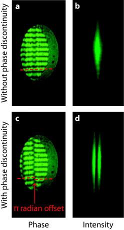
Figure 3. Images of the beam profile when a microscope coverslip is inserted halfway into the beam. The coverslip can be tilted so (a, b) there is no phase shift or (c, d) there is a π-radian phase shift between the two halves of the beam. Figures (a) and (c) are taken before the ruby and use a shear plate to show the interference pattern for the coverslip set to two different thicknesses. These images show that tilting the coverslip does create a π-radian phase shift between the two halves. Figures (b) and (d) show the corresponding intensity profiles after the ruby. Note the creation of an intensity null in (d).
Download figure:
Standard image High-resolution imageA Parker Hannifin, SY-series stepper motor with a built-in ViX250IM controller has encoders that allow us to accurately control the rotation rate of the ruby. A toothed drive belt and pulley couple the motor to the ruby mount in a 1:1 gear arrangement. The motor has encoders that spin the ruby window about its axis up to ≈ ± 20 rps. Software control of both rotation rate and direction is easily achieved using a standard desktop PC computer interface and a National Instruments LabVIEW Virtual Instrument. The magnitude of the image rotation is dependent upon the angular frequency at which the ruby spins [16]. Below ±10 rps, there is a near-linear dependence on angular frequency, as described in equation (3). Above ±10 rps, the dependence levels out with little noticeable increase in effect as the angular speed is increased, as a consequence of the 20 ms upper-state lifetime of the ruby and the corresponding relaxation time of 3 ms, which limit its response. The beam is imaged from the back face of the ruby onto a Dalsa Genie CCD array and recorded for subsequent analysis using another National Instruments LabVIEW Virtual Instrument.
In order to introduce the black line into the elliptical beam, we mount a glass coverslip onto a tilt stage and insert it halfway into the output beam of the laser, as shown in figure 2. The tilt stage allows us to adjust the orientation and therefore the thickness of the glass through which the light is travelling. At the correct tilt angle, the difference in path lengths causes a π-radian phase discontinuity between the two halves of the beam, as shown in figure 3. This phase discontinuity creates a line of darkness, with a contrast limited only by scattering and crosstalk between pixels, in an otherwise high-intensity beam. We estimate that the intensity of the incident beam exceeds the saturation intensity by a factor of 4 or 5. By contrast, as measured from the camera image, the dark line (which is ideally of zero intensity but may be subject to experimental imperfection) is at least an order of magnitude darker than this.
Images of the light beam transmitted by the ruby are recorded, and representative images from our results are shown in figure 4. As the direction of the rotation of the ruby window is changed, we see that the elliptical beam becomes rotated about 5.0 ± 2°, preserving the structure such that the dark region is also rotated through a similar angle. From equation (3), a rotation of 5.0 ± 2° implies an effective ng of 3.6 × 10⁷ ± 0.9, which corresponds to a group velocity of vg = 8.3 ± 0.3 m s−1. We find a radial dependence in the rotation angle, which we ascribe to the intensity dependence of the group index, resulting in an S-shape of both the transmitted beam and the phase discontinuity. The introduction of light where there had previously been a black region and, more importantly, the creation of a black region where there had previously been light (see figure 5) imply that the slow-light phenomenon is complex and cannot be described by a simple model of optical bleaching and pulse reshaping.

Figure 4. Images of the beam (a) without the phase discontinuity and (b) with the phase discontinuity when the ruby is spinning from −19 to +19 rps.
Download figure:
Standard image High-resolution image
Figure 5. Graph of results. A strip of the beam profile at the radius with the greatest photon drag is unwrapped in (a) when the ruby is spinning anticlockwise (blue), clockwise (pink) and removed from the setup (beige). The intensity of each of those strips is plotted in (b). The blue and pink curves show the position of the region of darkness while spinning anticlockwise and clockwise, respectively, to be outside the position of the dark region when the ruby is removed. One observation in this figure is the movement of the dark line causing there to be light in the clockwise and anticlockwise cases where there had been darkness in the stopped case, which could be explained by fluorescence from the saturable absorber. However, the region of darkness is preserved through the rotation to a position that had previously been bright.
Download figure:
Standard image High-resolution image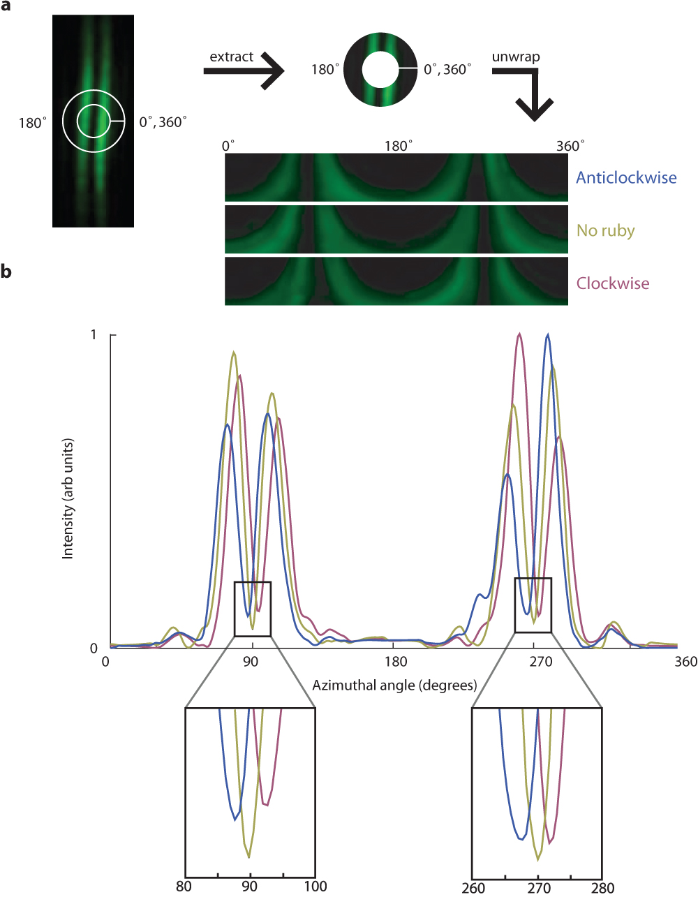
In summary, we have found that passing an image through a spinning, self-pumped, slow-light medium rotates the bright and dark regions by the same amount and that light in the output cross section is azimuthally displaced to positions where the input beam was dark. Such displacements cannot be explained solely by optical bleaching, since such effects cannot lead to a shift in a region of darkness. As such, rather than optical bleaching, it appears that narrow band absorption, and the associated change in group refractive index, are responsible for our observed slowing. These results further the understanding of the mechanisms that cause slow light and pave the way for applications dependent on the preservation of complex patterns in slow-light media. The rotation of the structured beam implies the preservation of the coherence between the modes in the basis set from which pattern is formed. Hence this modal coherence has important implications for optical storage and optical memory.
Acknowledgments
This research was funded by EPSRC. ELW-B is supported by the Scottish Universities Physics Alliance, and MJP was supported by the Royal Society. RWB gratefully acknowledges support from the US Defense Threat Reduction Agency. All authors contributed equally to this work. The authors declare no competing financial interests.