


Abstract
We report on the possibility of diffracting electrons from light waves traveling inside a dielectric medium. We show that, in the frame of reference which moves with the group velocity of light, the traveling wave acts as a stationary diffraction grating from which electrons can diffract, similar to the conventional Kapitza–Dirac effect. To characterize the Kapitza–Dirac effect with traveling light waves, we make use of the Hamiltonian Analogy between electron optics and quantum mechanics and apply the Helmholtz–Kirchhoff theory of diffraction.
General Scientific Summary
Introduction and background. The Kapitza-Dirac effect, i.e. the diffraction of electrons from a periodic light wave, has been predicted in the 1930's. Only now, with the advent of sufficiently intense lasers, it became possible to observe the effect experimentally. Commonly a standing wave is used to create the diffraction grating, but also other configurations, involving counter propagating waves of different frequencies have been considered in the past. In this paper, we address the question whether it is possible to observe the effect with a single light beam, travelling with a reduced group velocity within a dielectric medium.
Main results. We confirm that the Kapitza-Dirac effect can be observed with a single beam of light, provided the longitudinal velocity of the electrons is commensurate with the reduced group velocity. Using Lorentz transformations between a laboratory and reference frame associated with the travelling light field, we show that in this frame of reference the light acts as a stationary diffraction grating for electrons. In contrast to a standing wave, a single, travelling light wave can give rise to inelastic diffraction when electrons exchanges energy with the light field.
Wider implications. Diffraction phenomena occur for all kinds of waves and represent a signature of fundamental interference processes. Our extension of the standard Kapitza-Dirac effect to the case of a single light beam enlarges the scope to observe such effects, and might lead to simplified schemes in interferometry and microscopy.
Figure. Geometry of the electron diffraction in the laboratory (a) and wave (b) frames of reference. Electrons overtake the slowed light and experience diffraction for specific angles (c). The "butterfly wings" represent the regions where the Kapitza-Dirac effect with traveling waves occurs (c). Download figure:
Export citation and abstract BibTeX RIS

Content from this work may be used under the terms of the Creative Commons Attribution 3.0 licence. Any further distribution of this work must maintain attribution to the author(s) and the title of the work, journal citation and DOI.
General Scientific Summary
Introduction and background. The Kapitza-Dirac effect, i.e. the diffraction of electrons from a periodic light wave, has been predicted in the 1930's. Only now, with the advent of sufficiently intense lasers, it became possible to observe the effect experimentally. Commonly a standing wave is used to create the diffraction grating, but also other configurations, involving counter propagating waves of different frequencies have been considered in the past. In this paper, we address the question whether it is possible to observe the effect with a single light beam, travelling with a reduced group velocity within a dielectric medium.
Main results. We confirm that the Kapitza-Dirac effect can be observed with a single beam of light, provided the longitudinal velocity of the electrons is commensurate with the reduced group velocity. Using Lorentz transformations between a laboratory and reference frame associated with the travelling light field, we show that in this frame of reference the light acts as a stationary diffraction grating for electrons. In contrast to a standing wave, a single, travelling light wave can give rise to inelastic diffraction when electrons exchanges energy with the light field.
Wider implications. Diffraction phenomena occur for all kinds of waves and represent a signature of fundamental interference processes. Our extension of the standard Kapitza-Dirac effect to the case of a single light beam enlarges the scope to observe such effects, and might lead to simplified schemes in interferometry and microscopy.
 Figure. Geometry of the electron diffraction in the laboratory (a) and wave (b) frames of reference. Electrons overtake the slowed light and experience diffraction for specific angles (c). The "butterfly wings" represent the regions where the Kapitza-Dirac effect with traveling waves occurs (c).
1. Introduction
In the beginning of the 1930s, Kapitza and Dirac predicted that electrons can pass through the regular structure of a standing light wave and diffract [1], a phenomenon nowadays known as the Kapitza–Dirac effect (KDE) [2, 3]. In this process, the conventional roles of waves and matter are interchanged, as the light acts as a diffraction grating for electrons, similar to the diffraction of electrons by a periodic lattice of crystals, first observed by Davisson and Germer [4]. Early attempts to measure the KDE were unsuccessful due to the lack of strong light sources [5, 6]. With the development of the laser and the subsequent increase to ever higher intensities, electron–light interactions have been enhanced to a degree that enabled the observation of high intensity scattering [7] and diffraction [8, 9] of electrons from a standing light wave, thus confirming the prediction of the original paper [1]. The experimental evidence has further stimulated advanced theoretical treatments of the KDE to simultaneously explain both the scattering and diffraction of electrons [10], to extend the KDE for two-particle systems [11] and to account for spin effects [12, 13].
Although we can think of the conventional KDE as the diffraction of electrons from a standing light wave, Smirnova et al asked the question as to whether this effect can be generalized to other configurations of laser beams [14]. Using two laser beams with different colors they showed that the electron can still experience diffraction due to its non-linear response to the field creating a stationary grating from which the electron scatters. Very recently, the KDE for a general configuration was investigated in [15], but it is interesting to note that the idea of using two light beams with distinct frequencies stems from the earlier work of Haroutunian and Avetissian [16], who discuss an analogous effect in the non-stationary regime.
In this paper, we go a step forward and demonstrate that the KDE can also be realized with a single traveling light wave propagating in a dielectric medium. The presence of a medium enables us to associate a frame of reference with the wave which moves with a group velocity of less than the speed of light in vacuum. In this wave frame of reference (WFR), we show that the traveling wave acts as a stationary diffraction grating for electrons: while in the laboratory frame of reference (LFR), electrons are incident obliquely on the traveling wave, in the WFR the electron beam impinges perpendicularly on the diffraction grating as we tune the electron velocity and incident angle such that it 'sees' the wave at rest. In this reduced geometry, we utilize the Hamiltonian Analogy between electron optics and quantum mechanics in order to describe the 'trajectory' of electrons in an external potential field by their path through a periodically varying 'refractive index' induced by the light field within the dielectric medium. In this approach, we apply the Helmholtz–Kirchhoff theory of diffraction and work in the far-field (Fraunhofer) approximation, that is we look at the diffracted electrons a long way from the light field. This allows us to determine the range of electron beam parameters, in particular the incident angle and the initial energy, to demonstrate the possibility of realizing the KDE with traveling waves, unique in its kind.
The paper is structured as follows. In the next section, the geometry of electron diffraction from a traveling wave of laser light is introduced in both the LFR and WFR by employing the Lorentz transformations for electron energy and momentum. These Lorentz transformed quantities are then used in section 3 to derive a diffraction theory by accounting for the correspondence between electron optics and quantum mechanics, known as the Hamiltonian analogy. In section 4, we discuss the diffraction condition as well as the predicted range of electron and laser beam parameters for which the KDE can be realized. Finally, a few conclusions are drawn in the last section.
2. Diffraction geometry in the laboratory and wave frames of reference
In order to treat the diffraction scattering of electrons from traveling light waves in the presence of a dielectric medium, we define the diffraction geometry in two different frames of reference: (i) in the LFR where the observer is at rest, and (ii) in the WFR which is at rest with respect to the light propagating with slowed down velocity. Given that the electron velocity must be commensurate with the group velocity of light to experience diffraction, we will henceforth adopt relativistic kinematics. In this scenario, let us assume an electron with mass m and charge  impinges—in the LFR—under an incident angle θi≡θ on the linearly polarized laser beam traveling through a dielectric medium characterized by the refractive index n (cf figure 1(a)). If we now correspondingly choose the x- and y-axes along the propagation and polarization directions of the laser, its four-vector potential and the wave four-vector can be written as


where  . The constant amplitude
  here defines the (time-averaged) intensity of the laser beam,
  in Gaussian units, with c being the speed of light in vacuum, while ω and
  represent respectively the angular frequency and wave number. Furthermore, we express the initial four-momentum of the electron via

where the energy  and the three-dimensional momentum
  are related through the standard relativistic energy–momentum relation,
  . In addition, for the sake of simplicity we choose
  implying that the diffraction process occurs in the
  -plane.

Figure 1. Geometry of electron diffraction from a traveling wave in the presence of dielectric media. In the LFR (a), the electron beam (blue coloring) impinges under an incident angle θi on the traveling light with the wavelength λ (red waveform). Whereas in the WFR (b), the electron beam (blue coloring) is incident perpendicularly to the stationary grating with the period  (red ellipses). The velocity of the WFR with respect to the LFR is associated with the group velocity of the light,
  .
.
Download figure:
Standard image High-resolution imageIn order to show how the traveling wave (1) gives rise to a stationary (i.e. time-independent) diffraction grating in the presence of dielectric media, we associate a frame of reference with the light beam that moves with the group velocity  , where
  is the modulus of the group velocity and
  is the unit vector of the x-axis. In this frame of reference, the four-coordinates
  are transformed by the Lorentz boost along the x-axis

where  is the four-coordinate as seen from the moving wave, and 'tilde' denotes quantities in the WFR. As the field is polarized linearly, perpendicular to the Lorentz boost, the amplitude of the vector-potential remains unchanged,
  , whereas the phase
  is modified (as compared with equation (1)) due to the transformations (4)

Here,  represents the wave number of light in the WFR and at the same time defines the period of the diffraction grating,
  (cf figure 1(b)). The fact that the coefficient in front of the Lorentz-transformed time coordinate
  equals zero, that is
  , confirms that the potential in the WFR is indeed stationary. As one would expect, the constructed time-independent potential (5) is a solution to Maxwell's equations with the Minkowski constitutive relations in moving media [17].
We are interested in a particular geometry in the WFR where the electron beam impinges perpendicularly on the light beam, as in the conventional KDE in the Raman–Nath regime [2, 3, 18, 19]. To this end, we tune the electron velocity in the LFR such that it 'sees' the wave at rest in the WFR. To implement this scenario, we require the longitudinal velocity of the electron beam to be equal to the group velocity of the traveling wave,  . For such a condition, we perform Lorentz transformations for the four-momentum in the LFR (3)

and obtain the desired form of the four-momentum in the WFR

with  , as also illustrated in figure 1(b). Using both the wave vector (5) and four-momentum (7), we investigate in the following the intensity of electron diffraction scattering and the momentum transfer of the diffracted electron in the WFR.
3. Helmholtz–Kirchhoff theory of the Kapitza–Dirac effect with traveling light waves
To show the possibility of demonstrating the KDE with traveling waves, we follow Ehlotzky and Leubner [20, 21] and employ the Hamiltonian Analogy which explains the 'trajectory' of material particles in external fields by the 'optical path' in media with a variable 'refractive index' (see [22–25] and references therein for an overview on the Hamiltonian analogy)3
. We therefore assume that the laser beam acts as a refractive medium for electrons propagating along an 'optical path'. With this distinction between the roles of wave and matter we shall characterize the laser beam through a 'refractive index'  and the passage of electrons through light via a transmission function
  . Throughout this section we work in the WFR.
It is important to estimate the validity of the Hamiltonian Analogy and the subsequent Fraunhofer approximation for calculating the far field of the diffracted electrons. In order to ensure that the electron propagates along an 'optical path' inside the laser beam, we shall adopt the following assumption: the electron–laser interaction time  should be sufficiently small, so that very few deflections of electrons occur. In order to relate this condition to external parameters, such as the beamwidth, intensity and frequency of the light and also to the refractive index of the medium, we use the definitions of the electric field and the magnetic induction in terms of the vector potential,
  ,
,  , where
  is the vector differential operator and 'cross' means vector product. By using equation (5), we get
  and
and  , that is, the electric field is zero in the WFR, while the magnetic induction becomes time independent. In such a configuration, electrons experience a helical motion with the axis of the helix along the magnetic field (
 -axis) [26]. The helix, moreover, is characterized by its radius of curvature
  . Due to the short time of interaction, the radius of curvature is larger than the transverse extension of the laser beam,
  . This condition in turn can be expressed via a dimensionless parameter
  , which retains the same value in both frames of references.
Using the Hamiltonian Analogy, we define a 'refractive index' for electrons as the ratio of the kinetic momentum of the electron in- and outside the traveling wave,  [20, 21, 28, 29]. One can use the energy conservation law in the WFR

and combine it with equation (5), in order to obtain the explicit form of the 'refractive index'

which is a periodic function in  with a period of
  ,
,  , where
  is an integer. We have here neglected the angle between the momentum
  and the vector potential
  in view of the Fraunhofer approximation. The 'refractive index'
  acts as an electron-optical analogue of the (time-independent) ponderomotive potential which leads to the conventional KDE [2, 3]. Note that using the canonical momentum for the definition of
  instead would not affect our forthcoming discussion. This is reminiscent of the resolution to the Abraham–Minkowski controversy [30, 31], concerning the definition of optical momentum in dielectric media [32, 33] (see [34] for a recent experiment).
We are now ready to define the transmission function for electrons passing through the light beam. To this end, we make use of the following ansatz for the electron wave function (without spin)

where  is a constant amplitude that determines the intensity of the electron before entering the light beam,
  , and
, and  is a smoothly changing function which slightly modifies the amplitude of the wave function. Owing to the short interaction time of the electron with light, however, we may simply take
  . In this eikonal approximation, the wave influences only the phase of the electron beam by giving rise to the propagation of the electron along the 'optical path'
  such that it experiences a diffraction from the phase grating (8)4
. We can therefore define the transmission function as
such that it experiences a diffraction from the phase grating (8)4
. We can therefore define the transmission function as  [20, 21], which yields

This is again a periodic function of  with the same periodicity as the 'refractive index' (8). Moreover,
  in the absence of the light or else in the absence of the diffraction grating, i.e. when
  .
.
In order to ascertain the disturbance of electrons at a long distance from the light beam, we apply here the Helmholtz–Kirchhoff theory in the far-field approximation. This approximation manifests itself in the Fraunhofer integral [22]

where  is a constant number, which depends on the intensity of the electron, and the properties of light in the medium, and
  is the angle between the initial and scattered momenta—the diffraction angle—in the WFR (cf figure 1(b)). Moreover,
  is the diameter of the electron beam, which also represents the (one-dimensional) size of the diffracting aperture, sufficiently larger compared to the wavelength of light,
  , to avoid edge effects. Given this condition, we can make the replacement
  , where N is a large non-negative integer. By taking into account the periodicity of the transmission function
  and using geometric progression, we can reduce the integral (11) to

where

resembles a Fraunhofer integral, but with the reduced 'aperture size'  .
.
The main characteristics of the diffraction scattering (the principal maxima and the intensity of the diffraction pattern) can be determined via the 'disturbed' wave (12). To do so, we calculate the modulus-squared of equation (12), i.e. the intensity of diffracted electrons

and readily recognize that this equation has maxima whenever  , with s being an integer. As the term
  represents the momentum transfer from/to the laser beam, the term
  exhibits the geometrical inclination of the electron's momentum from its initial direction (cf figure 1(b)). We can therefore interpret s as the number of photons absorbed (
 ) or emitted (
 ) by the electron during the diffraction process, such that the final electron momentum in the direction of laser propagation takes the form

By inserting equations (8) and (10) into equation (13) and utilizing the integral representation of the Bessel function of the first kind with integer order s,  , we can analytically evaluate the integral (13)
To get the constant  , moreover, we switch off the light by setting
  and
and  , and make use of equations (11) and (14), resulting in
  . This in turn gives rise to the exact intensity distribution of the diffraction pattern

which is independent of the choice of the frame of reference and establishes a connection between the laser and electron beam parameters. In addition, the expression (16) can be approximated via  for very small values of Δ.
We have derived the Helmholtz–Kirchhoff theory of the KDE with traveling light waves in the WFR and have determined the momentum transfer (15) from/to the laser due to the diffraction scattering. By Lorentz transforming back to the LFR in the following, we shall show how this momentum transfer manifests itself in the diffraction condition.
4. Results and discussion
To exhibit the range of electron beam parameters for which the KDE with traveling waves occurs, that is, to ascertain the diffraction condition, we establish relations in the LFR between (i) the diffraction and incident angles and (ii) the diffraction angle and the initial energy. For this purpose, we make use of equation (15) for the momentum transfer and write the final electron four-momentum in the WFR as

where the momentum conservation perpendicular to the light propagation direction is assumed,  , since the 'refractive index'
  acting as a ponderomotive potential varies as a function of the longitudinal coordinate x (or
  , see equation (8)). The inverse Lorentz transformations from the WFR to the LFR,
lead to the following form for the final electron four-momentum

Here,  is the momentum transfer that gives rise to the electron diffraction by the traveling wave, unlike the analogous term
  in the conventional KDE with standing waves [2, 3, 20, 21]. Another peculiar feature of the KDE with traveling waves is that while the electron undergoes elastic scattering in the WFR (
 ), the diffraction has an inelastic nature in the LFR (
 ), as seen from equations (3), (7), (17) and (18).
The diffraction angle ϑ, defined as the angle between the initial and final directions of the electron momentum, has the form  . This expression, along with equations (3) and (18), results in


where the relativistic expressions for electron momentum and energy are used:  and
and  . Owing to the non-zero longitudinal velocity of the electron, which is assumed to be equal to the group velocity of light in a dielectric medium,
  , the values of the incident angle and that of the initial energy are restricted by the conditions

These constraints manifest themselves in the diffraction conditions (19)–(20) and define the range of electron beam parameters for which the KDE with traveling waves takes place. The effect can be shown for a variety of dielectric materials in which the group velocity of light is less than c, provided the material has no internal structure, such as an amorphous glass or even air. For illustration purposes we fix the wavelength to be λ=630nm and two materials (glass and air) with refractive indices n=1.48 and n=1.0003. The corresponding values of the laser angular frequency and group velocity will then be  Hz,
Hz,  for glass and
  Hz,
Hz,  for air. While in the case of glass the diffraction angle and the electron energy correspondingly vary in the range of a few μrad and several MeV, electrons with energy of a few hundreds of MeV are required to experience diffraction (under angles of few nanoradians) from light shining in the air. The gaps between the 'butterfly wings' in figures 2(a) and 3(a) mark out the limits of the incident angle beyond which the effect no longer occurs due to the constraints (21). As can also be seen, the more photons participate in the diffraction process, the larger the diffraction angle. However, the multi-photon interaction with the laser field is less probable, compared to the single-photon interaction, since the electron intensity (i.e. the probability density) decreases while the number of photons increases, as can clearly be seen from equation (16). To compare diffraction probabilities for different diffraction orders (
 ), we normalise the electron intensity to the intensity of the zeroth-order diffraction, that is the intensity of the forward-scattered electron which does not absorb or emit any photons. The relative intensities,
  , are depicted in figure 4. As we increase the laser intensity, but keep the beamwidth the same (
 μm), each of the relative intensities of diffracted electrons increases and scales with
  based on the geometrical optics approximation for electrons. This gives rise to different slopes for the single-photon interaction,
  , and more pronounced differences for the quadratic and cubic curves representing the two- and three-photon interactions, respectively.
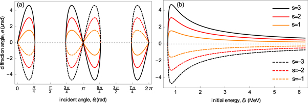
Figure 2. Plot of the electron diffraction angle (in μrad) as a function of incident angle (in rad) (a) and initial electron energy (in MeV) (b) for different photon numbers s, when the electron experiences diffraction from light traveling through the glass. Solid (dashed) curves correspond to positive (negative) values of s;  are indicated by 'orange', 'red' and 'black', respectively. The
  dotted line represents the case of the forward scattering (s = 0).
Download figure:
Standard image High-resolution image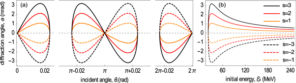
Figure 3. Electron diffraction angle (in nrad) as a function of incident angle (in rad) (a) and initial electron energy (in MeV) (b), when the light passes through the air. Designations of curves are the same as in figure 2.
Download figure:
Standard image High-resolution image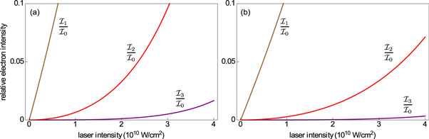
Figure 4. Relative electron intensity (normalized to the intensity of the forward-scattered electron) as a function of the laser intensity (in units of 1010 W/cm2). Comparison is made between one- (brown), two- (red), and three-photon (purple) processes when the light shines in the glass (a) or air (b).
Download figure:
Standard image High-resolution imageWe should mention that the diffraction condition in either forms of (19) or (20) holds provided that the recoil energy loss of the scattered electron both from the light and medium is neglected. Such an approximation is valid for (i) sufficiently thin layers of dielectrics (having almost the same width as the diameter of the laser) and (ii) low energies of photons (as compared to the energy of electrons). These two requirements are simultaneously fulfilled for high energy relativistic electrons that are available, for example, at the German Electron Synchrotron (DESY) in Hamburg. A rigorous study of the 'electron–light–matter' interaction to account for the multiple scattering of electrons in media [37, 38] would constitute correction to the diffraction condition.
The effect we communicate here is similar to the KDE with standing waves, yet endowed with peculiar properties. In contrast to the conventional KDE, where the electron experiences a diffraction by simultaneously absorbing and emitting photon(s) from the standing wave of two counter-propagating lasers, in our case, the electron diffracts by either absorbing ( ) or emitting (
 ) photon(s) from a single traveling wave. Another important difference is that while in the Raman–Nath regime the electron beam is incident perpendicularly to the standing wave, here, the beam always impinges obliquely on the traveling wave, exclusively, in the presence of a dielectric medium. It is the dielectric medium that allows one to consider an electron with the same longitudinal velocity as the group velocity of light in order to assure that the electron 'overtakes' and 'feels' the wave at rest, as a stationary diffraction grating. Per se, our results have implications in the optics of moving media, where the relative velocities are comparable to the group velocity of the light [39, 40].
5. Conclusion
We have reported on the possibility of the KDE with traveling waves in the presence of dielectric media. We have demonstrated that even without the standing-wave condition, the light can act as a diffraction grating for electrons that have the same longitudinal velocity as the group velocity of light. In our case, the electron experiences inelastic diffraction scattering, as opposed to the conventional KDE in which no energy exchange occurs between the electron and laser light. By calculating the intensity distribution and the angle of diffraction, we have estimated the range of electron beam parameters in experimentally realistic situations where the KDE with traveling light can occur. We do expect that the effect can be observed, as there is a remarkable experiment on diffraction of atoms by 'slowly traveling standing waves' which shares common features with our 'set up' [41]. The approach taken in our paper can be applied for studying similar effects also with spin-polarized relativistic electrons both without [12, 13] and with twist [42, 43] when diffracted from various configurations of phase gratings [44, 45]. Diffracted electrons may also be used for studying form factors via radiation assisted electron scattering [46, 47].
In recent years, the reduction of the speed of light both for structured beams in free space [48] and for the so-called surface plasmon polaritons at a metal–vacuum interface [49] has raised considerable interest. Investigation of diffraction phenomena with such slowed down waves is our forthcoming target.
Acknowledgments
We appreciate insightful discussions with Klaus Hornberger and Mark Dennis.
Footnotes
- 3
- 4
