


Abstract
Quantum key distribution (QKD) has been studied for achieving perfectly secure cryptography based on quantum mechanics. This paper presents a novel QKD scheme that is based on an intensity-modulation and direct-detection system. Two slightly intensity-modulated pulses are sent from a transmitter, and a receiver determines key bits from the directly detected intensity. We analyzed the system performance for two typical eavesdropping methods, a beam splitting attack and an intercept-resend attack, with an assumption that the transmitting and receiving devices are fully trusted. Our brief analysis showed that short- or middle-range QKD systems are achievable with a simple setup.
Export citation and abstract BibTeX RIS

Original content from this work may be used under the terms of the Creative Commons Attribution 3.0 licence. Any further distribution of this work must maintain attribution to the author(s) and the title of the work, journal citation and DOI.
1. Introduction
Quantum key distribution (QKD) has been studied for achieving perfectly secure cryptography. There are two main kinds of QKD scheme: single-photon-based QKD [1, 2] and continuous-variable QKD (CVQKD) [3, 4]. Single-photon-based QKD has the advantage of enabling long-range key distribution, whereas one disadvantage is that bulky and expensive single-photon detectors are required. CVQKD avoids this disadvantage by employing homodyne detection with conventional photodiodes. However, homodyne detection requires phase-stabilized local light, which is not easy to implement. Based on the above background, we previously proposed differential-phase-shift-keying (DPSK)-based CVQKD [5, 6]. A phase-modulated coherent pulse train with moderate power is transmitted, and it is detected using a delay Mach–Zehnder interferometer. Each pulse simultaneously acts as signal and local lights in this scheme, therefore, this method requires no external local light.
This paper presents a novel CVQKD scheme, which utilizes direct detection. Intensity-modulated (IM) coherent light with moderate power is transmitted and directly detected (DD). IM/DD systems are simpler than DPSK systems, as they do not use a delay interferometer, and have been well-developed in conventional optical communications. The present scheme achieves the QKD function with a simple setup.
2. Protocol and security
Figure 1 shows a schematic of the proposed IM/DD QKD system, in which the transmitter and receiver are called Alice and Bob, respectively. The protocol of this system is as follows.
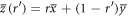
- (i)Alice transmits signal light, which is slightly intensity-modulated according to binary random numbers 0 or 1 as I or
 , at a moderate power level.
 - (ii)Bob directly detects the transmitted light. The measured signal levels are distributed because of noise, as shown in figure 2. The distribution has two peaks, corresponding to Alice's binary intensity modulation I and, that overlap with each other because δ is small compared to the noise variances.
- (iii)Bob sets two thresholds at high and low levels d0 and d1, respectively, for the signal distribution, as shown in figure 2. When the measured signal is smaller than the lower threshold d0, he creates bit 0. When the signal is larger than the higher threshold d1, he creates bit 1. Otherwise, he creates no bit (called bit X).
- (iv)Using a classical communication channel, Bob tells Alice the time of the signals from which he created bits. Alice creates bit 0 or 1 when the corresponding signal intensity is I or, respectively. Then, Alice and Bob share an identical bit string, which can be a secret key.


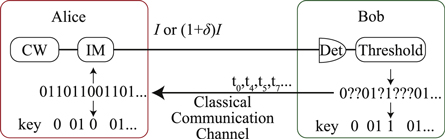
Figure 1. IM/DD QKD system. CW is a continuous-wave laser, IM is an intensity modulator, Det is a photo detector, and Threshold is a comparator. Alice transmits signal light with a power level of I or  based on binary random numbers. Bob receives the light and estimates the original binary data. When Bob creates bits, he tells Alice of the bit creation time using a classical communication channel. Hereby, Alice and Bob can share a secret key.
Download figure:
Standard image High-resolution image
Figure 2. The distribution of Bob's received current signal.
Download figure:
Standard image High-resolution imageThe security of this protocol is based on the fact that two coherent states with a small amplitude difference are nonorthogonal to each other. Because of this nonorthogonality, an eavesdropper, Eve, cannot fully distinguish the transmitted state. She may set thresholds and obtain the key bits as Bob does. However, when she conducts this measurement while beam-splitting the transmitted signal, for example, the received signals fluctuate differently in Eve and Bob because the quantum noises of the beam-split lights have no correlation, and thus, the key bits created by Bob and Eve do not match. Eve may try this measurement of setting thresholds while intercepting and resending the transmitted signal. However, Eve sometimes (or most of the time) obtains no bit and is forced to resend randomly intensity-modulated signals, which cause Bob's bit errors and reveal eavesdropping. Note that Eve is not allowed to resend nothing when obtaining no bit, because a moderate signal power is transmitted from Alice to Bob, unlike in single-photon-based QKD, and thus, every signal is expected to be detected by Bob.
3. System performance evaluation
In this section, we describe a system performance evaluation of the above-described IM/DD QKD method, assuming specific eavesdropping, a beam splitting attack (BSA), and an intercept-resend attack (IRA). General attacks are not considered because this paper is proposing a novel QKD protocol featuring practicality, and a detailed theoretical analysis is beyond the scope of the present paper. We assume throughout this paper that all the devices Alice and Bob use are fully trusted and work with an arbitrary precision, in order to evaluate the basic performance of the present protocol.
3.1. Mutual information
From the information theoretical point of view, the final key creation rate after error correction and privacy amplification, i.e. the secure key creation rate, Rf, is given by

where RAB, RAE, and RBE are the mutual information between Alice and Bob, that between Alice and Eve, and that between Bob and Eve, respectively.
Which expression, RAE or RBE, in (1) is employed depends on the method of error correction, i.e., bidirectional or reverse reconciliation. In the former case, Eve obtains the error correcting information exchanged between Alice and Bob, and the final key rate should be ![${R}_{f}={R}_{\mathrm{AB}}-\mathrm{max}[{R}_{\mathrm{AE}},{R}_{\mathrm{BE}}]$](https://content.cld.iop.org/journals/1367-2630/18/1/013018/revision1/njpaa0d9fieqn5.gif) so as to exclude Eve's information from the key. In the later case, on the other hand, Eve only obtains the error correcting information sent from Bob to Alice, and the final key rate should be
so as to exclude Eve's information from the key. In the later case, on the other hand, Eve only obtains the error correcting information sent from Bob to Alice, and the final key rate should be  so as to exclude Eve's information obtained from Bob. Generally, the mutual information between Bob and Eve, RBE, is smaller than that between Alice and Eve, RAE. Thus, reverse reconciliation offers a higher final key creation rate.
In the following sections, we evaluate the above-described mutual information in our QKD system, utilizing the following formula [7]:

In the above expression, RXY is mutual information between X and Y, PX(x) and PY(y) are probabilities that X and Y create x and y, respectively, and  is the joint probability that X's bit x coincides with Y's bit y. To be specific, we evaluate the joint probability between Alice and Bob, that between Alice and Eve, and that between Bob and Eve, and then, evaluate the mutual information by substituting them into (2). In practice, the error correction efficiency should be taken into account in estimating RAB. In this paper, however, we assume 100% error correction efficiency in order to evaluate the upper bound of the performance of our protocol.
3.2. Joint probability between Alice and Bob
In this subsection, we derive the joint probabilities between Alice and Bob, and evaluate the mutual information between them. First, we evaluate the distribution of the photo-current signal at Bob's detector, which suffers from some kinds of noise. Here, we assume three kinds of additive white Gaussian noise (AWGN): optical classical noise, optical quantum noise, and electrical thermal noise. Classical noise is mainly caused by the non-ideal light source, whose noise power  is proportional to the square of the light intensity. Quantum noise is inherent in the nature of photons, whose power
  is proportional to the light intensity. Thermal noise is caused by the thermal motion of electrons in receiver circuits, whose power
  is independent of the light intensity. Taking these noise characteristics into account, the mean value i0 and the variance
  of Bob's signal for Alice's signal of intensity of I0 are expressed as


where B is the base-band width of the receiver, T is the fiber transmittance, η is the quantum efficiency of the detector, a, b, and c are proportionality constants for the classical, quantum, and thermal noises, respectively, and  (where e is the elementary charge, h is Plank's constant, and ν is the light frequency). Based on the above expressions, the probability density (p.d.) of Bob's signal when Alice sends bit 0,
  , is given by

For Alice's signal of intensity  , on the other hand, the mean current signal i1 and the current variance
  are given by


Based on these expressions, the p.d. of Bob's signal when Alice sends bit 1,  , is expressed as

For the above two distributions expressed in (5) and (8), Bob determines two thresholds, a lower threshold d0 and a higher threshold d1. He creates bits 0 or 1 when the detected signal is lower than d0 or higher than d1, respectively.
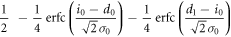
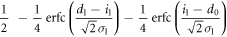
The conditional probability that Bob creates bit 0 when Alice sends bit 0,  , is given by

where  is the complementary error function expressed as
  . On the other hand, the probability that Alice sends bit 0 is
  . Thus, the joint probability that Alice's bit 0 coincides with Bob's bit 0,
  , is given by

The other joint probabilities are similarly derived, which are listed in table 1. By substituting these probabilities into (2), we obtain the mutual information between Alice and Bob.
Table 1. Joint probabilities between Alice and Bob.
| Alice's bit a | Bob's bit b | Joint probability 
|
|---|---|---|
| 0 | 0 |

|
| 0 | X |
|
| 0 | 1 |

|
| 1 | 0 |

|
| 1 | X |
|
| 1 | 1 |

|
For a highly secure key, the numbers of bits 0 and 1 should be equal. Thus, Bob's probabilities of creating bit 0 and bit 1 must be equal, that is
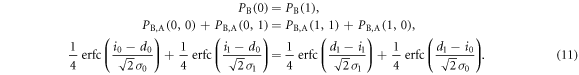
The second terms on both sides, which represent Bob's error probabilities, are usually much smaller than the first terms. Therefore, the above equation can be approximated as

From this equation, we have

Alice and Bob choose the system parameters of I0, δ, and d0 so as to achieve the largest final key rate under the above condition.
3.3. Mutual information in BSA
In fiber transmission systems, the signal power is attenuated in the fiber. Eve can eavesdrop using the lost signal power by inserting a beam splitter and replacing the fiber with a lossless line, as illustrated in figure 3. This eavesdropping method is called a BSA. In this subsection, we estimate the joint probability between Alice and Eve and that between Bob and Eve, and then, obtain the mutual information between them in the case of a BSA. In the following discussion, Eve is assumed to measure the signal light with an ideal direct detector, which has 100% quantum efficiency and causes no thermal noise. This assumption is made because the bit information is encoded into the light intensity (or the photon number) with an arbitrary phase, and thus, the use of an ideal direct detector (or a photon number detector) is the optimal strategy for Eve to measure the signal state.
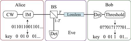
Figure 3. Beam-splitting attack. BS is a beam splitter with a transmittance T and a reflectance  . Lossless is a lossless channel. Eve detects signal with an ideal direct detector.
Download figure:
Standard image High-resolution image3.3.1. Joint probability between Alice and Eve
Figure 4 shows the distribution of Eve's measured light intensity. It has two peaks, corresponding to Alice's bits 0 and 1, respectively, that partially overlap because of quantum noise and optical classical noise. For this signal distribution, Eve sets a threshold dE between the two peaks, and creates bit 0 or 1 when the received signal is lower or higher than dE, respectively. When Alice launches the light intensity I0 into a fiber line with transmittance T, Eve's mean light intensity  and it's variance
  are given by


When Alice transmits the light intensity  , on the other hand, Eve's mean light intensity
  and it's variance
  are expressed as


With these parameters and the threshold dE, the joint probabilities between Alice and Eve are obtained using a procedure similar to that used in section 3.2. These probabilities are summarized in the table 2.

Figure 4. The distribution of Eve's received light intensity.
Download figure:
Standard image High-resolution imageTable 2. Joint probabilities between Alice and Eve for BSA.
| Alice's bit a | Eve's bit e | Joint probability 
|
|---|---|---|
| 0 | 0 |
![$\displaystyle \frac{1}{2}-\displaystyle \frac{1}{4}{\rm{erfc}}[\displaystyle \frac{{d}_{{\rm{E}}}-(1-T){I}_{0}}{\sqrt{2}{\sigma }_{{{\rm{E}}}_{0}}}]$](https://content.cld.iop.org/journals/1367-2630/18/1/013018/revision1/njpaa0d9fieqn36.gif)
|
| 0 | 1 |
![$\displaystyle \frac{1}{4}{\rm{erfc}}[\displaystyle \frac{{d}_{{\rm{E}}}-(1-T){I}_{0}}{\sqrt{2}{\sigma }_{{{\rm{E}}}_{0}}}]$](https://content.cld.iop.org/journals/1367-2630/18/1/013018/revision1/njpaa0d9fieqn37.gif)
|
| 1 | 0 |
![$\displaystyle \frac{1}{4}{\rm{erfc}}[\displaystyle \frac{(1-T){I}_{1}-{d}_{{\rm{E}}}}{\sqrt{2}{\sigma }_{{{\rm{E}}}_{1}}}]$](https://content.cld.iop.org/journals/1367-2630/18/1/013018/revision1/njpaa0d9fieqn38.gif)
|
| 1 | 1 |
![$\displaystyle \frac{1}{2}-\displaystyle \frac{1}{4}{\rm{erfc}}[\displaystyle \frac{(1-T){I}_{1}-{d}_{{\rm{E}}}}{\sqrt{2}{\sigma }_{{{\rm{E}}}_{1}}}]$](https://content.cld.iop.org/journals/1367-2630/18/1/013018/revision1/njpaa0d9fieqn39.gif)
|
To actually calculate the joint probability summarized in table 2, we need to know Eve's threshold dE, which is determined as follows. In judging Alice's bit, Eve sets a threshold at a value at which the tails of the two peaks corresponding to Alice's bits 0 and 1 intersect, as shown in figure 4. This condition is expressed as

From this equation, we obtain Eve's threshold as:

When  , (19) can be approximated as

3.3.2. Joint probability between Bob and Eve
In this subsection, we derive the joint probabilities between Bob and Eve. The deriving proceedure is somewhat different from that in the previous subsections, because the optical classical noise has a correlation between Bob and Eve. To take this correlation into account, we separately consider the probability densities caused by the classical noise and by the quantum noise.
When Alice sends bit 0, the p.d. of her classical light intensity IBS,  , is given by

which originates from the optical classical noise with a variance of  . In the above equation, IBS fluctuates because of the quantum noise, which has no correlation between the two beam-splitter outputs. Taking this into account, the conditional probability that Eve creates bit 0 from this signal intensity IBS is given by

where IE is Eve's received light intensity, and  is her quantum noise. On the other hand, the conditional probability that Bob creates bit 0 when Alice transmits IBS is given by

where iB is Bob's received current signal, and  is his current variance.
From (21)–(23), the joint probability  , that Bob's bit 0 coincides with Eve's bit 0 when Alice sends bit 0, is given by
By integrating over IBS and then transforming variables as  ,
,  ,
,  ,
,  , and
, and  , this joint probability is rewritten as
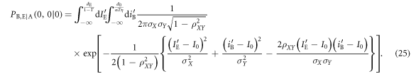
The joint probabilities of other bit combinations between the three parties (Alice, Bob, and Eve) can be similarly derived, the results of which are schematically shown in figure 5. The horizontal axis and vertical axis represent Bob's transformed signal,  , and Eve's transformed signal,
  , respectively. The six regions divided by the thresholds of Bob and Eve represent their bits. We obtain the other joint probabilities by integrating the distributions in corresponding regions, as in (25).

Figure 5. Bivariate normal distribution between Bob and Eve in BSA. The horizontal axis and the vertical axis represent Bob's transformed signal,  , and Eve's transformed signal,
  , respectively. The blue surface and green surface correspond to Alice's bit 0 and bit 1, respectively.
Download figure:
Standard image High-resolution imageApplying these results to (2), we can evaluate the mutual information.
3.4. Mutual information in IRA
In this subsection, we discuss the system performance (or mutual information) under an IRA. In this eavesdropping strategy, Eve intercepts and measures the signal on the transmission line, and then resends a fake signal to Bob based on the measured result. When Eve conducts this eavesdropping, Bob's error rate increases, because she cannot correctly measure and resend the signal; this increase in error rate can reveal the eavesdropping in principle. In practice, however, Bob's error rate fluctuates and Eve can partially perform the IRA with an optical switch, masking the eavesdropping-induced bit errors with the bit error rate fluctuation.
3.4.1. Key creation rate
Figure 6 shows the setup of the partial IRA, where Eve occasionally extracts the transmitted signal via an optical switch, and performs an IRA on the extracted signal. In this eavesdropping strategy, the switching rate r is an important parameter for Eve to efficiently steal the information. When she employs a high r value, she can measure a large fraction of the transmitted signal, but will induce a large error-rate at Bob, and therefore, has a high risk of being revealed. When employing a low r value, on the other hand, the risk of being revealed is low but the obtainable information amount is small. Thus, there is an optimum switching rate, which is discussed in the following.

Figure 6. Intercept-resend attack. Eve randomly switches the transmission line, and detects signal with an ideal direct detector. She resends a signal corresponding to the result from the detector.
Download figure:
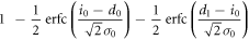
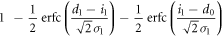
Standard image High-resolution imageFirst, we suppose that the information amount when Eve conducts full-IRA without an optical switch is given. Using this assumption, we discuss Eve's strategy for optimizing her switching ratio. The full-IRA information amount between Alice, Bob, and Eve is discussed in the next subsection. We assume that Bob creates a sifted key string of n bits, performs error-correction on it, and sets an error-rate threshold eth for it. When the error rate of the key string e, calculated from the error-corrected bits, is larger than eth, Bob discards the key, considering that Eve has eavesdropped on a large number of key bits. When the error-rate e is lower than eth, on the other hand, he assumes that the amount of leaked information is small, and therefore, performs privacy amplification on the corrected key.
Here, we discuss the error-rate distribution when the partial IRA is conducted, assuming that γ out of n bits of Bob's sifted key are intercepted and resent by Eve, and Bob's and Eve's original mean error-rates are eBob and eEve, respectively. Note that γ is a stochastic variable because whether an intercepted-resent signal exceeds the Bobs thresholds is probabilistic. Unintercepted  bits have a mean error-rate
  equal to eBob, while the mean error-rate of the intercepted-resent γ bits is
  . Because these probabilities are independent of each other, the p.d. of the error-rate in intercepted-resent γ bits, pIR(x), and that of the untouched
  bits, puIR(y), respectively, follow binomial distributions. With Gaussian approximation, they are given by


where 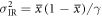 and
and 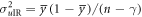 . The total error rate of n bits,
 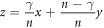 , is a linear combination of x and y. Thus, the p.d. of the total error rate, perror(z), is given by

where  ,
,  , and
, and  .
.
Next, we estimate Eve's net amount of eavesdropping information, RnetE, which is determined by two factors: the information amount that Eve obtains from the intercepted signal and the probability that Bob does not discard a sifted key. Denoting  as the information amount that Eve obtains from an intercepted signal, the net eavesdropping information amount when γ bits out of n bits of the sifted key are intercept-resent bits is given by

where 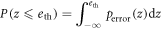 is the probability of Bob employing a sifted key. In the above expression, γ is a stochastic variable. Assuming that γ follows a binomial distribution with Gaussian approximation determined by the switching rate r, we obtain the net eavesdropping information amount, RnetE, as

where  is the variance of
  . It is efficient for Eve to maximize the net eavesdropping information amount, RnetE, and Alice and Bob conduct privacy amplification assuming the maximized RnetE.
The mutual information between Alice and Bob, on the other hand, is determined by Bob's error-rate and the probability that he discards a sifted key because of its large error-rate. Denoting the information amount shared between Alice and Bob without discarding as  , the net information amount between them, RnetAB, is given by

Therefore, the net final key creation rate on IRA,  , is given by

3.4.2. Joint probabilities in IRA
The previous subsection derives the final key creation rate, assuming that Eve's information amount  and the mutual information amount between Alice and Bob
  are given. In this subsection, we discuss these parameters. In IRA, Eve measures all of Alice's signal in the intercepting stage. Thus, the intensity variance of Eve's received signal when Alice sends bit 0,
  , is given by

The variance when Alice sends bit 1 is similarly determined. Then, the joint probabilities between Alice and Eve in IRA are obtained using the same procedure as in section 3.3.1, the results of which are summarized in table 3. Using these joint probabilities, we can estimate  .
.
Table 3. Joint probabilities between Alice and Eve for IRA.
| Alice's bit a | Eve's bit e | Joint probability 
|
|---|---|---|
| 0 | 0 |

|
| 0 | 1 |

|
| 1 | 0 |

|
| 1 | 1 |

|
Regarding Eve as a transmitter, we can estimate the conditional probabilities of Bob's bits. To deceive Bob, Eve resends a fake signal with the same properties as Alice's signal. For such signals, the probabilities of Bob's bits when Eve resends bit 0 or 1 are the same as those when Alice sends bit 0 or 1, which are summarized in table 4.
Table 4. Conditional probabilities between Eve and Bob for IRA.
| Eve's bit a | Bob's bit b | Conditional probability 
|
|---|---|---|
| 0 | 0 |

|
| 0 | X |
|
| 0 | 1 |

|
| 1 | 0 |

|
| 1 | X |
|
| 1 | 1 |

|
Here, however, there is a difference between Alice and Eve in their bit creation probabilities. Eve's bit creation probabilities can be estimated from the joint probabilities between Alice and Eve that are summarized in table 3. Taking these into account, a joint probability between Eve and Bob in IRA,  , is obtained as

The other joint probabilities are similarly obtained. From these joint probabilities between Eve and Bob, we obtain  , which was given a temporary value in the previous subsection.
The mutual information between Alice and Bob in IRA,  , is separable into those with and without Eve's interception,
  and
and  , as
, as

 is equal to the mutual information without Eve, which is discussed in section 3.1. On the other hand,
  is evaluated based on the joint probabilities between Alice and Bob via Eve. These values are obtained from the joint probabilities between Alice and Eve summarized in table 3 and Bob's bit probabilities for Eve's bits are summarized in table 4, as
Futhermore, we can obtain the error-rates, eBob and eEve, from these joint probabilities. From table 1, Bob's original error-rate, eBob, is given by

Similarly, Eve's error-rate, eEve, is estimated from table 3.
4. Simulations and discussion
Based on the above discussions, we simulated the system performance of the present scheme for BSA or IRA.
For the simulations, we first experimentally measured the proportionality constants for noise, a, b, and c, in (4), using the setup shown in figure 7. A continuous lightwave generated from a DFB-LD module (NTT Electronics, NLK1551HSC) was passed through a variable attenuator, and incident to an optical 3 dB coupler, the outputs of which were connected to an optical power meter and an optical receiver module (Sevensix Inc., SSR002), respectively. The receiver was composed of a PIN photodiode and a transimpedance amplifier (TIA) with a 1.2 kΩ transimpedance. The received signal was amplified, and its noise power was measured by a spectrum analyzer. We measured the noise power in a frequency range from 500 MHz to 10 GHz for various optical power levels coupled to the receiver. Besides, the quantum efficiency of the receiver was measured as η = 0.62. Figure 8 plots the measured noise power, as a function of the optical received power, by crosses. Also shown by the solid line in the same figure is a fitting curve of N(I) given by

where I is the received optical power,  is the TIA current gain,
  is the band-width in this measurement, and a, b, and c are constants. From this fitting curve, we evaluated the proportional constants as
  /Hz,
/Hz,  W Hz−1, and
  /Hz. These values would be used in our simulations.

Figure 7. Experimental setup to obtain the noise proportionality constants. CW is a continuous wave laser. VATT is an optical variable attenuator. OPM is an optical power meter. Det is an optical receiver module. Amp is an electrical amplifier. Spectrum analyzer is an electrical spectrum analyzer.
Download figure:
Standard image High-resolution image
Figure 8. Measured current noise power. Crosses are measured data and solid line is a fitting curve of N(I) given by (38).
Download figure:
Standard image High-resolution imageOther parameter values used in the simulations are as follows. The bandwidth of the intensity modulation is B = 10 GHz and the maximum laser output power is 2 mW. The sifted key length n in IRA is assumed to be either 1 kbit or 1 Mbit for examining the effect of key length. Bob's error-rate eBob is assumed to be less than 0.15. The fiber transmission loss is 0.20 dB km−1. Alice's transmitted signal power I0, the modulation depth δ, Bob's bit creation threshold d0, and Bob's error-rate threshold eth were chosen so as to maximize the final key creation rate at each transmission length. The intercepting ratio r was chosen such that Eve obtained the highest net eavesdropping information  .
.
Figure 9 shows the final key creation rate Rf in bidirectionally error-correcting systems. The system performance under IRA largely depends on the sifted key length: a longer length results in a higher key creation rate. This is because a longer key-bit length makes the error-rate variance smaller, reducing Eve's probability to mask her IRA using error-rate fluctuation. Figure 9 indicates that BSA is much more powerful than IRA in our present scheme.

Figure 9. Final key creation rate for bidirectional error correction.
Download figure:
Standard image High-resolution imageFigure 10 shows the final key creation rate Rf in reverse reconciliation systems. Similar to in the above-described bidirectional system (figure 9), BSA is shown to be stronger than IRA. The possible QKD distance is longer than that in the bidirectional error-correcting system, and the achievable distance is approximately 90 km. Note that the final key creation rate estimated here assumes 100% error correction efficiency, thus the practical achievable distance would be shorter than this result. The 90 km achievable distance is moderate or short, compared to conventional single-photon-based QKD systems [8–11]. These results suggest that the present scheme is suitable for short- or middle-range QKD systems.

Figure 10. Final key creation rate for reverse reconciliation.
Download figure:
Standard image High-resolution imageFigure 11 shows the assumed intensity modulation depth δ, used in figures 9 and 10, that maximizes the final key creation rate for each eavesdropping method. δ ranges from approximately 0.5 to approximately 2%. This small modulation depth may be an issue in practical implementations. When the resolution of the intensity modulator is not sufficient to realize this preciseness of the modulation depth, the modulation depth fluctuates, resulting in a large proportional constant for classical noise, i.e., a in (4). Thus, the correlation between Eve and Bob increases, and the transmission distance decreases. Quantitative analysis on this issue will be required for practical implementation.

Figure 11. Intensity modulation depth δ for each eavesdropping method.
Download figure:
Standard image High-resolution image
5. Conclusion
We presented a novel CVQKD scheme employing intensity-modulation and simple direct-detection. We described the setup and the protocol of our QKD scheme, and then, analyzed and calculated its system performance for both BSAs and IRAs. The results showed that short- or middle-range QKD is achievable with our scheme. With the features of use of conventional intensity-modulation/direct-detection technologies, our scheme is suitable for small- or moderate-size networks such as LANs and MANs.