


Abstract
An all-Si photonic structure emulating the quantum-valley-Hall effect is proposed. We show that it acts as a photonic topological insulator (PTI), and that an interface between two such PTIs can support edge states that are free from scattering. The conservation of the valley degree of freedom enables efficient in- and out-coupling of light between the free space and the photonic structure. The topological protection of the edge waves can be utilized for designing arrays of resonant time-delay photonic cavities that do not suffer from reflections and cross-talk.
Export citation and abstract BibTeX RIS
Introduction
The discovery of topological phases of light has been one of the most exciting developments in photonics [1–11] in the past decade. It followed the time-honored path of translating the concepts from condensed matter physics into the language of optical sciences, followed by developing novel applications based on those concepts. Photonic topological insulators (PTI) can be viewed as the extension of topological insulators [12–20] into the realm of optics. One potential application of PTIs is to utilize the reflections-free propagation of topologically protected edge waves (TPEWs) that exist either at the PTI's edge [3–5] or at the interface between two different PTIs [6, 7, 10] for developing robust optical delay lines for large-scale photonic integrations.
Specific implementations of PTIs vary considerably, and can utilize large coupled optical resonators [3, 4], wavelength-scale photonic structures [1, 2, 10, 21], or metacrystals [6]. To date, most of the wavelength and sub-wavelength scale PTI concepts utilized metals. For example, metallic metamaterials comprised of split-ring resonators [6] and meta-waveguides comprised of an array of metal rods attached to one of the two confining metal plates [10, 21] have been used to emulate the binary spin degrees of freedom (DOF) by ensuring that the two polarization states of light, the transverse electric (TE) and transverse magnetic (TM) modes, propagate with the same speed. This, property, known as spin-degeneracy [6, 7], is challenging to achieve without using metals. Avoiding metals is crucial if the spectral range of sub-wavelength PTI is going to be extended beyond the THz/mid-infrared portions of the electromagnetic spectrum.
In this letter we demonstrate that an all-dielectric PTI can be developed by relying on a binary degree of freedom other than the spin. In designing the structure, we borrow the concept of the valley DOF from a rising field of valleytronics [22–27]. It has been theoretically shown [22–24] that the valley DOF in any graphene-like material behaves as a spin-like binary DOF. Specifically, the angular rotation of the electron wavefunction in the K or K' valleys of the band structure generates an intrinsic magnetic moment [23] analogous to that produced by the electron spin. This similarity between the valley and spin DOF enables the quantum-valley Hall (QVH) effect [27] analogous to the quantum-spin Hall effect [12]. The latter effect manifests itself in the existence of the spin-locked (chiral) edge states at the graphene's edge which are immune to scattering by non-magnetic defects. Similarly, the QVH effect manifests itself in valley-locked chiral edge states that exist at the domain walls between, for example, AB and BA-stacked electrically biased bilayer graphene [25–27].
The analogy between the two effects and the utility of the valley DOF can be appreciated by comparing the mechanisms of topological protection in these two cases. In QSH effect, at the Fermi level in the topological band gap, two edge states propagating in the opposite directions are locked to the spin DOF. As a consequence, a non-magnetic defect is unable to scatter a forward propagating edge state back (or vice versa) because no spin-flipping can take place during the scattering process. Similarly, for QVH effect, there exists a broad class of defects defined by their symmetry that act as 'non-magnetic' perturbations because they do not cause inter-valley scattering. Therefore, the edge states in the topological band gap are topological protected against backscattering in the presence of such defects.
Specifically, we show that the QVH effect can be emulated in an all-Si hexagonal photonic crystal with broken inversion symmetry (analogous to an AB-stacked electrically biased bilayer graphene) as shown in the inset of figure 1(b). It thereby leads to the suppression of the inter-valley scattering and the topological protection in such photonic systems under a broad class of photonic lattice perturbations. The valley DOF utilized in QVH effect is much easier to realize in photonics than the spin DOF. For example, earlier work employed TE and TM polarizations to emulate the spin DOF [6, 7, 10]. A single TM polarization was employed for constructing the spin DOF in a recent all-dielectric design, but at the expense of using an enlarged (triple-sized) unit cell [28]. In contrast, as we show in this work, just a single (TE) polarization of the photonic modes is needed for constructing the valley DOF in a fairly simple photonic structure shown in figure 1(b), where, by breaking the inversion symmetry of a unit cell, a controllable bandgap separating different topological phases of propagating light can be achieved.

Figure 1. Photonic band structure and electromagnetic modes of unperturbed and perturbed photonic structures. (a) The photonic band structure of an unperturbed all-Si 'photonic graphene' . Red lines: the relevant photonic bands forming a Dirac points at the  point. Insets: the unit cell with a round Si rod in vacuum (left) and the first Brillouin zone (right). (b) The photonic band structure of a perturbed Si-PhC as a QVH-PTI. Inset: triangular Si rod. (c) Unperturbed and (d) perturbed field profiles of the LCP and RCP states at the k point of a photonic graphene. Color:
  Arrows: power flux. Parameters of the QVH-PTI:


 where
where  is the lattice constant.
Download figure:
Standard image High-resolution imageWe also demonstrate that an interface between two such quantum-valley-Hall (QVH) PTIs with different symmetry-breaking geometries (see figures 2(a) and (b) for a typical example) supports highly-confined TPEWs. Topological protection against backscattering enables near-perfect out-coupling efficiency of TPEWs into vacuum as illustrated in figures 3(a) and (b) despite their tight spatial confinement. Moreover, TPEWs can be used to confine light waves circulating inside an arbitrarily shaped/sized embedded defects exemplified by a quasi-random cavity shown in figure 4(a). When placed in close proximity of a domain wall separating two different QVH-PTIs, such defect cavities can act as robust reflection-free optical delay lines.

Figure 2. Topologically protected edge waves (TPEW) along zigzag interfaces between two QVH-PTI claddings. (a) The super-cell used for COMSOL simulations: single cell along the propagation x-direction and 20 cells on each side of the interface. The field profile of the TPEW at the  point for the positive-type interface with group velocity being positive(negative). (b) Same as (a) but with the negative-type interface in which the triangular rods are flipped by 180°. Color:
  (c) The photonic band structure of the structures in (a) and (b). Gray-shaded region: bulk modes; solid/dashed blue lines: TPEWs in (a)/(b).
Download figure:
Standard image High-resolution image
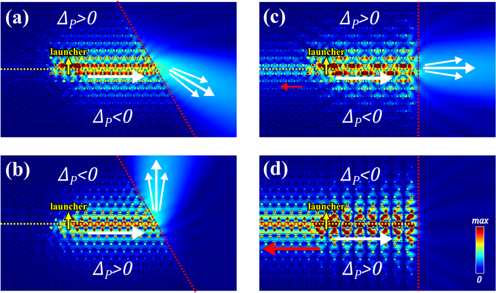
Figure 3. Out-coupling of TPEWs into vacuum with different terminations. (a), (b) Zigzag terminations of the QVH-PTI waveguide. (a), (b) Efficient out-coupling for zigzag terminations of the structures shown in figures 2(a) and (b). (c), (d) Same as (a) and (b) but with armchair terminations. White arrows: transmitted waves, red arrows: reflected waves. Color:  Yellow- and red-dotted lines highlight the guiding interface and the termination, respectively.
Download figure:
Standard image High-resolution image
Figure 4. Robust delay lines using whispering-gallery-type resonators with an arbitrary shape. (a) Schematic of the isolated random two-phase cavity (red triangles: inside
  matrix). The blue-dashed line outlines the interface between the two phases. (b) Cavity in (a) is coupled to a QVH-PTI bus waveguide. White arrows: direction of the power flow. Color:
  Yellow- and red-dotted lines: guiding interface and the termination into vacuum. (c) Delay time
  and transmission
  The gray-shaded region are outside the bandgap of QVH-PTIs; the smaller middle spectra are the zoom-in of the dashed-line box. The blue-dashed line marks the 90% transmission to guide eyes. The red arrow indicates the frequency where the field profiles of (b) is plotted. Parameters: same as in figure 1(b).
Download figure:
Standard image High-resolution image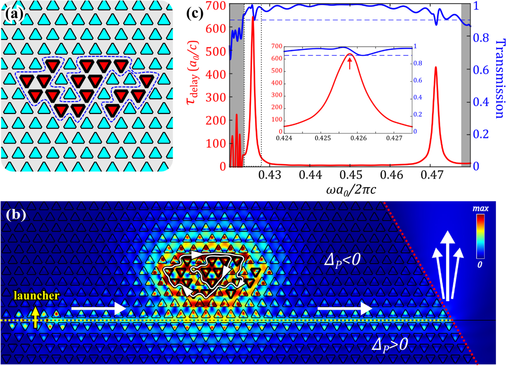
Design of a valley Hall all-dielectric PTI
The starting point of the design is an unperturbed photonic graphene [29] comprised of a two-dimensional hexagonal lattice of circular Si rods with lattice constant a0. The unit cell of the photonic graphene is shown in the inset of figure 1(a). As in any uniaxial structure, the eigenmodes propagating in the (x, y) plane can be classified as TE  and TM
  Here we restrict the discussion to the TE modes; the representative field component can be thereby expanded with Bloch ansatz:

where the  index refers to lower (upper) propagation bands, and
  is the normalized field profiles chosen to be periodic in the
  plane. The normalized electric field components of the modes can be obtained from equation (1) from the following relation:
 ![${{\boldsymbol{e}}}_{\perp }^{n,{{\boldsymbol{k}}}_{\perp }}({{\boldsymbol{r}}}_{\perp })=\frac{{\rm{i}}c}{{\omega }_{n}{\epsilon }({{\boldsymbol{r}}}_{\perp })}[({\rm{i}}{k}_{y}+{\partial }_{y}){h}_{z}^{n,{{\boldsymbol{k}}}_{\perp }};-({\rm{i}}{k}_{x}+{\partial }_{x}){h}_{z}^{n,{{\boldsymbol{k}}}_{\perp }}].$](https://content.cld.iop.org/journals/1367-2630/18/2/025012/revision3/njpaa144fieqn21.gif) The eigenfrequencies
The eigenfrequencies  of the relevant two modes are calculated using COMSOL Multiphysics as shown in figure 1(a) and highlighted in red, where
  belongs to the first Brillouin zone (BZ). The boundaries and high symmetry points of the BZ are shown in the inset of figure 1(a).
The presence of  wave vector symmetry group of the hexagonal lattice [30] results in cone-like dispersion curves in the non-equivalent K and K' 'valleys' [22–24] of the BZ. The intersections of these cone-like dispersion curves at the K and K' points are known as the Dirac points; each of them is doubly-degenerate. This degeneracy at the Dirac frequency
  allows us to choose the orthonormal orbital basis of the right- or left-hand circular polarizations (RCP and LCP). The field profiles of the RCP and LCP modes for the unperturbed photonic graphene are shown in figure 1(c), and they are invariant under a
  rotation,
  along z-axis (see supplementary information for more details).
In order to investigate the topological aspect of the modes, an effective Hamiltonian description must be analytically derived, and the connection to the commonly known Hamiltonian of 2D topological materials must be established. This effective Hamiltonian  which is a function of the in-plane wavenumber, will be expressed in the basis of the RCP/LCP states in close proximity of the
  and
and  points of the BZ. Of course, such effective Hamiltonian is an approximation because it utilizes a small number of propagating eigenmodes of the photonic structure, and because its validity is justified only near the high symmetry points of the BZ. However, it serves two purposes: (a) qualitative explanation of the emergence of the bandgap due to the inversion symmetry breaking, and (b) calculation of the relevant topological invariants, known as the valley-Chern indices [31] in condensed matter physics. The existence of such non-vanishing topological indices are crucial for the existence of the TPEWs at an interface between two QVH-PTIs. The analytic calculation of
  in the presence of the inversion symmetry breaking deformation of a Si rod (exemplified by an inset in figure 1(b)) will be based on the first-order perturbation theory [32].
We start the analytic calculation by defining the corresponding expansion basis and the state vectors of the effective Hamiltonian. If the amplitudes of the RCP/LCP modes in the corresponding valleys are  and
and  respectively, then any eigenstate can be expressed as a state vector
 ![${{\bf{U}}}_{K(K^{\prime} )}=[{a}_{K(K^{\prime} )}^{R};{a}_{K(K^{\prime} )}^{L}].$](https://content.cld.iop.org/journals/1367-2630/18/2/025012/revision3/njpaa144fieqn34.gif) The degenerate orbital expansion basis
The degenerate orbital expansion basis ![${{\bf{U}}}_{R}=[1;\;0]$](https://content.cld.iop.org/journals/1367-2630/18/2/025012/revision3/njpaa144fieqn35.gif) and
and ![${{\bf{U}}}_{L}=[0;\;1]$](https://content.cld.iop.org/journals/1367-2630/18/2/025012/revision3/njpaa144fieqn36.gif) can be defined according to the symmetry property (invariance under
can be defined according to the symmetry property (invariance under  of the RCP and LCP fields which is maematically expressed as
  An extended state vector combining both valleys can be defined as
 ![${\boldsymbol{\Psi }}=[{{\bf{U}}}_{K};{\bf{T}}{{\bf{U}}}_{K^{\prime} }],$](https://content.cld.iop.org/journals/1367-2630/18/2/025012/revision3/njpaa144fieqn39.gif) where the transformation matrix
where the transformation matrix  swaps the RCP and LCP orbital states to follow the commonly used convention that pairs up the amplitudes of the modes (
 and
and  connected through the time-reversal transformation. The unperturbed Hamiltonian
  near the Dirac points in this basis can then be expressed [12] as

where  is the group velocity, and
  is the dtance from the Dirac points defined as
  for the
  and
and  points, respectively. The Pauli matrices
  and
and  act on the orbital and valley state vector, respectively,
  are the corresponding identity matrices, and
  is the shorthand for the Kronecker product.
Next we introduce the perturbation of a unit cell accomplished by the deformation of the Si rods. It has been shown [21] that any geometric perturbation that breaks the inversion (P)-symmetry yet preserves the  point symmetry does not couple the RCP and LCP modes. It means that the perturbation matrix (responsible for lifting the degeneracy of the RCP and LCP orbital states) is diagonalized:

The proportionality of  simply shows that the effect of the perturbation is the same for both valleys, and it is a consequence of the time-reversibility. An example of such a geometric perturbation is shown in figure 1(b). The corresponding field profiles after the perturbation are shown in figure 1(d). Together with equations (2) and (3), one can obtain the photonic band structure of the perturbed system by calculating the eigenfrequency,
  of the matrix equation
  where
where  The size of the bandgap
  is proportional to the perturbation strength
  which can be determined from the first-order perturbation theory [32]:

where  is the pertubated volume, and
  is the changing permittivity after perturbation (circular to triangular rod). The
  sign of
  depends on whether the vacuum region is replaced by Si or vice versa. It can be observed from figure 1(c) that the sign of
  depends on the orientation of the triangular rod. For example, the triangular rod with one of the three vertices pointing toward
  as shown in figure 1(b) has the most negative
  (indicating that
  whereas a triangular rod rotated by 180° has the largest positive
  (
( ).
).
Although the band structures and the eigenfrequencies  of the perturbed system with the opposite signs of
  are identical to each other, the topological indices of the propagating modes in these two photonic structures are not. The non-trivial topological property of the modes can be characterized by the non-vanishing valley-Chern indices [31],
  By definition [33],
 ![${C}^{(v)}={\int }_{{\rm{BZ}}(v)}{{\rm{d}}}^{2}\delta {\boldsymbol{k}}\;{[{{\rm{\nabla }}}_{\delta {\boldsymbol{k}}}\times {\boldsymbol{A}}(\delta {\boldsymbol{k}})]}_{z}/2\pi ,$](https://content.cld.iop.org/journals/1367-2630/18/2/025012/revision3/njpaa144fieqn73.gif) where
where  is the valley label, and
  is half of the BZ corresponding to
  for
for  respectively. The local Berry connection [34–36] is calculated as
  where
where  and
and  are projections onto the
  valley subspace of the full spinor
  as the eigenvector with the corresponding eigenfrequency below the bandgap. Using the effective Hamiltonian of equations (2) and (3), we calculated the non-vanishing valley-Chern indices to depend on the specific valley and on the sign of
  according to
  .
.
The ability to control the sign of  by simply rotating the triangular rods of a QVH-PTI allows one to create a topological cladding that supports topologically protected edge waves (TPEWs) [21] at the interface between two QVH-PTIs with opposite signs of
  According to the bulk-boundary correspondence [37], the difference between the number of forward-moving modes and the number of backward-moving modes equals the difference of the valley-Chern indices. For example, an interface along the zigzag direction shown in figure 2(a) has
  in the upper(lower) domain; consequently, there is a forward-moving TPEW at the
  point because
  and a backward-moving TPEW at the
  point because
  The dispersions of TPEW for such interfacing are calculated using COMSOL Multiphysics and shown in figure 2(c). According to the propagation direction of TPEWs, here we refer to the interfaces shown in figures 2(a) and (b) as 'positive-type' and 'negative-type', respectively. The TPEWs are strongly localized near the interface between PTIs with the opposite signs of
  on either side of the interface.
The most remarkable property of the TPEWs that can be observed from figure 2(c) is that, for a given valley, there is only one surface mode propagating in the direction that is 'locked' to the valley. Therefore, if no inter-valley scattering takes place, then a forward-propagating surface mode cannot back-scatter. This property of the surface modes is responsible for their topological protection. Below we discuss the physical origin of the suppression of inter-valley scattering along with two applications TPEWs can offer: (i) to reflections-free out-coupling into vacuum, and (ii) to designing topologically protected random cavities that can be utilized for time-delaying optical pulses.
Application: valley conservation at a zigzag termination of a PTI waveguide
Of course, TPEWs are not unique in their localization: a variety of guided modes can propagate in channels separating any two photonic crystals that have a bandgap around the desired wavelength. The advantage of using topological claddings which, in addition to having a bandgap, also possess different signs of the valley-Chern index, is that the resulting TPEWs cannot back-scatter as long as they stay within the same valley (i.e. there is no inter-valley scattering). Such topological protection presents an interesting opportunity for reflection-free out-coupling of the TPEWs into the vacuum region. The key to such efficient out-coupling is the absence of inter-valley scattering at the specific termination of the photonic structure. To anticipate the types of terminations that result in a vanishing inter-valley scattering, one needs to calculate the field overlap between two valleys' TPEWs. It turns out that the inter-valley field overlap vanishes under the so-called zigzag-type perturbations, but remains non-zero when the perturbation is armchair-type (see SI for detailed discussions). It is thereby expected that a TPEW cannot scatter into a different valley when encountering a termination which is along the zigzag [38] direction as shown in figures 3(a) and (b).
We used COMSOL simulations to demonstrate the perfect matching of TPEWs into vacuum. The setup shown in figures 3(a) and (b) consists of three in-line phase-matched point dipoles and used to launch forward-propagating TPEWs along the positive- and negative-type interfaces, respectively. We observe from figures 3(a) and (b) that the TPEWs are smoothly out-coupled into vacuum without any reflections. Notably, the direction of the outgoing beam into vacuum depends on the effective refractive indices of the QVH-PTI waveguides: the light launched into vacuum from a positive-type interface between two PTIs refracts according to the standard (positive-index) Snell's Law as shown in figure 3(a). On the other hand, the negative-type interface launches negatively-refracted light into vacuum as shown in figure 3(b). However, in both cases reflections are absent. Note that the time-reversal symmetry guarantees that perfect coupling into TPEWs from vacuum can be obtained by properly designing an optical beam impinging from the vacuum-side with its profile accurately matched to figures 3(a) and (b).
To verify that perfect out-coupling of TPEWs is indeed related to the conservation of the valley DOF, we have constructed an alternative termination of the QVH-PTI waveguide that does not suppress inter-valley scattering. Such armchair terminations are shown in figures 3(c) and (d) as red vertical lines. The reflection calculated using COMSOL simulations shown in figures 3(c) and (d) are  for the positive-index TPEWs and
  for the negative-index TPEWs. This example demonstrates that, in the absence of complete suppression of inter-valley scattering afforded by a zigzag interface, very strong reflection should be expected at an impedance-mismatched interfaces such as between a photonic crystal and vacuum.
It is worth to point out that although a TPEW is immune to the reflection from a sharp bend [10, 21] inside a PTI waveguide, the reflection-free feature is by no means guaranteed when a TPEW hits the edge of a PTI waveguide. Poor coupling between guided and free-space modes is a generic problem in the field of optical communications which can be generally formulated in terms of impedance mismatch between the waveguide and vacuum. This problem, however, can be overcome in a QVH-PTI waveguide by terminating the sample along a zigzag direction as shown in figures 3(a) and (b). Even though the vacuum does not have an appropriate valley DOF either, the inter-valley scattering does not take place because of the symmetry properties of a zigzag-type perturbation which results in a vanishing field overlap between the two TPEWs belonging to different (K and K') valleys.
Application: robust delay lines based on reflection-free random cavities
When two PTIs with the opposite signs of ΔP are embedded in each other, as shown in figure 4(a), multiple zigzag interfaces between the two phases emerge. Those interfaces can guide edge waves along multiple paths without back-scattering. Therefore, such a mixture of ΔP > 0 and ΔP < 0 phases becomes a resonant cavity when imbedded inside a PTI. The number of TPEW modes supported by a cavity depends its size, as well as on the relative abundance of the two phases. When such two-phase cavities are placed in close proximity of a bus waveguide comprised of a straight interface between two PTIs as shown in figure 2(b), the trapped TPEWs can weakly couple to the passing surface mode. Because of the suppression of inter-valley scattering, the two-phase cavity is directionally coupled to the bus waveguide. Therefore, one can envision a robust reflections-free delay line that relies on directional coupling for suppressing reflections. Unlike standard directional couplers that must be multiple wavelengths long to avoid back-scattering, the proposed topologically protected delay line can be rather compact.
The valley conservation or the suppression of the inter-valley scattering can be understood by calculating the field overlaps between the modes of two valleys. It has been shown [21] that within the perturbed volume of a single unit cell, the field overlaps of the modes belonging to different valleys vary between positive and negative values; advantageously, such variations tend to average out (see SI for details). Besides, the field overlap integrals in the neighboring cells also tends to cancel each other out. In fact, as demonstrated in the SI, a perturbation consisting of rotating three triangular rods in a row along any zigzag directions (zigzag-type perturbation) in the exact same way results in a perfect cancellation of the individual perturbations. Therefore, a perturbation with random rotations among cells results only a higher-order coupling: ![$O[{{\rm{\Delta }}}_{P}^{2}]$](https://content.cld.iop.org/journals/1367-2630/18/2/025012/revision3/njpaa144fieqn95.gif) (coming from non-zigzag-type perturbations) between two valley modes as opposed to the first-order coupling caused by
(coming from non-zigzag-type perturbations) between two valley modes as opposed to the first-order coupling caused by  perturbation (figure 1(b)) responsible for a topological bandgap:
  From this discussion, one can expect that the coupling strength between two valleys' modes from a random perturbation are considerably smaller than ΔP
.
From this discussion, one can expect that the coupling strength between two valleys' modes from a random perturbation are considerably smaller than ΔP
.
To confirm this conjecture, we perform an eigenfrequency simulation of a random cavity with its geometry shown in figure 4(a). Because of the unbroken time-reversal symmetry and the fact that two valleys' modes are one-to-one time-reversal partners, one expects that the discrete eigenmodes of such cavity with localized fields must all be doubly-degenerate if the inter-valley interaction is strictly zero. That implies that all eigenvalues must come as pairs, i.e.  where the superscript labels the pair. If any finite frequency splitting
  emerges, then it must be attributed to inter-valley scattering and reflect the coupling strength between the two valleys' modes. For a specific two-phase cavity shown in figure 4(a), we have calculated using COMSOL eigenvalue modeling that the resultant normalized eigenfrequencies are
  and
and  Note the near-perfect degeneracy of the modes in each of the pairs: the normalized frequency splitting in each of the mode pairs is very small compared with the topological bandgap, i.e.
  and
and  respectively. Therefore, a typical isolated two-phase cavity shown in figure 4(a) is indeed valley-preserving, and can be potentially used as a whispering-gallery-type resonator for a reflection-free optical delay line. As discussed earlier, when such a cavity is coupled to a propagating TPEW, it acts as a directionally coupled resonator. The transmission of a TPEW propagating past, and coupled to, such a resonator is spectrally flat near the resonance frequencies
  of the resonator. However, its phase undergoes rapid changes at
  because the propagating TPEW couples to the trapped TPEWs inside the two-phase cavity and, effectively, spends more time circulating inside the directionally coupled resonator .
An example of a two-phase topological cavity (emulating a directionally coupled resonator) coupled to a TPEW-supporting straight interface between two PTIs (emulating a bus waveguide) is shown in figure 4(b), where the cavity is separated by two rows from the straight interface between PTIs. If the coupling rate  between the bus waveguide and the directionally coupled resonator greatly exceeds the inter-valley coupling rate
  inside the cavity, and this external coupling does not significantly increase
  then the above mentioned unity transmission
  and the rapid change of the phase
  of the transmitted signal with the complex-valued coefficient
  are both anticipated. The results of a COMSOL simulation presented in figure 4(c) confirm these conjectures. The transmission is mostly near unity and above
  across the bandgap frequency range. The delay time
  where
where  and
and  are calculated with and without the resonant cavity, is normalized to
  and plotted in figure 4(c) for the entire bandgap frequency range. The peak of time delay as large as
  from a two-phase cavity that is only 8 × 4 rows in size, without compromising high transmission, are predicted by our simulation.
The zoom-in of  in the spectral vicinity of
  plotted in the inset of figure 4(c) is used to estimate
  From the linewidth of the resonance, the coupling rate between the waveguide and the cavity is estimated as
  thus validating the above
  assumption. The effective optical length of the cavity at the resonance frequency
  can also be estimated from as
  Finally, high transmission
  for all frequencies across the resonance indicates that the inter-valley scattering indeed remains weak, thus preventing reflections even for a high-Q (
 time-delay line.
While it is too early to predict the full potential of such topologically-protected random cavities, below we offer some arguments that may set such cavities apart from the standard directionally coupled resonators used, for example, in constructing ultra-compact optical buffers and delay lines [39]. One key property of a QVH-PTI random cavity is that it confines the circulating TPEWs inside its entire area A. Therefore, the number of modes in the cavity scales as N ∼ A. The implication of this scaling is that the mode density of a random cavity in a given area is larger than a traditional Si-ring whispering-gallery resonator. In the latter, the modes' number scaling is  because light is guided along the ring's circumference while leaving the inner area unutilized. This unfavorable scaling leads to the increase of the footprint of the device when one attempts to increase the time-delay bandwidth by using a series of ring resonators with different diameters.
To understand how a random cavity can alleviate this challenge, one might envision using a spaced sequence of random cavities of the same size but different from each other in the way the 'flipped' (i.e.  triangular rods are embedded in the
  photonic matrix. Inside each cavity, one half of the rods can be randomly flipped to support a certain number of cavity eigenmodes. The neighboring cavity would then have a different combination of the flipped rods, and support the same number of modes but with different eigenfrequencies. By using multiple combination of the flipped rods and stacking such random cavities in a sequence, the entire bandgap region would be spanned by the isolated time-delay peaks shown in figure 4(c), thereby broadening the operational bandwidth.
In conclusion, we have designed a new PTI analogous to the QVH effect using all-dielectric photonic crystal. The principle of valley conservation enables QVH-PTIs to be used for reflection-free guiding along arbitrary paths and for robust optical delays with random cavities. The fact that only a single TE polarization is required for constructing the valley DOF greatly releases the previous design restriction demanding to use both TE and TM polarization [6, 7, 10, 21]. The underlying physics responsible for the valley conservation under zigzag-type perturbation gives the opportunity for highly efficient external excitation of topologically-protected edge waves from the vacuum to a QVH-PTI waveguide. For these reason, a QVH-PTI can potentially serve as an important component in optical communication and integrated Si-photonics.