


Abstract
Many modern and future particle accelerators employ high gradient superconducting RF (SRF) to generate beams of high energy, high intensity and high brightness for research in high energy and nuclear physics, basic energy sciences, etc. In this paper we report the record performance large-scale SRF system with average beam accelerating gradient matching the International Linear Collider (ILC) specification of 31.5 MV m−1. Design of the eight cavity 1.3 GHz SRF cryomodule, its performance without the beam and results of the system commissioning with high intensity electron beam at Fermilab Accelerator Science and Technology (FAST) facility are presented. We also briefly discuss opportunities for further beam studies and tests at FAST including those on even higher gradient and more efficient SRF acceleration, as well as exploration of the system performance with full ILC-type beam specifications.
Export citation and abstract BibTeX RIS

Original content from this work may be used under the terms of the Creative Commons Attribution 3.0 licence. Any further distribution of this work must maintain attribution to the author(s) and the title of the work, journal citation and DOI.
1. Introduction
Over the past three decades, since pioneering realizations at CEBAF at JLab, TRISTAN at KEK and LEP-II at CERN in 1980s, the science and technology of superconducting radio-frequency (SRF) beam acceleration have matured and tremendously advanced. Widespread employment of SRF to improve the performance of existing accelerators and construction of new facilities is mostly due to advantages of the technology such as extremely low RF losses in the cavity walls at cryogenic temperatures, high wall plug to beam power conversion efficiency, possibility of long beam pulse operating modes, reduced interaction of the beam with larger aperture cavities leading to low impedance for high current beams, and high accelerating gradient, Eacc [1–6]. Table 1 presents key parameters for major linear accelerators based on the pulsed SRF, such as the Spallation Neutron Source at ORNL [7], the European Spallation Source in Sweden [8], the 'Proton Improvement Plan—II' (PIP-II) linac at Fermilab [9], the European X-FEL at DESY [10], MARIE FEL at LANL [11] and the proposed International Linear Collider (ILC) in Japan [12]. The SRF system of a particle accelerator consists of many subsystems and components such as RF cavities, fundamental RF input power couplers, high-order modes (HOMs) dampers, frequency tuners, cryostats, high-and low-level RF (LLRF) systems, instrumentation, vacuum system, and cryogenics, and all that should be coupled to the rest of the accelerator complex (beam sources and absorbers, beam diagnostics and control, vacuum, collimation and radiation protection, safety, tunnel environment control and interlocks, etc). Because of the additional complexity, beam operations or realistic tests with beams are considered ultimate indicators of achievement. As an example, the SNS linac beam operation has shown some degradation of the SRF cavity gradients which are routinely at a level about 13 MV m−1 on average, that is below the design specification (though some cavities indeed are at or even above the 15.8 MV m−1 level) [7].
Table 1. Design parameters of large pulsed SRF accelerator facilities.
| Facility | Accelerating gradient, MV m−1 | RF frequency, MHz | Repetition rate, Hz | Beam pulse length, ms |
|---|---|---|---|---|
| SNS | 15.8 | 805 (β = 0.81) | 60 | 0.7 |
| ESSa | 19.9 | 704 (β = 0.86) | 14 | 2.86 |
| PIP-IIa | 18.8 | 650 (β = 0.92) | 20 | 0.54 |
| X-FEL | 23.6 | 1300 | 10 | 0.65 |
| MARIEb | 31.5 | 1300 | 10 | 0.1 |
| ILCb | 31.5 | 1300 | 5 | 0.73 |
The ILC is one of the most complex accelerator projects ever considered and designed [12]. Each of the two ILC linacs will accelerate electrons or positrons from 15 GeV to maximum 250 GeV through 7, 332 9-cell 1.3 GHz SRF cavities, about 32 MeV per cavity. The cavities operate at 2 °K and are grouped into cryomodules, each approximately 12.6 m long, of two types with either eight or nine cavities in them. The beam energy gain in the 8-cavity cryomodule thus needs to be 32·8 = 256 MeV. To meet such a specification with 1.5% energy overhead, each 1.038 m long cavity should, on average, achieve a 31.5 MV m−1 accelerating gradient with an operationally acceptable spread of ±20%. It is of utmost importance to provide a highly reproducible and stable beam thus a powerful and flexible control system is needed for precision regulation of the RF fields inside the accelerating cavities.
The so-called 'S1-Global collaborative project' [13] was set up by the ILC Global Design Group to demonstrate achievement of a 31.5 MV m−1 gradient in a cavity string in one 1.3 GHz SRF cryomodule and perform a realistic system test with high current beam acceleration. Even getting the required average gradient without a beam, with RF only in a single cryomodule test stand was found to be formidable task [14], which was finally achieved at Fermilab [15]. Beam acceleration by the ILC/TESLA-type 1.3 GHz SRF cryomodules was first demonstrated at the FLASH facility at DESY with average gain per eight cavity cryomodule of 150–180 MeV initially and 200–240 MeV with an X-FEL type cryomodule [16], still below the ILC specification. Recent beam commissioning of the European X-FEL has shown that a few of about 100 cryomodules can achieve 27.2 MV m−1 gradients [17, 18], well above the X-FEL specification but short of the ILC goal of 256 MeV per SRF cryomodule. In this paper, we report for the first time a record high gradient SRF beam acceleration which meets the ILC requirement.
Fermilab has built an ILC-type cryomodule RFCA002 (CM2) which is comprised of eight 1.3 GHz cavities. The cavities were tested in vertical and horizontal test stands (HTS) at Jefferson Lab and Fermilab and all reached gradients in the range 33–41 MV m−1 before quenching [15]. The assembled CM2 was installed at the Fermilab Accelerator Science and Technology (FAST) facility [19] which houses the necessary 2K cryogenics and RF infrastructure for high power and beam testing, as shown in figure 1.

Figure 1. The 1.3 GHz SRF cryomodule (CM2) installed in the FAST/IOTA facility (courtesy: Fermilab).
Download figure:
Standard image High-resolution imageFAST consists of the Integrable Optics Test Accelerator (IOTA) ring, capable of operating with 150–300 MeV/c electrons and 70 MeV/c protons and its two injectors which includes the 1.3 GHz SRF electron linac—see figure 2. The facility is being built to host the accelerator R&D program towards multi-MW beams and experimental tests of novel techniques for high-current beam accelerators. Beam commissioning of the CM2 cryomodule and attainment of the ILC beam acceleration gradients took place in October–November 2017.
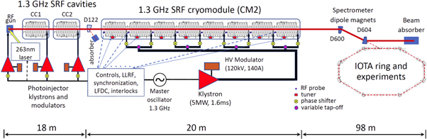
Figure 2. Schematic layout of the FAST/IOTA facility (not in scale).
Download figure:
Standard image High-resolution imageIn section 2 of this article we briefly present the design of the eight cavity 1.3 GHz SRF cryomodule, its performance without beam and novel technologies developed to stabilize the frequency, amplitude and phase of each cavity within tight specifications needed for the ILC-type beam acceleration. Results of the system commissioning with a high intensity electron beam at FAST are presented in section 3. Finally, we discuss further beam studies of efficient beam SRF acceleration and opportunities to achieve even higher beam accelerating gradients.
2. SRF cryomodule: design and performance
2.1. SRF cavities
The 1.3 GHz SRF accelerating cavities were originally developed in the context of the TESLA linear-collider project [20] and were included in the baseline design of the ILC [21]. Such a cavity, as depicted in figure 3, is a 9-cell standing-wave accelerating structure operating in the TM010;π mode. Total cavity flange-to-flange length is 1.247 m, while the active length (weighted with electric field) is 1.038 m. The cavity operates at 2 K with a design average acceleration gradient Eacc = 31.5 MV m−1 and quality factor Q0 ≥ 0.8×10¹⁰. Each cavity has two end group sections—one with a port for coupling RF power from the power source into the structure, and the other with a port for a field sampling probe used to determine and control the accelerating gradient. Each of these ports accepts an electric field antenna required for qualification and operation. In the process of building a cryomodule, these cavity structures are cleaned/processed, tested and dressed. Dressing involves welding a helium jacket around the cavity for cooling, attaching the tuner assembly including both coarse and fine tuners for adjusting the frequency of the structure, magnetic shielding to minimize the cavity losses, a variable fundamental power coupler for powering the cavity, an electric field sampling antenna and two HOM electric field antennas. Eight of these dressed cavities are connected into a string and are a subcomponent of a 12.6 m long superconducting cryomodule.

Figure 3. The baseline ILC cavity package ('dressed cavity'), titanium helium tank is shown as transparent for a view of the 9-cell niobium RF cavity inside. Reproduced with permission from [21].
Download figure:
Standard image High-resolution imageEach cavity is equipped with a so called 'blade tuner' system that transforms azimuthal rotation into longitudinal motion and changes the length of a cavity with it. The tuner allows both slow mechanical adjustment of the frequency of the cavity to bring it on resonance (static tuning) and a fast 'pulsed' adjustment using a piezo system to dynamically compensate Lorentz force detuning during the RF pulse. The tuning range of the cavity resonant frequency is of order 1 kHz.
2.2. SRF cryomodule
The SRF cryomodule, CM2, installed in the FAST facility is the second of two ILC-style 8-cavity cryomodules built at Fermilab. The cryogenic infrastructure of the facility allows 2 K superfluid helium cooling of the cryomodule [22]. All cavities were fabricated in industry and extensively tested cold prior to assembly into the cryomodule. While the first cryomodule was assembled by Fermilab staff with oversight by collaborators, parts were provided as a 'kit' by DESY, CM2 was largely assembled by Fermilab with parts also obtained by Fermilab. A single 5 MW peak 1.3 GHz klystron provides the necessary power to drive the cryomodule. A waveguide distribution system provided by SLAC National Accelerator Laboratory [23] is attached to the cryomodule fundamental power couplers and splits the incoming power amongst the eight cavities. The low-level RF drive system was developed based on previous systems for SRF test beds and includes provision for both amplitude and phase feedback control within the ILC specifications. Figure 4 compares the gradient performance of all cavities. Vertical and horizontal tests are conducted on bare single cavities first and then after dressing, respectively. At FAST single cavity tests were first carried out on each cavity individually, being driven by the RF source, and finally as a unit. Single cavity testing allowed the entire available RF power to be delivered to a single cavity while 'unit' tests necessarily limit the peak RF power available to a single cavity to a maximum of 1/8 of the total output of the klystron.

Figure 4. Measured maximum accelerating gradients in all eight SRF cavities of CM2. The RF pulse has 0.6 ms filling time and 1.0 ms flat-top.
Download figure:
Standard image High-resolution imageCM2 has now been operated for two extended operations periods—initial commissioning (without beam) from June 2013 through August 2015 and most recently for re-commissioning followed by beam operation beginning in July 2017 through November 2017. The main activities and accomplishments of the first run are previously described [15, 24].
Table 2 summarizes the peak gradients achieved and measured cavities' quality factors Q0 at the design gradient, 5 Hz repetition rate, temperature of 2 K and 1.57 ms long RF pulse length with 0.97 ms flat-top. Most of the resonators are demonstrated to operate above 32 MV m−1 and are limited at that point either by quench or available RF power. Cavity number 6 is the limiter and can operate only below 30 MV m−1 before quenching. This limit was demonstrated during both the first commissioning run—see purple line in figure 4 taken during no-beam test with the cavity off the resonance and without the regulation of the pulse flat-top-and verified during the most recent beam run. Since all eight cavities are now driven by a single RF source, individual cavity performance is limited by the available power and the amount going to the 'weakest' cavity. As conditions permit, re-orienting the RF distribution system would conceivably allow for higher performance of cavities based on their most recent demonstrated performance. At FAST the peak gradient was administratively limited to 31.5 MV m−1 during initial single cavity assessment in order to avoid any possible damage prior to all cavities reaching this level. This limit has since been raised to 35 MV m−1 and the gradients in all the cavities but one, #6, were limited by the available RF power. Though it was not critical for the CM2 operation at FAST, it is noteworthy that the majority of the cavities had measured quality factors Q0 above the ILC Technical Design Report [12] specification of 0.8×10¹⁰.
Table 2. Peak CM2 cavity gradients and quality factors. Total available accelerating voltage is 267.9 MV, and the average gradient of 32.2 MV m−1 (2015 measurements). Gradient measurements uncertainty is 0.5 MV m−1, accuracy of the quality factor measurements is better than 10%.
| Cavity No. | Eacc (MV m−1) 2013–15 | Eacc (MV m−1) 2017 | Q0/1010 at 31.5 MV m−1 |
|---|---|---|---|
| 1 | 32.3 | 31.7 | 0.87 |
| 2 | 31.8 | 31.7 | 1.41 |
| 3 | ≥33 | 31.6 | 1.25 |
| 4 | ≥33 | 31 | 0.88 |
| 5 | ≥33 | 31.7 | 0.85 |
| 6 | 29.8 | 30.5 | 0.64 |
| 7 | ≥33 | 32.3 | 0.57 |
| 8 | 32.2 | 31.2 | 0.76 |
| Sum voltage (MV) | 267.9 | 261.2 |
2.3. CM2 performance during beam tests
During the most recent test run in 2017 the commissioning protocol established previously was used albeit abbreviated: the klystron output remained oriented to drive all cavities simultaneously. This included a period of warm coupler conditioning followed by cool down, moving the cavities on resonance, on resonance conditioning, power calibrations, and finally peak gradient determination. The LLRF system was re-commissioned once cool down was completed and employed to move cavities on resonance. Feedback operation was re-established and gains were found to be virtually unchanged from previous operation. Similarly, adaptive feedforward compensation was rapidly re-deployed with minimal calibration time.
Perhaps not surprisingly, CM2 performance was found to be little changed even after a nearly 2 year hiatus at room temperature. Peak gradients, particularly that of cavity 6, were found to be essentially identical within normal error to that of before. The suite of radiation field emission detectors installed for initial commissioning was no longer available, but the remaining subset show indications of the same behavior as before. Q0 measurements have not been repeated.
In order to achieve the desired accelerating voltage despite cavity number 6's limitation, a few techniques were undertaken to maximize the sum voltage. These steps were done to cavity 6 in order to maintain its operating gradient below its quench limit while keeping the total RF voltage constant and included: slightly lowering its loaded quality factor QL, from 3.5×10⁶ to 3.1×10⁶ and de-tuning its resonant frequency by about 50 Hz off the drive frequency f = 1.3 GHz. Collectively the duty factor was lowered from 5 to 1 Hz and the flattop length reduced from the nominal 590 to 100 μs in order to reduce the average power/heating. Combined these steps allowed sufficient additional voltage to achieve the total CM2 electron energy gain above 250 MeV.
All in all, performance of CM2 during FAST beam operation has been quite reliable. Some activity in the RF power couplers, field emission and attendant vacuum, has been observed, but has not greatly affected beam stability.
2.4. Cavity control and stabilization: Lorentz force detuning (LFD) compensation and microphonics feedback
The ILC SRF cavities are susceptible to micro-scale mechanical deformations due to the relative thinness of their walls, 2.8 mm. Such deformations are induced by the force of the accelerating electromagnetic field on the walls as well as fluctuations in the pressure of the surrounding helium bath and microphonics induced by external noise sources. These mechanical deformations can change the resonant frequency of the cavity by Δf and lead to fluctuations of the phase and amplitude of the accelerating field beyond the ILC specifications of 0.35° and 0.07%, correspondingly [12]. For high-gradient, pulsed cavities operating in super-fluid helium, the dominant effect is the LFD due to the radiation pressure of the electromagnetic field during the RF pulse which deforms the cavity and pulls it off resonance proportionally to the square of accelerating field Eacc. For the ILC cavities the static detuning is approximately Δf ∼ −E2acc × 1.0 Hz/(MV/m)2 [25] but response to the pulsed force is complicated by excitation of mechanical vibrations, e.g. of the main resonant mode with about 200 Hz frequency. A reliable automated system to compensate for the LFD is needed, otherwise the ILC cavities would dynamically detune by several times the cavity's bandwidth of f/(2QL) ∼ 200 Hz and significant excess RF power would be required to maintain the accelerating gradient at the design level of 31.5 MV m−1.
The use of piezo actuators to compensate for LFD was pioneered at DESY but has since been adopted widely [26]. The DESY team employed the technique of exciting the piezo actuator with a half cycle of sine wave prior to the arrival of the RF pulse. The duration, delay and amplitude of the half sine wave are optimized manually by trial and error. This method became standard and is used by many groups [27]. While this standard approach can provide acceptable compensation for LFD, the mechanical response of individual cavities to the Lorentz force and to the piezo actuator can differ. Changes in cavity operating conditions, e.g., the changes in the gradient or bath pressure, can require corresponding changes in the compensating waveform. Operating multiple cavities for extended periods will require control systems that can automatically determine the best parameters for each cavity and adapt to changing operating conditions. Because the cavity detuning does not respond linearly to the changes in some parameters of the standard unipolar pulse, the adaptive capability that can be incorporated in LFD systems based on this standard approach may be limited.
The Fermilab team developed an innovative method to automatically determine an optimal piezo actuator waveform for each individual cavity based on an adaptive feed-forward algorithm [28]. As the first step, the cavity reaction to the piezo impulse is measured at a gradient of several MV m−1 below the maximum [29]. A series of low-amplitude unipolar 0.5 ms long drive pulses are sent to the actuator. The first pulse is timed to arrive some 10 ms in advance of the RF pulse. For each subsequent RF pulse, the delay between the piezo drive and the RF pulse is reduced by 0.5 ms until the piezo pulse follows the arrival of the RF pulse. The forward, probe and reflected RF waveforms are recorded at each delay and used to determine the detuning. The least squares algorithm is then used to find the combination of the delayed pulses that minimizes the frequency detuning from this data. Due to the nonlinear response of the system, the response needs to be measured over the range of the bias voltages on the piezo actuator. The voltage is thus stepped from pulse to pulse in small increments over the full range of the actuator and again the RF waveforms are recorded for each pulse. To measure the detuning due to the Lorentz force alone, the RF waveforms are recorded while no drive signal is sent to the piezo actuator. As a final step, the response matrix is used to calculate waveform (including bias) that will be applied to each cavity's piezo actuator. As operating conditions vary, the RF waveforms can be used to measure any residual detuning. The same response matrix can then be used to calculate the incremental waveform required to cancel that residual detuning.
Each dressed cavity, equipped with tuner, that was integrated into CM2, was tested first at horizontal test stand at maximum operating gradient in the range of 30–35 MV m−1 [30, 31]. A single-cavity LFD compensation system based on the Fermilab adaptive algorithm was deployed and actively used during the HTS testing [32]. A similar system extended to operate with eight cavities was successfully deployed to compensate the LFD in the CM2 cryomodule during its commissioning and, later, beam operation [33]. Figure 5(a) shows the detuning with and without compensation of a 9-cell elliptical cavity (TB9AES008) at the HTS during qualification tests. Because of limitation in the power of the HTS klystron without LFD compensation, cavities cannot be operated above Eacc = 27 MV m−1. The amplitude of the cavity's LFD during 0.5 ms RF pulse 'flat top' was almost 600 Hz. This implies that at 35 MV m−1 LFD without compensation could reach ∼1000 Hz. After turning on the adaptive LFD compensation system it was possible to raise the gradient on the cavity up to 35 MV m−1. The LFD compensation system suppressed the detuning to less than ±20 Hz during whole length of RF pulse. Figure 5(b) shows the piezo drive waveform used to compensate the LFD on this cavity.
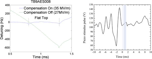
Figure 5. (a) left—effective Lorentz force detuning compensation in a 9-cell elliptical cavity number 1 over 0.5 ms flat-top at 35 MV m−1; (b) right—compensating piezo actuator waveform for the 1.3 GHz SRF cavity operating at Eacc = 35 MV m−1. Lightly shaded areas indicate the RF filling time period and the pulse flat-top depicted in figure 5(a).
Download figure:
Standard image High-resolution imageCavities can also be detuned by variations in the pressure of the helium bath or due to the microphonics. In addition to compensating for the rapid detuning induced by the Lorentz force, Fermilab's adaptive LFD algorithm monitors the cavity resonance frequency and adaptively adjusts the DC bias on the piezo actuator to stabilize the resonance frequency. The resonant frequency of the CM2 cavities over a period of several hours drift by up to 20 Hz when adaptive compensation is not active. When adaptive compensation is on the drift was suppressed to less than one Hz.
In summary, an adaptive LFD compensation system was successfully used to compensate for large (up to 1000 Hz) LFD in all 8 cavities in CM2 during commissioning and operation.
3. Record high gradient beam acceleration
The FAST beamline starts with a photocathode in a normal-conducting electron RF gun with 1.5-cell copper cavity operating at 1.3 GHz—see figure 2. A train of UV pulses from the drive laser strikes a Cs2Te-coated Mo cathode in the gun cavity resulting in a train of 4.5 MeV electron bunches with the bunch charge of up to 3.2 nCoulombs. The pulse train structure is selectable between a single pulse for the IOTA ring injection beam cycle (nominally 1 Hz) and up to a 1 ms long trains of 3000 bunches 333 ns apart and operates with repetition rate up to 5 Hz—see figure 6. The beam then passes through a short (∼1 m) low-energy diagnostic section before acceleration in two consecutive, individually powered superconducting RF accelerating structures referred to as the 'capture cavities', CC1 and CC2. Each capture cavity in its own cryostat is a 9-cell, 1.3 GHz Nb accelerating structure nominally cooled to 2 K. Following acceleration of up to maximum 52 MeV, the electron beam passes through the low-energy beam transport section, which includes steering and focusing elements, an optional chicane for bunch compression and beam manipulations, as well as a set of beam diagnostics instrumentation. It is then either directed into the low-energy absorber by the D122 dipole magnet or goes to the CM2, which further accelerates the beam to about 300 MeV beam. The high-energy beam is transported through a long beamline either to a high energy beam absorber or, in the future, into the IOTA ring injection section. Table 3 presents main parameters of the linac beam. The FAST beamline is well equipped with necessary types of beam diagnostics (see details in [19]): beam position monitors (BPMs), transverse profile monitors to measure beam size, resistive wall current monitors to measure beam current and loss monitors to measure beam losses and serve as the primary protection element in the machine protection system, while the beam energy is measured with the help of two spectrometer magnets D122 and D600.

Figure 6. Time structure of the IOTA/FAST electron injector beam. fmac is nominally 1–5 Hz, macropulse length is 0.1–1 ms, and fb is up to 3 MHz.
Download figure:
Standard image High-resolution imageTable 3. Main beam parameters of the IOTA/FAST electron injector.
| Parameter | FAST value |
|---|---|
| Beam energy to low-energy absorber | 20–52 MeV |
| Beam energy to high energy absorber | 100–300 MeV |
| Bunch charge, q | <10 fC–3.2 nC |
| Bunch frequency, fb | 0.5–9 MHz |
| Micropulse frequency, fmac | 1–5 Hz |
| Micropulse duration | <1 ms |
| Normalized emittance , εn (at 0.1 nC/bunch) | 0.6 mm mrad |
3.1. Cryomodule tuning
The optimization of RF phases between the gun, CC1 and CC2 is fairly simple, given that each has its own LLRF and high level RF systems, and maximizing the total energy gain is relatively easy with only three cavities. This is not the case for the CM2, in which 8 cavities are powered by one RF source and controlled by a common LLRF system, resulting in a vector sum of individual cavity energy gains Ui

that can rapidly become difficult to deconvolve as the LLRF control loop is forcing the vector sum to be equal to the set point and each relative phase and amplitude change could impact the remaining cavities. To find the optimal position for the individual cavity phase φi tuners, we employed a beam-loading-based tuning method. Beam loading is the effect of interaction of the beam current with the cavity. If the beam is accelerated by the cavity, it results in the increase of the beam energy and corresponding reduction of the energy of electro-magnetic fields stored in the cavity. Should the beam be out of phase with cavity's RF field it gets decelerated and therefore its energy is transferred to the cavity. For a short bunch with charge q, and the amplitude of the beam-induced wakefield in the cavity is given by [34]:

where (R/Q) is the cavity geometry dependent parameter of about 1000 Ohms for the ILC-type cavities, and ω is the frequency of the exited mode, 2π × 1.3 GHz in our case. Cavity monitors of the RF field thus would report the variation of the total RF voltage amplitude depending on relative phase of the RF and the beam Δφ = φi − φb. Adjustment of either the LLRF phase or the phase delay tuning motor could be used to shift the RF phase change corresponding to the beam loading. A phase shift over the complete RF cycle will include both maximum deceleration and maximum acceleration through the cavity, the latter corresponding to the maximum beam loading, as shown in figure 7 for cavity 1. Choosing to maximize the acceleration for all cavities to a LLRF phase set-point of 0, the phase delay tuning motor was adjusted to maximize the peak beam loading in the cavity.

Figure 7. Beam loading effect (reduction of the 1.3 GHz RF signal amplitude) in cavity 1 versus the RF phase.
Download figure:
Standard image High-resolution imageThis process was repeated for the remaining seven cavities and optimal phases were determined and set for all of them. Once all eight CM2 phase delay tuners were optimized, the beam was accelerated down the high energy beamline to the energy of 298.0 ± 3.4 MeV measured after the 15° dipole D600, which was used as the high energy spectrometer. There are two sources of errors in the energy measurement. First, it is the uncertainty in the beam angles before and after the dipole, measured by corresponding BPMs, which is estimated to be about 0.9% (2 mrad for the total bend angle of 15°). The second is the uncertainty of magnetic field calibration of the D600 magnet at the level of 0.7% rms. Stability of the energy past CM2 even with open-loop LLRF stabilization system was better than 0.1% rms, as derived from the beam position jitter in the BPM past D600.
The final beam energy is composed of the two parts gained in the low-energy section before CM2 and in CM2 itself. The first part was precisely measured with spectrometer magnet D122. That magnet was calibrated and had the NMR probe in it to measure actual magnetic field. Two pairs of BPMs are located immediately upstream and downstream of the D122 to measure the change of the beam trajectory angle. The resulting injector beam energy was found to be 42.9 ± 0.2 MeV for that particular run, therefore, the CM2 total acceleration was 255.1 ± 3.4 MeV.
3.2. Lattice tuning
Careful control of the beam size and trajectory is needed to assure lossless acceleration and transport of electron bunches from the gun to the high energy absorber, and, in the future, deliver suitable beam for the injection into the IOTA ring. Beam dynamics in a linear accelerator is defined by the initial conditions at a starting point and by the external perturbations in the downstream lattice. In a simplified form, the beam trajectory x(s) deviates from a perfect, e.g. straight, line, due to transverse angular kicks θk caused by imperfections, such as misalignment of magnets, RF cavities, etc in the preceding sections of the beamline [35]:

while the rms beam size varies as:

Here, β(s) is beta-function of the focusing lattice at the location of observation s—see figure 8—and βk are its value at the locations of the kicks, εn is the normalized beam emittance determined mostly by the electron source, θk is the dipole kick due to the kth imperfection, and the betatron oscillation phase φ(s) = ∫ds/β(s). After the initial manual tuning of propagation of the beam to the absorber, alternating steps of beam-based focusing lattice and trajectory corrections were made. The trajectory correction was aimed at minimizing beam offsets from the magnetic axis of quadrupoles. The analysis and correction of the focusing optics was done using the linear optics from closed orbit technique [36, 37]. Operationally important aspects of the focusing lattice tuning were optimization of the beam shape distortions at low energies (4.5–20 MeV) to minimize space-charge induced degradation of emittances at high bunch charge [38], careful control of the orbits through slightly misaligned capture cavities CC1 and CC2 and proper correction of the dispersion achromat in the dogleg formed by the two 15° dipoles (at around 110–120 m in figure 8) [39]. Figure 9 presents the beam profile images on the transverse profile monitor downstream of the D600 dipole before and after the beamline tuning showing a great deal of improvement resulting in loss-free transportation of optimal emittance beam.

Figure 8. Optical functions βx,y(s) along the 300 MeV IOTA/FAST electron injector linear accelerator. The origin is at the photo-injector cathode, and the beam ends at the high energy absorber. Presented are design values, measured beta-functions are commonly within ±10% from the design.
Download figure:
Standard image High-resolution image
Figure 9. High energy electron beam images from the beam after D600 as observed on the YAG:Ce crystal screen of the FAST transverse profile monitor: (left) before and (right) after the orbit correction and beamline focusing lattice tuning. Vertical and horizontal screen sizes are 20 mm.
Download figure:
Standard image High-resolution image
4. Conclusion
We have commissioned the 1.3 GHz superconducting RF linac at the FAST facility and have demonstrated the highest beam accelerating gradient ever achieved in large-scale SRF accelerators. Energy gain in the eight cavity 1.3 GHz SRF cryomodule CM2 exceeded 255 MeV and the average beam accelerating gradient matched the ILC specification of 31.5 MV m−1. Attainment of such record gradients is the result of more than a decade of R&D and was possible due to a) advances in the technology of the SRF cavity production, surface treatment and cryomodule assembly; (b) development of sophisticated LLRF and LFD compensation systems to control and stabilize cavities frequencies, gradients and phases at the very tight tolerances required for efficient beam acceleration; and (c) construction and commissioning of a modern electron photo-injector and high-energy beam transport line equipped with efficient beam diagnostics and control system to allow efficient tuning of the SRF accelerator parameters as well as beam trajectory, focusing optics and emittances.
FAST facility operation in 2017 consisted of two eight-hour shifts per day which allowed for active cryomodule and beamline commissioning and tuning in combination with several beam experiments carried out in collaboration with both external and internal research groups. These experiments included studies of effects of the HOM excited by the beam in CC1 and CC2 on the transverse beam emittance [40], tests of advanced beam diagnostics using synchrotron radiation from the D600 dipole [41], experimental verification of machine learning algorithms for optimization of the low-energy accelerator injector [42], investigation of the 4D beam phase space tomography [43], and innovative experiments on the round-to-flat beam transformations of magnetized high intensity electron beams [44, 45].
The achieved beam parameters—energy, intensity, stability and emittance—fully meet the specifications of the program of accelerator R&D at the IOTA ring toward intensity frontier beams [19, 46]. Besides this main goal, we plan to continue exploration of the SRF system performance with full ILC-type beam pulse specifications, such as 5 Hz repetition rate and up to 1 ms beam pulse length. The facility is also capable to supporting a broad spectrum of advanced beam studies and experiments [47, 48]. In particular, it will be quite suitable for the beam tests of a number of novel methods to further significantly increase the accelerating gradients up to 90 MV m−1 in pulsed SRF cavities, such as those now actively developed, using of Nb3Sn rather than pure Nb cavities [49–51] or based on impurity addition to the cavity surface or layered structures of insulating and superconducting films [52, 53].
Acknowledgments
This report is a climax of decadal work by numerous individuals and expert groups from Fermilab's Accelerator and Technical Divisions on fabrication and construction of the SRF accelerator and the FAST facility, its components, cryogenics, vacuum, beam diagnostics and control system as well as many other critical components. We sincerely thank them for their accomplishments.
Fermilab is operated by Fermi Research Alliance, LLC under Contract No. DE-AC02-07CH11359 with the United States Department of Energy.