


Abstract
Resistance force acting on a rod vertically withdrawn from a granular layer is studied by experiments and numerical simulations. The initial packing fraction of the granular layer is controlled to evaluate the packing dependence of the resistance force. In both experiments and numerical simulations, the frictional resistance force in the steady slipping regime increases as the initial packing fraction is increased. According to the numerical results, the principal reason for the increase of frictional resistance is the increase of normal force acting on the rod. This large normal force stems from the effective solidification of the granular layer which is caused by the shearing induced by the withdrawn rod. Based on this shear-induced solidification, the experimental data are analyzed using a simple 'cylindrical shear-jammed zone' model. Then, the critical divergence of the size of solidified (shear-jammed) zone is observed by increasing the initial packing fraction towards the jamming packing fraction.
Export citation and abstract BibTeX RIS

Original content from this work may be used under the terms of the Creative Commons Attribution 3.0 licence. Any further distribution of this work must maintain attribution to the author(s) and the title of the work, journal citation and DOI.
GENERAL SCIENTIFIC SUMMARY Introduction and background. Granular matter behaves like solid when it is stored in a vessel under the gravity. In general, this solid-like state can easily be broken by simply pulling out a buried rod from a static granular layer. However, if we add some tapping before withdrawing the rod, the force necessary to pull it out significantly increases whereas any visible variation of granular matter cannot be observed. This simple demonstration is often used to present the unexpected behavior of granular matter. How can we understand this peculiar behavior? Although this question is quite simple, nobody could answer it.
Main results. We performed a set of experiments and simulations to answer this question. Packing fraction of the granular matter is a key quantity. Mechanical properties of dense granular layer strongly depend on the packing fraction. Tiny compaction can induce the drastic solidification. To directly observe this solidification so-called “jamming”, we computed the internal force structure within a granular layer. Then, the cylindrical solidified zone was clearly observed. By the systematic experiments, we confirmed that the radius of this cylindrical solidified zone shows the critical divergence. This could be the manifestation of jamming phase transition.
Wider implications. This study shed light on the nature of shear-induced granular solidification by simple experiment and simulation. The estimate of solidification degree is crucial issue in various geophysical, chemical-engineering, and soil-mechanics problems. The presented result provides a fundamental knowledge to such problems.
1. Introduction
Granular matter is usually defined by a collection of dissipative solid particles [1, 2]. The principal sources of dissipation are inelastic collisions and friction. The former becomes dominant in dilute regime while the latter governs the dynamics in dense flow regime. The constituent particles of dense granular layer are basically solid but the bulk of dense granular matter sometimes behaves like dissipative fluid. Frictional property of bulk granular matter determines its flowability. Therefore, granular friction relates to a lot of natural phenomena. Examples include snow avalanches, seismic slip of a fault gouge layer, landsliding, and so on. Since the fault gouge and snow particles can be regarded as granular matter, granular friction has to be properly understood to model their slipping behaviors. Namely, the reasonable understanding of granular friction could provide useful information for understanding physical mechanisims governing these disasters that are often very fatal for us. In order to mitigate the disasters by these natural hazards, granular friction is one of the most crucial key factors to be understood. However, a lot of fundamental features on granular friction have been left unsolved.
The friction is usually characterized by two kinds of frictional coefficients: μs and μ. Let us consider the frictional surface at which the tangential force F and normal force N are applied. When F/N exceeds the static frictional coefficient μs, the slipping is triggered. On the other hand, the force balance F = μN is satisfied in the steady slipping state. The values of μs and μ are basically assumed as constant and independent of the area of frictional surface and sliding speed. Although this Coulomb–Amonton frictional constitutive law is simple and useful for a rough estimate of the frictional effect, its applicable range is actually limited. When considering the friction in bulk granular layer, its complex frictional nature cannot be simply explained by Coulomb–Amonton law. To characterize granular friction, useful control parameters for quantifying the state of sheared granular matter have to be introduced.
In the previous studies, the state of sheared granular layer is characterized using a dimensionless number called inertial number (see e.g. [3]). By investigating the relation between the inertial number and frictional coefficient, a constitutive law for granular friction has been obtained. The inertial number I is defined as,  , where,
  , and ρg are the shear strain rate, particle diameter, confining pressure, and density of granular matter, respectively. Using I, some types of frictional constitutive laws for dense granular flow have been proposed [3–6].
The inertial number I is undoubtfully the most important parameter to characterize granular friction. However, only I is not sufficient to understand the complex behaviors of granular friction. For example, geometry dependence of granular friction has been reported in [7]. Packing fraction ϕ of granular matter also plays an important role in granular friction [8–10]. In general, mechanical properties of dense granular matter strongly depends on ϕ [11–16]. However, the detail relation between granular friction and packing fraction has not yet been solved, especially in the vicinity of the jamming point. The concept of jamming [17] could be a crucial factor to characterize the dense granular friction. Jamming is a very useful idea to unify the physics of random solidification of not only granular matter but also various soft materials such as gels, glasses, and foams, etc. Particularly, the shear-induced jamming [18, 19] must be a key concept to discuss the granular friction because the frictional resistance occurs under the shearing. Nevertheless, the relation between granular friction and shear-induced jamming has not yet been studied so far. In addition, mechanical perturbations such as vibration and air fluidization could affect the granular mechanical behaviors [20–24]. The effects of these factors must be investigated to reveal the general features of granular friction.
In this study, ϕ-dependent granular friction near the jamming point is mainly examined by experiments and numerical simulations. Based on the obtained data, we will discuss the role of shear jamming in the behavior of granular friction. Finally, an empirical constitutive law for granular friction exerting on a withdrawn rod is derived.
2. Materials and methods
2.1. Experiments
In the experiment, a stainless-steel rod buried in a granular layer is slowly withdrawn. The packing fraction of the granular layer is carefully controlled and the pulling force is precisely measured. The experimental setup we used in this study is similar to that used in [7]. A schematic drawing of the experimental setup is shown in figure 1. The rod-withdrawing system is built on the arm and base unit of a microscope system (OLYMPUS BX41). A cylindrical vessel of inner diameter 51 mm and height 130 mm is mounted on the system. Diameter of the withdrawn rod D is varied from D = 0.3 to 3.2 mm. As for granular matter, we use roughly monodisperse glass beads of diameter of Dg = 0.4, 0.6, 0.8, or 2.0 mm (AS-ONE, BZ04, BZ06, BZ08, BZ20). The size ratio  is a crucial parameter to discuss the granular friction [7]. In the experiment, glass beads are poured into the cylindrical vessel, in which the rod is placed in advance. Weight of the granular bed is always set M = 0.32 kg, and the initial penetration (buried) depth of the rod is set h0 ≃ 45 mm. The force acting on a rod vertically withdrawn from a granular layer is measured by a load cell (KYOWA ELECTRONIC INSTRUMENT LVS-500GA). During the withdrawing, vertical displacement of the rod δz is controlled by an electric linear ball screw actuator (NTN DMX3104SA-02+D 1-KY) and measured by a transducer (SEIYU ELECTRONIC DTD-3). The vertical direction corresponds to z axis and z = 0 is the initial surface level of the granular layer. The actuator is controlled by an in-house developed controlling system, and the displacement δz and pulling force acting on the rod F are simultaneously acquired and recorded on a PC. Using this system called PCM-nano (nano-version Programmable Creep Meter), we can control the maximum pulling velocity vmax in the range of vmax = 0.4–16 μm s−1. In such slow-slip regime, the effect of inertia can be neglected [7]. Therefore, the inertial number I is irrelevant in this study.

Figure 1. Schematic picture of the experimental apparatus. A stainless rod of diameter D is buried in a cylindrical granular layer of particle diameter Dg. The packing fraction ϕ of the granular layer is controlled by air fluidization and mechanical vibration by motors on the sidewall of vessel. To measure ϕ, the surface level of granular layer is taken by a still camera. Vertical resistance force F and pulled distance δz which can be transformed to the buried depth h are measured during the withdrawing.
Download figure:
Standard image High-resolution imageIn this experiment, the initial packing fraction ϕ of the granular layer has to be precisely controlled before the withdrawing. To control ϕ of the granular layer, we use both air fluidization and vibration motors. An air pump (FUJI MEDICAL INSTRUMENTS OSP-90W) is connected to an air reservoir to produce a uniform air flow. Twenty vibration motors (SHICOH C1034) are put on the sidewall of the vessel. A camera is placed to take magnified photos of the top surface of the granular layer to estimate its volume. After the initial preparation, the air flow and vibration are applied to control the packing fraction of the layer before withdrawing the rod. Note that air flow and vibration are used only for the sample preparation. They are turned off before the measurement. Namely, the rod is withdrawn without any perturbations by air flow or vibration.
Before withdrawing the rod, we take three steps to make a reproducible initial granular state. First, the granular layer is fluidized by using the air pump so that the granular layer is sufficiently boiled to erase the memory of prior experimental runs and to make a uniform layer. Next, the mechanical vibration is added by the motors to increase ϕ. The value of ϕ can be controlled by vibration strength and duration. Finally, after the above-mentioned operations, we take a photo of the granular surface to measure the volume of granular layer Vgra. From the value of true density of glass beads ρ = 2500 kg m−3, ϕ is computed as ϕ = M/(ρ Vgra).
Right after the initial sample preparation, the rod is withdrawn. In this study, the force-control condition is employed. Specifically, the increasing rate of pulling force is controlled as R = 1 mN s−1. From the initial state (t = 0) defined by the beginning of pulling, the pulling force F is monitored with a rate of 2000 Hz. If the measured force F is smaller than the control-signal value; F < Rt, the rod is withdrawn by the liner actuator. The minimum withdrawing length set by the actuator is 4 nm. On the other hand, when the measured F is equal to or larger than Rt, the rod is not withdrawn. During the experiment, force F and vertical displacement of the rod δz are recorded on a PC through a DAQ system (NI 9215) with a sampling rate of 10 Samples s−1.
2.2. Numerical simulations
We employ discrete element method in our numerical simulations. In the simulation, the particles are considered to be perfect spheres with each of these particles having a center at a point in space. The forces and torque on each of these particles are computed at each time t and their locations and velocities (both linear and angular) are updated at every t + dt based on the Newtonian equations of motion where dt is a small increment in time, i.e. the timestep used in the simulation. Supposing a particle located at position vector  having a mass mi, diameter Di, and velocity
  . Then we calculate the normal force
  and tangential force
  of collision between two particles i and j based on the Hertzian contact model proposed by Brilliantov et al [25] as follows,


In these equations, δij is the overlap between the two particles and is computed as 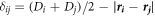 , while the unit vector joining the centers of two particles
  . The terms
  and
and  represent the normal and tangential relative velocities, respectively.
  is the effective mass and
  is the tangential displacement vector between the two particles. Here Kn and Kt represent the normal and tangential nonlinear spring constants, respectively, and γn and γt are the normal and tangential dissipation coefficients. The magnitude of
  is limited to the maximum of
  to satisfy the slipping criteria where μc is the frictional coefficient among particles. Table 1 describes the values of these simulation parameters.
Table 1. The values of parameters used in the simulations.
| Parameters | Value |
|---|---|
| Kn |

|
| Kt |

|

|

|

|

|

|
0.2 |
| dt |

|
In the simulations, we use a similar system to the one used in the experiments. We consider a cylindrical container with a rod of diameter D buried down to a certain depth. The diameter of cylindrical granular layer is fixed as  where d = 10−3 m is the unit of length scale in the simulations. The cylinder is filled with particles of diameter Dg with a polydispersity of 10% by randomly pouring them from the top. The packing fraction ϕ in the simulations is varied roughly from 0.6 to 0.637. The number of particles poured in the vessel ranges from 15 850 to 53 500 depending on Dg. The height of the granular particles inside the cylinder is approximately
  with the rod being inserted till a depth of 35d from the free surface as shown in figure 2. The density of the granular particles and the rod is set as ρ = 2500 kg m−3. The magnitude of gravitational acceleration is g = 9.8 m s−2 in the negative z direction and the effective diameter of the rod is
  . The rod is constructed by using smaller particles of diameter
  along the circumference of a cylinder of diameter 0.875d and thus,
  .
.

Figure 2. Initial configuration example of the numerical simulation with Dg/D = 1.422. The black rod is at the center of the cylinder and the blue particles are the granular particles. The depth of the insertion of the rod inside the cylinder is roughly 35d. Here the length scale unit is  .
.
Download figure:
Standard image High-resolution imageIn the simulations, we pull the rod at a constant velocity of  in the positive z direction which is 5–10 times higher than the velocities in the experiments. We use this velocity because the computational time for such low velocity becomes extremely long. Decreasing the pulling velocity even further is infeasible. We believe that the simulations are still in the same regime as in experiments because we observe the sliding behaviors that are similar to the experiments. The total number of timesteps is 50 million which may take about few days of computational time for larger Dg while several weeks for smaller Dg on 42 CPU. Additionally, the range of
  in the simulation study is limited in Dg/D ≥ 1.4.
We use Large-scale Atomic/Molecular Massively Parallel Simulator [26, 27] for the simulations. Ovito [28] and VMD [29] are used for the post-simulation visualization.
3. Results and analyses
3.1. Experimental results
Typical examples of the experimentally acquired raw data of δz(t) and F(t) are shown in figure 3 (Dg/D = 1.45). In the early stage of withdrawing, static granular friction sufficiently resists the pulling force. In this regime, F increases roughly by R = 1 mN s−1 and the displacement δz is almost constant (δz ≃ 0). When the pulling force exceeds a certain limit (at t ≃ 73 s; shown by vertical dotted line in figure 3), yielding (sliding) at the frictional interface among the rod and particles occurs. In the late stage, the steady sliding with a constant speed vmax can be observed. In this regime, the granular dynamic friction balances with the pulling force. However, immediately after t = 73 s, pulling force is not steady and it gradually approaches to the steady state. While the fluctuation of F in this transient state could be interesting, here we focus only on the steady state as a first-step approach.

Figure 3. Typical example of experimental raw data with Dg/D = 1.45: (a) δz(t) and (b) F(t). In panel (b), the pulling force F increase linearly with time t in the early stage of pulling, obeying a control signal: F = Rt, where R = 1 mN s−1 is a fixed parameter. In this regime, displacement z is negligibly small. After the yielding at t = 73 s, almost the steady slip with vmax = 8 μm s−1 can be observed and F(t) approaches the steady force value  . The horizontal solid and dashed lines indicate Fend and Fend ± 3σend, respectively.
Download figure:
Standard image High-resolution imageTo characterize the steady granular friction force  , we identify the steady state of F as follows. The force at the final stage, which is restricted by the limit of displacement of PCM-nano (≃4 mm), is defined as Fend. Then, the standard deviation in the last 5 s is measured and quantified as σend. The average value of resistance force
  are computed by the average in the range satisfying the condition
  from the final measurement point.
The relation between steady resistance force  and initial packing fraction ϕ is shown in figure 4(a). For all
  cases, one can confirm that
  is an increasing function of ϕ. This positive correlation between
  and ϕ is natural and has been observed in the similar previous experiments [8, 9]. The measured
  can be transformed into the frictional coefficient by the relation
  . The simplest assumption for the normal force N is hydrostatic pressure times surface area of the rod. Then, the normal force acting on the rod surface is written as
 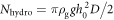 , where ρg = ρϕ. Using these quantities,
  can easily be computed as shown in figure 4(b). One peculiar feature observed in figure 4(b) is the extremely large μ value in the large ϕ regime. The value of μ exceeds unity and reaches even around 6. Such a large μ value is unexpected because we use cohesionless particles (macroscopic glass beads). For cohesionless particle system, μ should be less than unity.

Figure 4. Experimentally obtained  and μ versus ϕ. (a) Measured steady force
  versus ϕ. Colors and symbols indicate the value of
  . Although the positive correlation between
  and ϕ can be confirmed in all data, the increasing behavior depends on geometry,
  . Dotted curves represent
  computed with equations (7) and (8) for Dg/D = 0.13, 0.33, and 2.66. (b) Frictional coefficient
  versus ϕ computed by assuming hydrostatic pressure. The extremely large μ value in large ϕ regime suggests that the hydrostatic pressure is not a good approximation in this experimental setup.
Download figure:
Standard image High-resolution imageOne might imagine the complex particle motions during the withdrawing for the origin of this peculiar behavior. However, it is difficult to detect the clear particle motions and/or variation of ϕ before and after the withdrawing. This implies that any significant macroscopic deformation of the granular layer (rearrangements of particles) is not induced by the withdrawing. Therefore, the resistance force must originate from the frictional slipping at the interface among particles and rod. However, the estimated value of frictional coefficient μ is much greater than the expected value.
3.2. Jammed cylinder
From the above observations, we consider that the simple hydrostatic-pressure approximation does not work well in this experimental setup. Instead, here we consider that the force chain structures developed by the shearing [30] could form the solidified zone with radius nDg (figure 5). Here, n indicates the normalized radius of solidified cylindrical zone. Then, this solidified region could cause the extremely large normal force on the surface of the rod because the shear-induced force chains are not parallel to the gravitational direction as schematically shown in figure 5. This oblique force-chain structures result in the increase of normal force acting on the rod. However, it is difficult to provide a direct evidence of the solidification based only on the experimental data. Thus, we use numerical simulations to access the internal force structures within the sheared granular layer.

Figure 5. Schematic illustration of the jammed cylinder which corresponds to the effectively solidified cylindrical region. The solidification is caused by the shearing due to the rod withdrawing. The developed force chains within the solidified zone redirect the gravitational loading to the normal force acting on the surface of the rod  . As a result,
  can become large mainly by the increase of Njam.
Download figure:
Standard image High-resolution image3.3. Numerical results
In this subsection, we present the results obtained by the numerical simulations. We report the average withdrawal force  as the average of the instantaneous withdrawal force once the steady state is achieved just like experiments. The average withdrawal force
  is shown in figure 6(a) in which the data trend is qualitatively similar to that observed in the experiments. The force exerting on the rod can be computed by using shear stress S and pressure
  where
where  is the depth of the rod: the withdrawal force
  and the normal force
 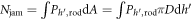 where dA is a small area on the surface of the rod and
  is a small length of the rod along z direction. Although we calculate
  by averaging the instantaneous force acting on the rod in the steady state regime,
  should be measured using this scheme instead of simple hydrostatic form. In addition, we compute the stress tensor for each particle including the ones conforming rod as follows (by assuming ith particle has a diameter Di and is in contact with jth particle) [31],

Here,  is the contact force and
  is the position vector from the center of ith particle to the point of contact. We calculate the pressure Pi on each particle as
  . Based on this pressure, we calculate the
  on the rod as shown in figure 6(b). The increase of Njam associated with ϕ can be observed. Then we show
  in figure 6(c). In figure 6(c), μjam remains almost constant with respect to the packing fraction for a given
  . Although it could slightly depend on
  , the obtained values of μjam are close to μc = 0.2.

Figure 6. Numerically obtained  , and μjam. (a) The variation of normalized average withdrawal force
  with respect to ϕ for various
  is presented. (b) The variation of normal force Njam on the rod versus ϕ is plotted. Red dotted line indicates the Nhydro. (c) The variation of
  with ϕ is shown.
Download figure:
Standard image High-resolution imageThus, the ϕ-dependent increase of Njam is a plausible reason for the pseudo large friction found in the experiments. Note that any macroscopic compaction of the granular layer cannot be observed in the numerical simulations as well. Namely, tiny rearrangement of the packing structures induced by the rod pulling must develop the effective solidification. Furthermore, as mentioned in section 3.1, hydrostatic pressure cannot explain the physical reason for large  value. Therefore, we will analyze the details of the difference between Nhydro and Njam and the geometry of shear-jammed region, in the next subsection.
3.4. Evidence for solidification by shear-jamming
In order to understand the physical mechanism governing the growth of Njam, we firstly compute, the average pressure acting on particles as a function of depth from the surface z when the rod is not being pulled, i.e. in an initial static state. The static pressure  is calculated by the average of pressure on particles that are located at a depth of
  . Measured
  with Dg/D = 1.422 and ϕ = 0.621 is plotted in figure 7(a). The pressure seems to saturate after a certain depth due to Janssen effect (see e.g. [1]). However, the rod is inserted down to the depth 35d where the pressure linearly increases as a function of depth (vertical line in figure 7(a)); hydrostatic regime in a static state. Except the region close to the wall, P(z) is constant and independent of radial distance from the rod when the rod is not being pulled out.
  denotes the average at the fixed depth z. This result insists that the hydrostatic pressure is indeed the most crucial factor determining the pressure in the static (not sheared) granular layer.
Figure 7. Numerical data for shear-jammed solidification. (a) The variation of average pressure on a particle located at a depth of  with respect to the depth when the rod is not being pulled out. (b) The variation of
  with respect to the radial distance
  from the rod. Rjam becomes zero around
  independent of the depth z. This suggests a cylindrical shear zone. For the data in (a) and (b), Dg/D = 1.422 and ϕ0 = 0.621. (c) Radius of the shear-jammed cylinder nDg versus ϕ is shown. One can confirm the clear positive correlation.
Download figure:
Standard image High-resolution imageHowever, when the rod is being pulled out, this is not the case. Pressure on a particle becomes a function of the radial distance from the rod  due to the shearing induced by the withdrawn rod. Here, we measure the average pressure on a particle in the range of a radial distance
  and a depth
 . We observe that once the steady state is achieved, the particles near the rod experience relatively higher pressure which also increases with depth. To characterize the degree of pressure increase, we compare
  with a hydrostatic pressure
  by using a form,

which becomes zero when the depth-dependent pressure is simply identical to the hydrostatic one. In figure 7(b), we plot  with Dg/D = 1.422 and ϕ = 0.621. It can be seen that a high pressure region is formed near the rod. This is a clear evidence of shear-induced pressure increase. We consider this pressure increase causes the effective solidification (shear jamming). In the large
  regime,
  approaches to
  . This implies that the region of shear jamming is limited in the vicinity of the rod, as schematically illustrated in figure 5. One can observe that there exists a unique distance from the rod where
  is fulfilled. This proves that the shape of the shear zone is cylindrical. Through the simulations, it is difficult to verify the details of Dg dependence of this crossover (
 ) point, due to the limitation of computational time for small
  cases or the limited quality of statistics for large
  case. In figure 7(c), the variation of the radius of shear cylinder nDg against ϕ with Dg/D = 1.422 is displayed. It can be clearly seen that n increases with ϕ.
Now, we are sure about the physical reason for the large  in the large ϕ regime. The effective solidification due to the shear jamming is caused in the vicinity of the withdrawn rod. Then, the next problem to be studied is
  and ϕ dependence of the shear-jammed region. To this end, the systematic analysis of the experimental data is much more feasible than performing the complete set of numerical simulations. Therefore, we will go back to the analysis of the experimental data in the next section.
4. Discussion
4.1. Size of shear-jammed (solidified) cylinder
As mentioned so far, the origin of large  is the growth of shear-jammed (solidified) zone. Thus, we discuss the relation between shear jamming by the rod withdrawing and initial packing fraction. When the rod is withdrawn, particles around the rod are sheared. As a consequence, if the initial packing fraction is large enough, the shear-induced jamming could be developed in the granular layer. By this shear-jam effect, a certain amount of particles close to the rod would be effectively solidified.
To understand ϕ- and  -dependent behaviors of
  , we revisit the solidified cylinder model introduced in [7]. In the model, we assume that the frictional slipping occurs at the interface between the rod and particles. We also assume that the frictional coefficient of the slip can be regarded as a constant. We additionally assume that the normal force acting on the interface among the rod and particles is proportional to the mass of the solidified cylindrical region since a part of gravitational loading is redirected to the surface of the rod due to the inclined force chain structures. To specifically estimate the normal force acting on the rod surface Njam, the redirection ratio of the vertical force to the horizontal normal force, κ (Janssen parameter [1]), should be introduced. However, the precise determination of κ value is not very easy in general (see e.g. section 3.7 in [32]). Actually, the specific value of κ is not very important because we later discuss the critical divergence of the characteristic length scale (solidified cylinder radius) which is independent of the value of κ. Thus, in this study, the effective frictional coefficient
  is used in the following calculation. Then, similarly to Coulomb–Amonton's frictional constitutive law, the force is expressed as
  , where Mjam is the mass of solidified region and
  can be regarded as a constant. Using this solidified cylinder model, the increase of
  in large ϕ regime can be transformed into the expansion of the effective radius of solidified (jammed) region, n, in units of particle diameter, i.e. the actual radius of the solidified zone is nDg. By considering the cylindrical geometry,
  is written as [7],

By solving this equation, n is written as

where,  . The computed n values for all the experimental runs are shown in figure 8(a). To obtain the specific values of
  is employed. This value is reasonable by considering the typical frictional coefficient between glass and steel (μ = 0.18 [33]) and the practical Janssen parameter value (κ ≃ 0.5). As can be seen in figure 8(a), n has a divergent tendency against ϕ. However, the data show systematic variation depending on the size ratio
  .
.

Figure 8. Experimental data for the critical divergence of the radius of shear-jammed region. (a) The estimated normalized radius n of solidified (shear-jammed) cylindrical region (figure 5) in units of particle diameter Dg. (b) The scaled radius of solidified cylinder n(Dg/D)α is shown as a function initial packing fraction ϕ. The solid gray curve represents the fitting by equation (7). The inset displays n(Dg/D)α versus ϕc − ϕ in log–log plot.
Download figure:
Standard image High-resolution image
4.2. Divergence of the size of shear-jammed cylinder
To understand the underlying physics governing the behavior of n shown in figure 8(a), we analyze the  dependence of n. As a result, we find that the relation between n and
  for various ϕ is scaled by the power-law relation
  with a characteristic exponent α = 0.56. We have confirmed that this relation is actually consistent with the previous study [7], in which the steady resistance force is a decreasing function of
  . Using the relation, the scaled size of shear-jammed cylinder, n(Dg/D)α, is plotted as a function of ϕ in figure 8(b).
From the data trend observed in figure 8(b), we consider that n shows a critical divergence as ϕ approaches the critical (jamming) point ϕc. To characterize the critical divergence of the length scale n, the data are fitted to the form,

where β is a critical exponent characterizing the divergence and n0 is a fitting parameter. The solid gray curve shown in figure 8(b) shows the least square fitting by equation (7). The already estimated value α = 0.56 is used as a fixed parameter. Then, the fitting-parameter values are obtained as n0 = 0.35, ϕc = 0.62, and β = 1.3. In the inset of figure 8(b), the relation between  and ϕc–ϕ is displayed in the log–log style. The data behavior is consistent with the critical divergence modeling.
4.3. Constitutive law for withdrawing granular friction
Altogether, now we can conclude the effective constitutive law for the granular withdrawal frictional force as follows,

where n obeys the critical divergence form (equation (7)). This form is equivalent to equation (5). The parameter values for the glass beads and cylindrical stainless-steel rod case are  , and β = 1.3. This constitutive law includes the effective frictional resistance force governed by the shear-induced jamming and geometrical conditions (size ratio and cylindrical shear-jammed zone). Although this form is quite different from the conventional granular frictional constitutive law using the inertial number (e.g. [3–6]), the current experiment actually focuses only on the very small inertial number regime to reveal the effects of
  and ϕ. As discussed in [7], the rough estimate of I can be
  . By substituting characteristic values (vmax ≃ 10−5 m s−1 and h ≃ 5 mm), we can estimate I is less than 10−4. In addition, we assume that the interfacial friction between the rod and particles is almost constant. While the current analysis relies on these assumptions, we find that the idea of critical divergence of the characteristic length scale by the jamming can be applied also to the vertical withdrawing system, just like other granular systems (e.g. [15, 34, 35]). Moreover, the form of critical divergence of the characteristic length scale written in equation (7) might be universal and independent of the details of experimental setup. However, the physical origin of the scaling exponents (α = 0.56 and β = 1.3) has not been revealed in this study. This is still an open problem. The computed
  values for Dg/D = 0.13, 0.33, and 2.66 are shown as dotted curves in figure 4(a) by each corresponding color. Although these curves basically reproduce the experimental data, the quality of agreement is slightly limited. For instance, the constitutive law underestimates
  in large Dg/D(= 2.66). Since the constitutive law is derived on the basis of simple scaling analysis, the law can be used to roughly estimate the value of
  . In this study, the static granular friction without any perturbation has been investigated. As a next step, the effect of perturbations (air flow and/or vibration) applied during the withdrawing is also an interesting topic for future study to elucidate the physical mechanism of frictional constitutive law for granular matter.
5. Conclusion
In this study, granular frictional constitutive law was experimentally obtained from the relation among the steady resistance force, packing fraction, and size ratio between particles and withdrawn object. The increase of steady frictional resistance  by increasing ϕ can be understood by the shear-induced solidification of the granular layer. The evidence of this shear-jammed (solidified) zone was obtained by numerical simulation. According to the numerical results, the cylindrical region around the withdrawn rod is effectively solidified by strong contact forces. The size of solidified region has a positive correlation to the initial packing fraction. From these numerical evidences, we conclude that the simple model of a cylindrical solidified zone can explain the pseudo increase of granular friction. Then, the size of cylindrical solidified zone was systematically estimated using the experimental data. Using these data, we built an empirical granular frictional constitutive law. In the modeling, we considered the elongation of the force chains developed by shearing. Due to this force chain developments, the cylindrical unit around the rod seems to be solidified by shear jamming. The normalized radius of this solidified cylindrical region n is estimated by the experimental result. The relation among n, Dg/D, and ϕ was analyzed and the empirical form for estimating n was obtained as equation (7). Although the obtained empirical form is consistent with previous studies, the physical meaning of the estimated critical exponents α and β in equation (7) has not yet been understood well. To establish a more comprehensive and universal granular frictional constitutive law, we have to pay attention also to other parameter dependencies as well (e.g. sliding velocity, particle shape etc).
Acknowledgments
HK thanks JSPS KAKENHI Grants No. 15H03707 and 18H03679 for financial support. KAR and SK would like to thank Param-Ishan, high performance computing facility of IITG.