


Abstract
A conventional electrospinning setup was upgraded by two turnable plate-like auxiliary high-voltage electrodes that allowed aligned fiber deposition in adjustable directions. Fiber morphology was analyzed by scanning electron microscopy and attenuated total reflection Fourier transform infrared spectroscopy (FTIR-ATR). The auxiliary electric field constrained the jet bending instability and the fiber deposition became controllable. At target speeds of 0.9 m s−1 90% of the fibers had aligned within 2°, whereas the angular spread was 70° without the use of auxiliary electrodes. It was even possible to orient fibers perpendicular to the rotational direction of the target. The fiber diameter became smaller and its distribution narrower, while according to the FTIR-ATR measurement the molecular orientation of the polymer was unaltered. This study comprehensively documents the feasibility of directed fiber deposition and offers an easy upgrade to existing electrospinning setups.
Export citation and abstract BibTeX RIS
1. Introduction
Electrospinning is a versatile method for the production of nonwoven fibers ranging in size from nano- to microscale. Therefore, it is adopted in various fields of science, e.g. tissue engineering, energy storage, sensors and environmental engineering [1]. The process was developed by Formhals and has been studied thoroughly in the last decades [2–4]. Although the method is simple, formation of the fibers and their deposition on a target are influenced by many parameters. While elementary parameters affecting the polymer fiber properties like the polymer solution, distance between the electrodes and the applied voltage are increasingly understood, it is still not possible to fully control the fiber path from the jet onset to deposition [5, 6]. Various instabilities, such as the electrospinning jet bending and the buckling instabilities, lead to unpredictable deposition, which is the limiting factor in producing straight and aligned fibers [7–9].
However, continuous straight and aligned electrospun fibers are desirable for products with anisotropic properties such as cell scaffolds. Although in tissue engineering the random fiber deposition is generally appropriate, as it mimics the structure of the extracellular matrix well, increasing control over the fiber deposition offers several advantages: contact guidance, i.e. cells on the scaffold are promoted to collectively align in a desired direction, is triggered by aligned surface layers. For example, in natural vessels, smooth muscle cells align helically on the lumen [10]. Furthermore, mechanical properties can be engineered by aligning anisotropic fibers within the fabric, as is the case with collagen fibers in the outer layers of the natural vessel [10]. Thus a prospective method of alignment is most versatile if it allows an easy transition between oriented and non-oriented layers. Many techniques have been developed to control fiber orientation and obtain aligned fibers [11, 12]. Some methods involve the modification of the target to yield aligned fibers, for example, by use of a rotating mandrel [13–15]. By varying the surface speed of the collector the degree of alignment can be somewhat adjusted. Wu et al introduced parallel auxiliary electrodes behind the target to control the width of the deposited, aligned fibers [16]. Li et al showed that fibers can be aligned in the gap between two collecting electrodes [17]. In a later work they investigated the effect of the area and geometric shape of the insulating gap on fiber deposition [18]. The alignment effect of such gaps is limited by the thickness of the deposited layer because orientation becomes more random as more fibers are deposited [19]. A modification uses two collecting rings to achieve fiber alignment across the gap between them [20]. However, this method remains similar to the 'gap method' and yields fibers of a limited length.
Methods that diminish jet instabilities by introducing auxiliary electrodes with various shapes achieve that by manipulating the external electric field to control the fiber path and the deposition area of the electrospun fibers [21–26]. Another effective method to facilitate fiber alignment uses counter electrodes [27–29].
The reviewed methods to align fibers have different drawbacks, e.g. the design of special targets is possible but can neither be universally applied nor can the degree of alignment be switched instantaneously. Whereas the method of aligning fibers by a rotating target is more general, the degree of fiber alignment is limited even at very high rotational speeds. Furthermore, with the reviewed methods it is not possible to deposit fibers inclined to the rotational direction of a mandrel, which is useful, for example, for the fabrication of compliance-matched vascular prostheses. As the bending instability is the main origin of misorientation, we hypothesize that the fiber alignment can be improved by constraining the bending instability within a plane perpendicular to the target rotation. Furthermore, this constrain will allow patterned deposition, irrespective of the target motion.
In this study, turnable auxiliary electrodes were used for the generation of a symmetrical auxiliary electric field that narrowed the electrospinning jet bending instability. This simple and versatile approach yields aligned polymer fibers with a focusable deposition area. In addition, the turnable auxiliary electric field allows to freely adjust the deposition orientation, regardless of the used target electrode.
2. Materials and methods
2.1. Materials
A polymer solution of 5% (w/w) polyurethane (Pellethane® 2363-80A; Lubrizol, Cleveland, USA) in 1,1,1,3,3,3-hexafluoro-2-propanol (Sigma-Aldrich, Vienna, Austria) was used for the examinations. Pellethane® 2363 80-A polyurethane is a thermoplastic copolymeric elastomer that is commonly used for medical devices and electrospinning experiments [30, 31]. It is physically crosslinked by extensive hydrogen bonding involving a soft block and hard block, where the former is poly(tetramethylene ether)glycol while the latter is an urethane comprised of tetramethylene ether glycol and diphenylmethan-4,4'-diisocyanat [30, 32].
2.2. Electrospinning
The electrospinning setup is depicted in figure 1. It comprises a syringe holding the polymer solution. The syringe is fitted with a blunt-ended 21 gauge needle, connected via an alligator clip to a high-voltage power supply (CPP 300-304-24-5, ET System electronic GmbH, Altlussheim, Germany). A custom-made infusion pump delivered the polymer solution at a constant flow rate of 0.01 ml min−1 in all experiments. The target was mounted on a rotatable drill chuck that could also be moved in the horizontal x direction. The standard y distance between the needle and the drill chuck was 12 cm, and the potential of the needle, U0, was kept at −15 kV. To narrow the jet bending instability, two symmetric, entirely turnable, rectangular auxiliary aluminum electrodes (12 × 12 cm2 area, 2 mm thickness) were positioned around the needle and operated at a high voltage of the same polarity as the needle but with an adjustable amplitude Uaux. The standard distance d was 12 cm, the clearance between the target and the auxiliary electrodes yte was 2 cm, and the standard voltage Uaux was −14 kV unless noted otherwise. Three settings were used to evaluate the effect of the auxiliary electrodes on the fiber deposition (figures 2(a)–(c)).

Figure 1. Top view of the electrospinning layout. It contains a rotating target that could also be stationary and flat. The auxiliary electrodes generate a strong focusing force in the symmetry plane (y–z). The voltage Uaux applied to the auxiliary electrodes can be varied independently from that on the needle U0, but it has the same polarity.
Download figure:
Standard image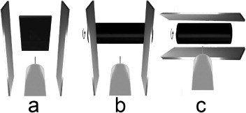
Figure 2. View from behind the jet source (in the positive y direction): three electrospinning configurations and the arrangement of the auxiliary electrodes are depicted. (a) Setting 1: stationary, flat target with auxiliary electrodes positioned at 0°; (b) setting 2: rotating target with auxiliary electrodes held at 0°; (c) setting 3: rotating target with auxiliary electrodes positioned at 90°.
Download figure:
Standard image2.2.1. Setting 1 (stationary target).
A flat, stationary, grounded target made of a carbon fiber plate (10 × 10 cm2) was used to demonstrate the focusing effect of the deposited fibers. The effect of the auxiliary electrodes on focusing was investigated by varying the applied voltage Uaux and the distance d between the electrodes. The test spinning was carried out for 100 s, with the results photographed from a fixed position. The area of fiber deposition on the photograph was then fitted with an ellipse using the image analyzing software ImageJ [33]. The total area of the ellipse and the length of its minor semiaxis were used to quantify the focusing effect. The experiment was repeated five times for each parameter set.
2.2.2. Setting 2 (rotating target).
A cylindrical rotatable aluminum target with a diameter of 4 cm was wrapped with aluminum foil. To obtain the orientation of the very first layer, the spinning time was set to 5 s. The cylinder was horizontally translated to further decrease the fiber density. The spun area was photographed with a stereo microscope (SM8, Zeiss, Jena, Germany, 64 × magnification) and observed in a scanning electron microscope (SEM, JEOL JSM 5400, Japan) to analyze individual fibers. The fiber alignment for various circumferential speeds was compared using settings with and without auxiliary electrodes. The diameters and angles of all fibers were measured using the ImageJ software. Ten measurements over at least two images were used to calculate the diameter distribution. Further, we characterized the resulting buckling instability, which originates from the jet impingement on the target and produces patterns of meandered fibers [9]. The relationship between this buckling instability and the collection speed was quantified by an image analysis of the buckling wavelength.
2.2.3. Setting 3 (rotating target with turned auxiliary electrodes).
Using this setting, fiber orientation was studied on the rotating target with auxiliary electrodes positioned at 90°. This configuration exerts a strong focusing force in the (x–y) plane. The circumferential speed of the target was set to 1 mm s−1.
2.3. FTIR-ATR spectroscopy
Attenuated total reflection Fourier transform infrared (FTIR-ATR) spectroscopy (Bruker Alpha equipped with the platinum ATR module A220/D-01; Bruker, Ettlingen, Germany) measurements were performed with a resolution of 2 cm−1 in the range of 1600–1800 cm−1. We used samples electrospun via setting 2, with and without electrodes, and a cast polyurethane spinning solution as a reference. The samples were inserted into the spectrometer so that the side of the first electrospun deposition layer faced the ATR crystal. The spectra were averaged over 1000 measurements. Peak deconvolution was conducted with a data processing software (Origin 8.5; OriginLab Corp, Northampton, USA) assuming a Voigtian peak shape.
3. Results
Development of a strong focusing force between two electrodes was clearly demonstrated by comparison of electrospinning with and without electrodes. Figures 3(a) and (b) demonstrate the effect of different voltages applied to the auxiliary electrodes in setting 1. The focused deposition plane followed the turning of the auxiliary electrodes (figure 3(c)). By increasing the voltage on the auxiliary electrodes the polymer jet was essentially constrained to a focus plane midway between them. When the auxiliary electrodes were not used the jet was free to move and deposition took place over the whole target (not shown here).

Figure 3. Influence of the auxiliary electrostatic gradient field on the fiber deposition area (setting 1) for a spinning time of 100 s: (a) Uaux = −5 kV, (b) Uaux = −10 kV. (c) Superposition of spinning on the target from experiment (b) with auxiliary electrodes turned at 30° and 60°, at Uaux = − 10 kV. The scale bar is 1 cm for all images.
Download figure:
Standard imageThe effect of the auxiliary electrostatic gradient field was confirmed by visual observations of the jet. The shape of the fiber deposition with setting 1 corresponds to the motion of the electrospinning jet that is schematically depicted in figure 4.
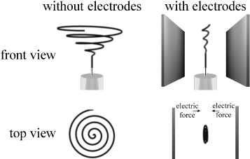
Figure 4. Simplified depiction of the bending instability with and without auxiliary electrodes. In both cases there is a straight jet region until the onset of the bending instability. Note that the electrical forces imposed on the jet lead to a strong narrowing of the bending instability in the horizontal direction, but also diminish its extent in the vertical direction. The spiraling trajectory is idealized and does not necessarily resemble those occurring during electrospinning.
Download figure:
Standard imageThe impact of the chosen values of Uaux and the distance d between the auxiliary electrodes on the area and shape of the fiber deposition is shown for three different electrode voltages in figure 5. The spun area is reduced with the reduction of the distance between the auxiliary electrodes. A minimal deposition area of 0.61 ± 0.15 cm2 exists for d = 7.0 ± 0.3 cm and Uaux = −10 kV. A further decrease in d generates a repulsive field that prevents fiber deposition. Higher electrode voltages require larger values of d because of the higher repulsive field strength near the needle. Consequently, the effect of electrode distance can be compensated by choosing an appropriate electrode voltage Uaux.

Figure 5. Spun area (a) and the length of minor semiaxis of the ellipsoid-shaped fiber deposition area (b) as a function of the auxiliary electrode potential Uaux and spacing d. The error bars display the standard deviation of five measurements.
Download figure:
Standard imageFiber alignment on a rotating target was achieved in and perpendicular to the direction of rotation. In the former case (setting 2) fiber alignment at the nanoscale could be achieved at a surface speed of 4.5 m s−1 (figure 6(a)). In the latter case macroscopically aligned fibers were deposited perpendicular to the rotation direction using setting 3 (figure 6(b)). A comparison of settings 2 and 3 clearly shows the difference of alignment at the nano- and microscale (figure 6(c)). At the macroscale, aligned fibers consist of many adjacent fibers but with a considerably narrowed deposition width. The ability to change the fiber orientation by turning the auxiliary electrodes without interruption of the spinning process should allow connecting fibers as in non-oriented electrospinning.
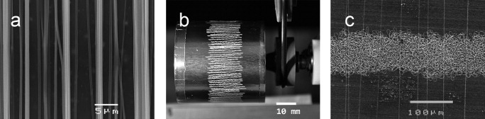
Figure 6. Degrees of fiber alignment: (a) on a rotating target with a surface speed of 4.5 m s−1 (setting 2), (b) with orientation perpendicular to the direction of rotation, using auxiliary electrodes turned at 90° (setting 3), (c) magnified comparison of the macroscopic fiber orientation from experiment (b) with straight and aligned electrospun fibers as described for (a).
Download figure:
Standard imageFiber orientations obtained with setting 2 at various surface speeds on the cylindrical target, with and without the use of the auxiliary electrodes, are shown in figure 7. The fiber alignment was poor without the use of auxiliary electrodes, even at high circumferential velocities (figures 7(a)–(c)), whereas straight and aligned fibers were deposited with the auxiliary electrodes (figures 7(d)–(f)). The insets in figures 7(a)–(f) are SEM images of the observed buckling instabilities. Figure 8 shows a comparison of the deviation of the fiber angle from the mean, with and without the use of auxiliary electrodes at different surface speeds. The introduction of the auxiliary electrodes improves the fiber alignment by more than an order of magnitude. At a speed of v = 0.9 m s−1, 90% of the fibers had an angular deviation of less than 2°, whereas the deviation was 70° at the same speed without the use of auxiliary electrodes.

Figure 7. Optical micrographs showing fiber deposition onto a moving target without (a)–(c) and with (d)–(f) auxiliary electrodes at various surface speeds: (a), (d) 0.9 m s−1; (b), (e) 2.7 m s−1; (c), (f) 4.5 m s−1. The bending instability diminishes when the auxiliary electric gradient field (d)–(f) is applied. The insets in (a)–(e) are scanning electron micrographs showing a magnification of the particular buckling of the deposited fibers. Buckling instabilities are not present when using auxiliary electrodes at a surface velocity of 4.5 m s−1 (f). The scale bar corresponds to 200 μm (a)–(f).
Download figure:
Standard image
Figure 8. Fiber angle deviation at various collecting speeds, (a) without and (b) with auxiliary electrodes.
Download figure:
Standard imageWe attribute a large fiber curvature to bending, and a small fiber curvature to buckling instabilities. Both are observed during electrospinning without auxiliary electrodes (figures 7(a)–(c)). By applying the auxiliary electric field the bending instability can be considerably narrowed (figures 7(d)–(f)). The buckling instability that occurs as the jet impinges on the target results in a meandered, i.e. often sinusoidally or at least periodically shaped, fiber deposition (figures 7(a)–(e)). At high surface velocities (∼4.5 m s−1) buckling irregularities disappear (figure 7(f)). The buckling wavelength can be analyzed to characterize the relationship between the buckling instability and the surface speed. At increasing circumferential speeds the wavelength, which represents the length of the instability repeating unit, became larger. This is especially true for the setup with auxiliary electrodes, where the buckling wavelength increased exponentially with the circumferential speed as shown in figure 9. Without the auxiliary electrodes the curved fiber deposition due to the overlying bending instability hampered the measurement of the buckling wavelength, even at high surface speeds.
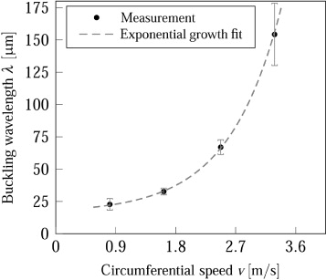
Figure 9. Buckling wavelength as a function of the circumferential speed.
Download figure:
Standard imageThe effect of the auxiliary electric field and target speed on fiber diameter is shown in figure 10. As the target speed was increased from 0.9 to 4.5 m s−1, the diameter of the deposited fibers decreased from 1.19 ± 0.41 to 0.70 ± 0.23 μm, without the use of auxiliary electrodes. In contrast, fibers electrospun with the auxiliary electrodes had a diameter of 0.60 ± 0.15 μm at 0.9 m s−1 and 0.51 ± 0.20 μm at 4.5 m s−1.

Figure 10. Effect of the target speed and the use of auxiliary electrodes on the fiber diameter.
Download figure:
Standard imageThe FTIR-ATR spectra of the samples electrospun with and without electrodes and for the cast sample are plotted in figures 11(a)–(c), respectively. The 1702 cm−1 peak can be assigned to the hydrogen-bonded carbonyl ( ) stretching vibration whereas the non-bonded
  mode is located at 1730 cm−1 [34, 35]. Since this hydrogen bonding is mainly of intra-urethane origin, [34] hard blocks possessing free hydrogen bonds are thought to reside mixed in the soft phase or at the interface between soft and hard blocks.
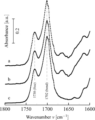
Figure 11. Pellethane FTIR-ATR absorbance spectra in the carbonyl stretching region for scaffolds (a) electrospun with electrodes, (b) electrospun without electrodes and (c) cast from spinning solution. The peak at 1730 cm−1 is assigned to the carbonyl vibration without hydrogen bond association (free), while the one at 1702 cm−1 corresponds to hydrogen bonding. Peak height and area analysis is presented in table 1.
Download figure:
Standard imageThus the degree of phase separation between the two blocks can be determined via IR measurements. According to Seymour et al [35] this segregation can be quantified by the 'hydrogen-bonding index' R:
where B is the absorbance at the corresponding peak. The index R directly translates into the concentration c ratio of bonded to free carbonyl groups, because B = c·l·ε (the Beer–Lambert law) and both fractions of l and ε are equal to unity as the path length l and the extinction coefficient ε are the same in the bonded and non-bonded cases [36]. The derived values of R are presented in table 1. Nevertheless, Srichatrapimuk and Cooper [37] argued that R underestimates the hydrogen-bonded peak and proposed to calculate the fraction X of hard segments encircled by hard segments as:
Here A is the area under the peak with the corresponding wavenumber. The deconvoluted peak values for A and the calculated values of X are presented in table 1.
Table 1. FTIR analysis of three different samples showing the values of absorbance B, spectrally deconvoluted peak area A for the corresponding wavenumber, fraction of hard segment segregation X and 'hydrogen-bonding index' R.
| Sample | B1702 (au) | B1730 (au) | A1702 (au) | A1730 (au) | X | R |
|---|---|---|---|---|---|---|
| a | 0.291±0.005 | 0.546±0.005 | 18±1 | 7.3±0.4 | 0.71±0.02 | 1.87±0.02 |
| b | 0.288±0.005 | 0.534±0.005 | 18.6±0.5 | 7.1±0.4 | 0.72±0.02 | 1.85±0.02 |
| c | 0.290±0.005 | 0.556±0.005 | 17.5±0.6 | 4.7±0.3 | 0.79±0.02 | 1.92±0.02 |
a, electrospun with electrodes; b, electrospun without electrodes; c, cast spinning solution.
4. Discussion
Although the morphology of electrospun scaffolds can be controlled to some degree, basic electrospinning yields random fiber fabrics that result from uncontrolled fiber deposition. The technique described here can substantially overcome these limitations, offering a simple focusing method within an adjustable deposition plane.
The width of the deposition area can be easily adjusted by changing either the distance between the auxiliary electrodes or by varying the applied voltage, which increases the process performance and avoids material loss. The narrowing of the fiber deposition surface in an ellipse-shaped area (figures 3(a)–(b)) with an adjustable minor semiaxis is due to the auxiliary electrodes. We want to emphasize that the focusing effect, as determined by the ellipse minor axis (figure 5(b)), is even stronger in the initial phase of the spinning process, but as the deposited polymer fibers cover the conductive plate it increasingly becomes an insulator and the jet deviates to the adjacent, non-coated regions. This is associated with the 'jet stepwise jumping' to a nearby area, rather than a widened bending instability. Therefore, as figure 3 is a superposition of many jumps and does not reveal the process dynamics, the ellipse minor axis (e.g. in figure 3(b)) is not one-to-one related to the degree of the bending instability containment and must be considered as a conservative upper boundary. The deposition narrowing is strong perpendicular to the plates (x direction, based on figure 1) but is much weaker parallel to them (z direction). The remaining degree of freedom parallel to the electrodes in the deposition plane enables macroscopic orientation of the fibers in this direction, even for slowly moving or stationary targets (figures 3(c) and 6(b)). There is a maximum of focusing ability (figure 5), as a too strong repulsive electric auxiliary field completely hinders deposition on the target.
A further enhancement can be achieved by freely turning the auxiliary electrodes to move the deposition plane during electrospinning, ensuring a continuous production process and enabling the tailoring of the macroscopic orientation to specific applications. The macroscopic aligned fibers are composed of periodic pattern because of the remaining buckling instability (figure 6(c)). This instability, which results from the low target surface speed, is responsible for the insufficient straightness of the deposited fibers (figures 7(d)–(e) and 9).
Although the production of aligned fibers by the use of rotating high-speed collectors has been already reported [13–15], we were able to demonstrate that the narrowing of the bending instability between two auxiliary electrodes improves fiber alignment even at very low velocities (figures 6 and 7). This observation can be explained as the confinement of the bending instability not only shapes the spinning area but also results in a single fiber's velocity vector with a considerably reduced component in the direction perpendicular to the electrodes. Therefore, the jet trajectory is straightened, in turn enabling aligned deposition, admittedly for small surface velocities still obstructed by the buckling instability (figure 6(c)). For target surface speeds exceeding 4 m s−1 the velocity of the jet is probably reached or exceeded, so that also the buckling instability disappears, enabling the formation of completely straight fibers. This interpretation is consistent with reported electrospinning jet velocities [38]. Without the auxiliary electrodes, the surface speed is not high enough to overcome the bending instability, and many buckled fibers are still seen in figure 7(c). Thus the electrodes both narrow the bending instability and indirectly help to suppress the buckling instability.
The reduction in fiber diameter (figure 10) with increasing target speed during the conventional electrospinning can probably be attributed to an additional stretching of the fiber [39]. The use of the auxiliary electrodes resulted in a decreased but a more uniform fiber distribution, which does not seem to be dependent on the target speed and agrees with observations of Deitzel et al [21]. Another explanation could be that the repulsive field reduced the amount of polymer drawn to the target. The electrode effect on the strain-mediated molecular orientation was probed by FTIR-ATR. Infrared spectroscopy of polyurethanes has been comprehensively applied to study the hydrogen bonding mechanism and thus the interaction of hard and soft segments, indirectly providing also morphological information [32, 34, 35, 37, 40]. Seymour et al [34] investigated the morphology change under strain up to 300% and linked the strain to a decrease of phase separation of the hard and soft block, while in a subsequent publication they used dichroism to evidence considerable molecule orientation in the same range of strain [35]. The FTIR-ATR spectral analysis summarized in table 1 reveals a decrease of the phase segregation fraction X from 0.788 ± 0.021 to 0.713 ± 0.021 and 0.723 ± 0.016 during electrospinning of fibers with and without electrodes as compared to the cast sample, respectively. Considering the alternative quantification of this effect, the hydrogen-bonding index R, a comparable result is obtained: A value of 1.92 ± 0.02 for the cast sample and of 1.87 ± 0.02 and 1.85 ± 0.02 for the two electrospinning processing conditions. So within the accuracy both analyses yield the same values for the electrospun fibers, irrespective of the use of auxiliary electrodes.
According to the R–strain relationship presented by Seymour et al [34] a decrease in R of about 0.06 corresponds to a strain of 100%. This appears astonishingly low for electrospinning. However, the deposited fibers are not strained by the electric field anymore [34] and the molecules within them are free to relax. Moreover, residual solvent can promote the relaxation of polymer molecules even more. Pedicini and Farris [30] explored the molecular orientation of electrospun polyurethane by dichroism and found a Herman's orientation function [40] value of only 0.025 (1 meaning total alignment), but pointed out that even a small molecular orientation considerably contributes to the fiber's mechanical strength.
Likewise the congruent decrease in X is consistent with established deformation models for polyurethanes with a quasi-amorphous hard block, indicating a higher molecular orientation for the electrospun samples [35, 40, 41].
Besides the change in the  stretching region, another peak is present for the electrospun samples at about 1663 cm−1 (figure 11). This has been reported but not assigned to a particular vibration [32].
Although FTIR-ATR is capable of determining changes in the molecular morphology of polyurethane, it does not reveal a significant difference for spinning with and without electrodes. Therefore, to elucidate the effect of the diminished bending instability on the molecular structure FTIR dichroism measurements would be advantageous [30, 35]. They should be complicated because for random nonwoven fibers one would need to select individual fibers to avoid orientational averaging. Nevertheless, polarized Raman spectroscopy on single electrospun fiber has already been demonstrated [42].
5. Conclusions
The intrinsic charges on an electrospinning jet can be used to control its path by applying a symmetric electric field. The fibers are thus aligned and their deposition does not require a special target geometry. The improvements in control and uniformity of electrospinning that were observed in this study can be related to bending and buckling instabilities, or to their partial suppression, i.e. containment of the bending instability perpendicular to the direction of alignment and circumvention of the buckling by matching the target velocity to the jet velocity. This method offers considerable improvement of the fiber placement and alignment at both the micro- and the nanoscale by the use of two auxiliary electrodes and is easily applicable to existing electrospinning setups.
Acknowledgments
We thank Prof. Edward F. Leonard for his help in editing the manuscript.