


Abstract
We emulate the general guidelines for the design of a 100-terawatt-level optical parametric chirped pulse amplifier (OPCPA) system operating at 2.2  m. A two-stage OPCPA system based on a
  crystal is numerically calculated with a split-step Fourier transform algorithm. The maximization of both conversion efficiency and bandwidth are analyzed. The tolerance of time jitter and pump intensity fluctuation are considered in the OPCPA system. The theoretical scheme based on the OPCPA present in this paper paves the way for building a 100-TW-level mid-infrared laser system.
Export citation and abstract BibTeX RIS
1. Introduction
Intense femtosecond mid-infrared laser sources are of interest for many applications such as electron and ion acceleration, the generation of ultrafast coherent x-rays and attosecond pulses [1–4], etc. At present, optical parametric chirped pulse amplification (OPCPA) [5] is the most promising technology for producing extremes of peak power; few-cycle light pulses in the visible and near-to-mid infrared range. So far, OPCPA systems delivering few-cycle [6–8], high energy [9–12] pulses in the near-infrared spectral range have been reported. At present, more and more attention is paid being to mid-infrared OPCPA technology and systems [13–16], but the mid-infrared peak power is limited to the  100 GW level [16, 17]. In 2013, we reported on a 120 GW mid-infrared laser system based on the OPCPA scheme [17], and demonstrated the mid-infrared peak power can be scaled to a higher level by use of the
  -based OPCPA scheme. However, it is still a challenge for achieving a 100 TW to
  -level mid-infrared laser, limited by available nonlinear crystal size and mid-infrared large-size grating, etc. Here, based on the available real experiment conditions, we theoretically devise a 100-terawatt-level mid-infrared OPCPA system, which will pave the way for the construction of a 100 TW mid-infrared laser system.
In this paper, we scheme a 100-terawatt-level mid-infrared OPCPA system operating at 2.2  m wavelength based on bulk
  nonlinear crystal. Non-collinear interaction between the beams is utilized to enhance the bandwidth of the amplified signal spectrum and separate the signal and idler beams after the amplification. The output performances dependent on signal wavelengths are analyzed in the OPCPA scheme, and it shows the optimal performance with large gain bandwidth and conversion efficiency can be achieved at 2.2
  m. Time jitter and pump intensity fluctuation are also important factors in OPCPA and have been considered in the OPCPA system. All the conditions considered in the theoretical scheme are available at present. The proposed OPCPA scheme in this paper is expected to guide the next-step experiment.
2. Theoretical scheme of a mid-infrared laser system
The schematic of a 100-TW-level mid-infrared laser system is presented in figure 1. Firstly, a supercontinuum-injecting femtosecond OPA is used to generate the mid-infrared seeding pulses. The supercontinuum is generated in YAG bulk crystal pumped by a Ti:Sapphire regenerative amplifier. The spectral component near 1.23  m in supercontinuum is selectively amplified in the first-stage OPA by choosing appropriate phase matching condition, and the corresponding idler laser is at 2.2 um. With the second-stage BBO-based OPA, the idler pulse at 2.2
  m can be amplified to 50
  J with a pulse duration of 35 fs. A grating stretcher temporally stretches the pulse duration from 35 fs to 1.5 ns, assuming 50% stretching efficiency. The stretched mid-infrared pulses are utilized as the seeding of the first-stage OPCPA. A nanosecond pulsed Nd:YLF laser with an output pulse duration of 2 ns, synchronization-locked to the Ti:Sapphire laser system, is used as the seeding of the OPCPA pumping system. A fraction of the output laser (20 mJ) from the Nd:YLF laser is amplified to 2 J by a multi-stage Nd:glass rod amplifier with a repetition rate of one shot per minute, served as the pumping source of the first-stage OPCPA. The residual fraction (60 mJ) from the Nd:YLF laser is amplified to 80 J by a train of Nd:glass rod amplifiers with single-shot mode, which is used as the pump source of the second-stage OPCPA. The two-stage OPCPA adopt bulk
  crystals as nonlinear crystals which have a large effective nonlinear coefficient of
  pm
pm  [18]. The output chirped signal pulse from the two-stage OPCPA is compressed by a mid-infrared grating compressor.
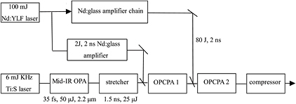
Figure 1. Schematic of the 100-TW-level mid-infrared laser system.
Download figure:
Standard image High-resolution imageThe OPCPA process can be simulated by numerically solving the coupled wave equations assuming perfect phase matching ( ). The coupled wave equations are as follows:


Here,  are the signal, idler, and pump field, respectively. The second order nonlinear coefficients are given by:
  , where
  is the wavelengths of the signal, pump, and idler field, and
  is the refractive index of the nonlinear crystal at these wavelengths. A split-step Fourier transform algorithm is adopted to solve equations (1)–(3). In the numerical simulation, we assumed the OPCPA pump pulses have a flat-top temporal shape with 2 ns pulse duration and uniform spatial profile. The pump intensity is set to be 1 GW
  in two-stage OPCPAs, which is well below the damage threshold of the
  crystal. The pump beam diameters in the first and second-stage OPCPA are 11.2 mm and 70 mm, respectively.
The lengths of the nonlinear crystal play an important role in the OPCPA performance. In general, a too short nonlinear crystal will lead to low conversion efficiency and narrow signal pulse spectrum, while a too long nonlinear crystal will result in back conversion from the signal to the pump. Thus, it is necessary to choose the appropriate nonlinear crystal length for maximizing the conversion efficiency and signal spectral width. Numerical simulation makes it possible to monitor pulse evolution along the nonlinear crystal, thus helping to choose the optimal nonlinear crystal length. In the simulation, we optimized the crystal length for the OPCPAs.
The phase-matching bandwidth for an OPCPA is in first order inversely proportional to the group velocity mismatching between the signal and idler [19]. Broadband amplification can be achieved while adopting a non-collinear OPCPA geometry, in which group the velocity mismatching is diminishing. In the simulation, we employ a non-collinear OPCPA geometry to eliminate the group velocity mismatching. Meanwhile, a non-collinear OPCPA geometry can benefit to spatially separate the signal and idler beam in the near-degenerate case.
For the mid-infrared OPCPA system, the choosing of the signal wavelength is firstly considered to achieve maximum conversion efficiency and signal spectrum bandwidth. For a fixed pumping laser with a pumping energy of 80 J at 1054 nm, we have numerically simulated the output performances with different signal wavelengths, as listed in table 1. The variation of the signal wavelength significantly affects the signal bandwidth and conversion efficiency. The signal pulse energy and spectral bandwidth decrease gradually as the signal wavelength increases from 2200 nm to 4000 nm, which consequently leads to the decrease in the peak power after recompression for longer wavelengths. The conversion efficiency and signal spectral bandwidth decrease at a longer wavelength, which is mainly attributed to two aspects. Firstly, the efficiency of the energy conversion from the pump to the signal is proportional to  and hence is smaller for longer signal wavelengths. Secondly, the group-velocity dispersion of the signal in
  become greater as the signal wavelength increases, which reduces the phase-matching bandwidth and conversion efficiency at a longer signal wavelength [19]. For narrow phase matching bandwidth, the signal pulse edge cannot effectively amplified, which results in a decrease in the OPCPA conversion efficiency.
Table 1. The OPCPA output performance for different signal wavelength.
| Signal wavelength (nm) | Amplified signal bandwidth (THz) | Amplified signal pulse energy (J) | Dechirped signal pulse duration (fs) | Peak power (TW) (70% compressor efficiency) |
|---|---|---|---|---|
| 2200 | 16.6 | 36.9 | 53 | 483.8 |
| 2400 | 15 | 31.4 | 56 | 392.4 |
| 2600 | 14.4 | 27.3 | 58 | 329.2 |
| 2800 | 12.8 | 22.8 | 64 | 249.7 |
| 3000 | 10.8 | 17.9 | 75 | 167.9 |
| 3200 | 9.7 | 14.8 | 85 | 122.4 |
| 3400 | 8.3 | 12.3 | 97 | 87.9 |
| 3600 | 7.2 | 10 | 114 | 61.5 |
| 3800 | 6.4 | 8.4 | 128 | 45.9 |
| 4000 | 5.5 | 7 | 148 | 33.3 |
Figure 2 displays the output results containing normalized pulse durations and peak powers after compressor as a function of signal wavelength. We clearly see that the output results at 2200 nm are superior to those at longer wavelengths. Therefore, the signal wavelength of 2200 nm is chosen in our OPCPA system.
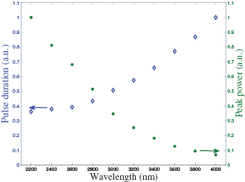
Figure 2. The output results after compressor for different signal wavelengths.
Download figure:
Standard image High-resolution image3. Simulation results and discussion
For the chosen signal wavelength of 2200 nm, we design and optimize the two-stage OPCPA system by numerical simulation. The optimal nonlinear crystal lengths are 21 mm in the first-stage OPCPA and 11 mm in the second-stage OPCPA for maximizing the OPCPA conversion efficiency and signal spectrum bandwidth. Meanwhile, a cross angle of 1. between the signal and pump beams is used to eliminate the group velocity mismatching between the signal and idler pulses. The other parameters are showed in table 2.
Table 2. The parameters of the two-stage OPCPA system.
OPCPA 1  type I (ooe) type I (ooe) |
OPCPA 2  type I (ooe) type I (ooe) |
|
|---|---|---|
| Pump pulse energy | 2 J | 80 J |
| Pump beam diameter | 11.2 mm | 70 mm |
| Pump pulse width | 2 ns | 2 ns |
| Pump fluence | 1 GW  |
1 GW  |
| Pump wavelength | 1054 nm | 1054 nm |
| Signal energy input | 25  J J |
0.86 J |
| Signal beam diameter | 11.2 mm | 70 mm |
| Input signal pulse duration | 1.5 ns | 2 ns |
| Crystal length | 21 mm | 11 mm |
(signal/pump) |
1.2 deg | 1.2 deg |
(pump/optical axis) |
45.5 deg | 45.5 deg |
(signal/idler) |
2.3 deg | 2.3 deg |
| Signal wavelength | 2200 nm | 2200 nm |
The output results from the first-stage and second-stage OPCPAs are showed in figure 3. In the first-stage OPCPA, the seeding signal pulse has a pulse energy of 25  J and a pulse width of 1.5 ns with a bandwidth of 12.6 THz. The pump pulse energy is 2 J. Through the first-stage OPCPA, the signal pulse energy is amplified to 0.86 J and the signal pulse width becomes
  2 ns (figure 3(a)). The amplified signal pulse spectrum is broadened to 16.6 THz due to a significant amplification of signal pulse edges (figure 3(b)). The output signal pulse from the first-stage OPCPA serves as the seeding signal pulse of the second-stage OPCPA. In the second-stage OPCPA, the pump pulse energy is 80 J. Through the second-stage OPCPA, the signal pulse energy is amplified to 36.9 J. The amplifier signal pulse has a spectral width of 16.6 THz with a flat-top spectral profile. After dechirping with the grating compressor, the amplified signal pulse from the second-stage OPCPA can be recompressed to be 53 fs (figure 4). Assuming that the grating compressor has a transmission of 70%, the peak power of the compressed signal pulse can reach up to 483.8 TW.
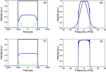
Figure 3. Simulation results: (a) pulse profiles of input pump pulse (black solid line), residual pump pulse (green solid line), and output signal pulse (blue solid line) in first-stage OPCPA. (b) Spectra of the seeding pulse (black line) and the amplified signal pulse (blue line) in first-stage OPCPA. (c) Pulse profiles of input pump pulse (black solid line), residual pump pulse (green solid line), and output signal pulse (blue solid line) in the second-stage OPCPA. (d) Spectrum of the amplified signal pulse (blue line) in the second-stage OPCPA.
Download figure:
Standard image High-resolution image
Figure 4. The temporal profile of the output signal pulse after recompression with its residual phase.
Download figure:
Standard image High-resolution imageThe timing jitter between the pump and signal pulses is generally an important factor for OPCPA performance. We have numerically simulated the influence of the timing jitter to the OPCPA system, and these simulation results can be used to define the requirements on the tolerable jitter level of the OPCPA system. In the simulation, a same time delay between the pump and signal is assumed in the first-stage and second-stage OPCPA, and positive (negative) temporal offset means the signal pulse is ahead of (lagging behind) the pump pulse. As shown in figure 5(a), both the positive and negative temporal offsets result in a broadening of the compressed pulse duration and a decreasing of the signal pulse peak power. Actually, the time jitter will degrade the OPCPA performance. The signal pulse peak power decreases to 40% with  ps time jitter and just decreases to 90% with
  ps time jitter. A small timing jitter does not seriously affect the OPCPA performance due to a flat-top pumping pulse temporal profile. In our case, the time jitter should be below
  50 ps for controlling the peak power fluctuation below 5%.

Figure 5. (a) The signal pulse duration and peak power after compression depend on the temporal interval between signal and pump pulses; (b) the output chirped pulse energy and the peak power after compressor variation with pump intensity fluctuation.
Download figure:
Standard image High-resolution image
The pump intensity fluctuation also plays an important role in OPCPA performance. We also simulate the effect of pump intensity fluctuation on signal pulse energy and the signal peak power after the compressor. While the pump intensity is below 0.9 GW  , the signal pulse energy and peak power sharply decrease. To control the signal peak power fluctuation below 5%, the pump intensity fluctuation should be less than 10%.
4. Practical aspects of the 100-terawatt-level mid-infrared laser design
The temporal and spatial profile of the pump laser is the key factor for achieving high OPCPA conversion efficiency. In general, pump pulses with flat-top temporal and spatial profiles are adopted in high-efficiency OPCPA [20]. In our case, the output seeding pulses from the Nd:YLF laser (figure 1) can be arbitrarily temporally shaped, which benefits obtaining a flat-top pulse profile after amplifying by Nd:glass amplifier chains. On the other hand, a liquid-crystal spatial optical modulator can be adopted to actively control the beam spatial profile of the Nd:YLF output laser, thus a nearly flat-top spatial profile of the pumping beam can be realized after amplifying. Adopting a non-collinear interaction geometry of the OPCPA can also lead to beam walkoff. In the first-stage and second-stage OPCPAs, the spatial walk-offs between the pump and the signal are 0.44 mm and 0.23 mm, respectively. Taking into account the large pump beam diameters adopted (11.2 mm pump beam diameter in the first-stage OPCPA and 70 mm pump beam diameter in the second-stage OPCPA), the beam walk-off can be safely neglected in the simulation.
The pulse stretcher and compressor are key components in the 100-terawatt-level mid-infrared laser system. It is crucial to consider how much dispersion can be provided by the stretcher and compressor, and whether the compressor is matched with the stretcher. An offner-type grating stretcher can be used to stretch the seeding signal pulse. The stretcher consists of mid-infrared grating, a concave mirror and convex mirror, and a roof mirror. The mid-infrared grating has a groove density of 600 lines per millimeter. The radii of curvature of the concave mirror and convex mirror are 1000 mm and −500 mm, respectively. A roof mirror is used to guide the signal seeding pulse to pass the stretcher for the second time and eliminate the spatial chirp. A mid-infrared grating with a size of  mm is enough to stretch the mid-infrared seeding pulse from 35 fs to 1.5 ns.
A Treacy-type compressor can be used to compress the amplified signal pulse by the OPCPAs (section 3). The compressor with a grating distance of  1.2 m is completely matched with the stretcher, thus well compensating for the second-order and third-order dispersion provided by the stretcher. The compressor consists of four pieces of mid-infrared gratings with a size of
  mm, a groove density of 600 line
  , and a diffraction efficiency of 92%. The signal beam is expanded to 240 mm in diameter with a beam expander before pulse compression. The largest pulse fluence on the compressor grating is about 0.06 J
  (on the first and fourth grating), which is far below the damage threshold of the gold-coated gratings (0.3 J
  ). Considering a
  70% compressor efficiency, more than a 100 TW mid-infrared laser at 2.2
  m can be generated (table 1).
5. Conclusion
We have theoretically designed a 100-terawatt-level mid-infrared laser system based on an OPCPA scheme. Our simulation results show it is feasible to generate a 100-TW-level mid-infrared laser by using a two-stage  -based OPCPA. Detailed works including OPCPA performance with different mid-infrared signal wavelengths and the impact of timing jitter and pump intensity fluctuation on the output results have been carried out in this paper. The theoretical scheme of a 100-terawatt-level mid-infrared laser system in this paper will provide a guideline for the construction of a high-intensity mid-infrared experiment system.
Acknowledgments
The work is partially supported by the Shanghai Excellent Academic Leader Project (Grant No. 15XD1502100), National Natural Science Foundation of China (Grant No. 11421064) and the National Basic Research Program of China (Grant No. 2013CBA01505).