Abstract
Objective. Among the currently available neural interface devices, there has been a need for a penetrating electrode array with a high electrode-count and high electrode-density (the number of electrodes/mm2) that can be used for electrophysiological studies of sub-millimeter neuroanatomical structures. We have developed such a penetrating microelectrode array with both a high electrode-density (25 electrodes/mm2) and high electrode-count (up to 96 electrodes) for small nervous system structures, based on the existing Utah Slanted Electrode Array (USEA). Such high electrode-density arrays are expected to provide greater access to nerve fibers than the conventionally spaced USEA especially in small diameter nerves. Approach. One concern for such high density microelectrode arrays is that they may cause a nerve crush-type injury upon implantation. We evaluated this possibility during acute (<10 h) in vivo experiments with electrode arrays implanted into small diameter peripheral nerves of anesthetized rats (sciatic nerve) and cats (pudendal nerve). Main results. Successful intrafascicular implantation and viable nerve function was demonstrated via microstimulation, single-unit recordings and histological analysis. Measurements of the electrode impedances and quantified electrode dimensions demonstrated fabrication quality. The results of these experiments show that such high density neural interfaces can be implanted acutely into neural tissue without causing a complete nerve crush injury, while mediating intrafascicular access to fibers in small diameter peripheral nerves. Significance. This new penetrating microelectrode array has characteristics un-matched by other neural interface devices currently available for peripheral nervous system neurophysiological research.
Export citation and abstract BibTeX RIS

Content from this work may be used under the terms of the Creative Commons Attribution-NonCommercial-ShareAlike 3.0 licence. Any further distribution of this work must maintain attribution to the author(s) and the title of the work, journal citation and DOI.
1. Introduction
A variety of neural interfaces have been developed over the last few decades, which have provided researchers and clinicians with an ever-expanding repertoire of design choices to meet their research or clinical goals [1–7]. High-count microelectrode arrays have proven useful in basic physiology research [8], and for clinical applications such as the restoration of function in people with nervous system injury [9] or stroke [10]. In order to determine which device to use for a given physiological experiment or clinical application, the neural interface must meet the needs of both the desired physiological outcome and the constraints applied by the targeted neuroanatomy. Current peripheral nerve interfaces have electrodes that vary in their number of contacts, which can be separated by hundreds of micrometers [2, 4, 5, 11–13] or several millimeters [3, 7, 14]. Many of the devices have a low number of electrodes (<10) that are implanted interfascicularly (e.g. slowly penetrating interfascicular electrode, SPINE [6]), intrafascicularly (e.g. longitudinal intrafascicular electrode, LIFE [15]), or epineurally (e.g. flat interface nerve electrode, FINE [7]). Recent penetrating neural interface applications are requiring a greater number of electrodes (>60) to achieve complex neuromodulation [9, 10, 16] or neurophysiological [8] goals.
One design feature of penetrating neural interfaces that greatly impacts their application is electrode-density, or the number of electrodes per mm2. Some neural interface devices have been fabricated with high electrode densities; however, their designs have limited the use of these arrays to specific central nervous system structures, such as cortical grey matter (6.25 electrodes/mm2 [12, 13]; >150 electrodes/mm2 [17, 18]) or hippocampal slices (<11 electrodes/mm2 [19]). Other high electrode density devices include non-penetrating electrode arrays [20], which will not be discussed herein. Currently, there is one high electrode-density (6.25 electrodes/mm2), high electrode-count (96 electrodes) penetrating device available for neuromodulation of large structures (> 4 mm) in the peripheral nervous system [1]. However, penetrating electrode arrays with higher densities have been needed to expand neurophysiology research and to investigate future clinical applications in sub-millimeter neuroanatomical structures, such as small diameter peripheral nerves or ganglia (e.g. the 1 mm cat pudendal nerve). Moreover, higher density microelectrode arrays would improve the access to closely spaced individual or sub-populations of neurons and/or nerve fibers in order to investigate the mechanisms underlying more complex spatial neural interactions.
We have recently developed a penetrating electrode array with a 25 electrodes/mm2 density (called the High-Density Utah Slanted Electrode Array or HD-USEA). The grid of electrodes used in these studies had graded electrode lengths ranging from 300 to 800 µm with neighboring electrodes separated by 200 µm. We have shown that the production of a defined geometric surface area (GSA) of the electrode tips was possible using either an oxygen plasma etching technique [1, 21] or by excimer laser ablation [22]. This paper describes the fabrication techniques used for the production of these arrays as well as the results of in vitro and in vivo electrode characterizations.
One of the main concerns regarding the use of penetrating microelectrode arrays that have such high electrode densities is that a nerve crush injury may result from their implantation. Physiological and histological evaluations showed no evidence of complete nerve trunk injury [23] after acute (<10 h) implantation of HD-USEAs. We observed that electrical stimulation of rat sciatic nerve fibers delivered via individual HD-USEA electrodes could selectively evoke hind limb muscle twitches. In the same rat preparations, we were also able to record afferent neuronal activity via individual electrodes that was evoked by tactile and proprioceptive stimuli. Histological analysis of the implantation sites verified that multiple HD-USEA electrodes penetrated into the individual fascicles (<500 µm in diameter) of both the rat sciatic and feline pudendal nerves with little or no evidence of nerve fiber compression around the electrode tips. Collectively, these results show that HD-USEAs are safe and effective for acute neurophysiology studies (we have yet to investigate their use in chronic experimentation). The architecture of this device makes it a unique and useful addition to the neural interfaces currently available, as it provides unprecedented nerve fiber access in sub-millimeter structures outside the central nervous system.
2. Methods
2.1. Device fabrication
High-density electrode arrays were fabricated using techniques that were previously described [13, 24–26]. In brief, fabrication of these devices proceeded in the following steps (described subsequently): back-side dicing, glassing, back-side metallization, front-side dicing, wet etching, dicing of individual arrays from the wafer, tip metallization, parylene-C deposition, tip de-insulation, and finally, wire-bonding to a connector. The devices used in this study were fabricated from 2 mm thick boron-doped (p-type) single crystal silicon wafers (76.2 mm diameter) with high boron concentrations (resistivity of silicon wafers <0.0025 Ω cm). The fabrication procedures were designed to cover the entire wafer with sets of 400 electrodes (sets of 20 × 20 square grids). The initial back-side dicing—to form a square grid of kerfs—was done using a Disco dicing saw (DAD-3220) with a 50 µm thick resin blade (Semicon - FSN1600508). The resulting kerfs had a pitch of 200 µm and a depth of 500 µm. These kerfs were later filled with glass to electrically isolate the electrodes [25, 26]. Metalized bond pads for wire-bonding to the electrodes were formed on the squares between the kerfs using standard photolithographic techniques. Bondpads were sputter deposited as individual layers of titanium (Ti), platinum (Pt), titanium tungsten (TiW), then Pt, with respective thicknesses of 100/150/550/350 nm (1150 ± 100 nm total thickness).
The front side of the wafer was then diced in one direction to form sequences of 20 steps. The steps were subsequently diced in two orthogonal directions to produce the high aspect-ratio columns that would become electrodes following the etching procedure. This dicing step was also done using the Disco dicing saw, but with a 70 µm nickel (Ni) bound blade with a 3 µm diamond mesh size (NBC-Z 1050). The post-dicing dimensions of these columns were approximately 110 × 110 µm with lengths that ranged from 200 to 1500 µm in each 20 × 20 array. The wafer was then cut into quarters to facilitate etching. A two-step wet acid etching process using a homogeneous mixture of 95% HNO3 and 5% HF was used to produce the final shape of the electrodes in the array. The first and second etching steps were performed on each quarter of the wafer for 3 min (in an agitated solution) and 3.45 min (in a non-agitated solution), respectively. The wafer was then diced into individual 20 × 20 arrays and prepared for tip metallization by pushing the electrode shanks through a thin square of aluminum foil (to protect the bottom of the electrode shanks from becoming metalized). A film stack of Ti/IrOx (100/500 nm) was sputter deposited using pulsed DC at a 10 mTorr process pressure and at a power of 90 and 100 W for the Ti and IrOx films, respectively. These sputtered Ti and iridium oxide films (SIROF) were deposited for 5 and 40 min, respectively, with gas flows of 150 sccm Ar for the Ti, then 100 sccm each of Ar and O2 for the IrOx deposition.
Annealing of the metalized tips and parylene-C coating (6 µm thick) of the shanks was carried out as previously described [22]. Arrays were de-insulated with either an oxygen plasma etch of aluminum-foil-masked electrode shanks (March Plasmod, March Plasma Systems, Inc.; 150 W, 400 mTorr, n = three arrays) [13, 27] or with an excimer laser (200 pulses, 248 nm wavelength, 1440 mJ cm–2, n = one array) [22]. The carbon debris generated by the laser ablation was removed by a shorter (2 min) oxygen plasma etch using the parameters described above. One wafer yields approximately 20 arrays that do not have any broken electrodes. The 20 × 20 electrode arrays were then custom diced and a subset of these electrode arrays were wire-bonded using insulated wire (Isonel Au:Pd (with 2% Pd), Kanthal) to a Tucker-Davis Technologies (TDT) 96-pin ZIF-Clip connector. Although 10 × 10 arrays were built using these processes, the final wired electrode arrays used herein consisted of 4 or 5 by 10 electrodes with targeted lengths from 300 to 800 µm along the long axis of the array with 2–4 electrodes wired as reference electrodes. This number of electrodes was chosen to best fit the dimensions of the peripheral nerves tested in this work, but up to 96 electrodes could be wire-bonded for use in other nerve structures. An external reference wire (5 mm Pt, PTFE insulated) was also bonded to the TDT reference pads.
2.2. In vitro and in vivo HD-USEA characterization
Impedance testing and scanning electron microscopy (SEM) were used to characterize the HD-USEAs. Impedances were measured using an automated impedance tester as described previously [28]. In brief, the impedance of each electrode was measured with a 1 kHz, 10 mV sine wave [28]. Impedance tests were performed with the array, the driving electrode and the sensing electrode placed in a dish of sterile 0.9% normal saline. Impedances were tested over the course of 2–3 days. In vivo impedance testing was also performed after implantation of the arrays. The geometric surface area (GSA) of the electrode tips was calculated for the electrodes that were de-insulated via plasma etching and laser ablation. The surface area of the tips was approximated using the area of a cone [29], and the values for tip height and radius were determined from SEMs that included >15 tips/image. Tips without any insulation removed were excluded from the calculations (<5 tips per image). The diameter of electrodes across ten devices were determined via optical microscopy by measuring diameters at 20%, 50% and 90% of the electrode length measured from the electrode tip.
2.3. Surgical and experimental procedures for in vivo validation of HD-USEA functionality
All procedures were approved by the Institutional Animal Care and Use Committee of the University of Utah. Sprague-Dawley rats (350–500 g) were used for the sciatic nerve preparations, and anesthesia was induced using either Isoflurane (2–5% gas in an induction chamber) or a mixture of Xylazine (7.5 mg/kg IP) and Ketamine (65 mg/kg IP). Felines were used for the pudendal nerve preparations, and anesthesia was induced using Telazol (9–12 mg/kg IM) or Ketamine (10–20 mg/kg IM). Anesthesia was maintained with Isoflurane (1–2% gas) for both rats and felines, with the addition of α-Chloralose (30 mg/kg initial dosage, 15 mg/kg maintenance dosage, IV) for felines. Vital signs (heart rate, blood oxygen saturation and rectal temperature) were monitored and recorded to assess the depth of anesthesia and condition of the animal.
The surgical procedures followed those previously described for exposing the sciatic [1, 30] and pudendal nerves [31]. The electrode arrays were inserted using a high-velocity pneumatic pulse insertion technique [32]. Electrical currents were injected via HD-USEA electrodes using a custom-built 1100-channel stimulator [33]. Constant-voltage, monophasic cathodic stimuli with varying amplitudes (−2 to −3 V) and pulse-width durations (0.2 to 1024 µs) were used. A custom built program (MATLAB, MathWorks) was used to control stimulation via individual electrodes [34, 35]. Electromyography (EMG) wires (California Fine Wire Co., Model M146240) were custom made as previously described [31]. Two EMG wires were inserted into each targeted muscle in the rat hind limb in order to record bipolar EMG responses to electrical stimulation. EMG responses were normalized to maximal muscle twitches evoked by either stimulating all electrodes simultaneously or by delivering stimulation through a single microelectrode. Electrodes that activated only flexor or extensor muscles at greater than 0.5 of the normalized EMG response were considered to be selective. Data collection was done using a Cerebus data acquisition system (Blackrock Microsystems, Inc.). In the rat preparations, recordings were taken from all wired electrodes while applying various mechanical stimuli to the lower limb. These stimuli included brushing areas of the foot and rotating the foot around the ankle joint. Signal-to-noise ratios (SNR) were determined by dividing the amplitude of the average waveform by two times the standard deviation of the waveforms [36]. Data analysis was carried out using MATLAB and Microsoft Excel.
Electrode arrays were acutely implanted (1–10 h) into small diameter peripheral nerves. Rat preparations were used for histology and physiology, while the feline preparations were used for histology only (physiology of the pudendal nerve is beyond the scope of this work). After the animals were sacrificed, the exposed nerve containing the HD-USEA implant site was soaked in 4% paraformaldehyde for 30 min, and the arrays were then explanted. Nerves were excised from the animal and stored in 4% paraformaldehyde for 24 h, then rinsed and stored in 1% phosphate buffer solution with 0.01% sodium azide. Tissue was then stained with 1–2% OsO4 in a 0.1M sodium cacodylate buffer, dehydrated in graded concentrations of ethanol, cleared with propylene oxide and embedded in Embed 812 (Epon, Electron Microscopy Science). Serial 0.5–0.6 µm semithin sections (Ultracut EMUC6, Leica) were stained and examined with an Olympus AX70 Microscope. Scatic nerves were stained with toluidine blue and pudendal nerves were stained with thionin and acridine orange (Sigma-Aldrich). Sciatic nerve image fields were digitized using a high-resolution Olympus DP12 camera. Pudendal nerve images were obtained using ImagePro Plus 4.0 (MediaCybernetics) and a color CCD camera (Photometrics) attached to a Nikon E600 microscope. The whole pudendal nerve images were obtained at 200 × final magnification, while fascicle images were obtained at 1000× final magnification. For the pudendal nerve imaging, serial overlapping images were taken over the entire nerve or fascicle. Serial images were reconstructed to form a mosaic image using the photomerge command in Adobe Photoshop CS.
3. Results
3.1. Precision of HD-USEA device fabrication
Figure 1 shows a scanning electrode micrograph of the new HD-USEA device located next to a conventional USEA. The desired GSA of the exposed SIROF electrode tips was achieved by oxygen plasma etching and laser ablation techniques. The average GSA of electrode tips de-insulated with the oxygen plasma etching (figure 1(b)) and laser ablation (figure 1(c)) methods were 4543 ± 526 µm2 (mean ± sd; n = 17 tips from one device) and 473 ± 365 µm2 (n = 22 tips from one device), respectively. The in vitro mean tip impedances of the electrodes de-insulated by laser (n = one array) and plasma etching (n = three arrays) were 440 ± 340 and 179 ± 216 (mean ± sd) kΩ, respectively. The device de-insulated using the excimer laser technique had a large drop in mean tip impedance to 232 ± 150 kΩ when measured in vivo.
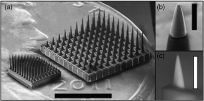
Figure 1. The High-Density Utah Slanted Electrode Array (HD-USEA). (a) A scanning electron microscopy (SEM) image of the conventionally spaced USEA (right) and the new HD-USEA (left) located atop a US penny (scale bar = 3 mm). The inset SEM images were taken of HD-USEA tips that have the biocompatible parylene-C insulation removed using (b) an oxygen plasma etching technique (geometric surface area (GSA) = 4367 µm2; scale bar = 50 µm) and (c) a novel hybrid excimer laser and plasma etching technique (GSA = 297 µm2; scale bar = 25 µm).
Download figure:
Standard image High-resolution imageThe quality of the manufacturing techniques used was assessed by comparing the electrode dimensions [13] from ten different non-wire-bonded HD-USEAs produced from the same silicon wafer (figure 2). The diameter of the electrodes along the length of each shaft was measured at three different points for each electrode and across ten devices (figure 2; four rows of electrodes are shown for clarity). The average lengths of the longest and shortest electrodes measured from these ten devices ranged from 884 ± 39 to 310 ± 60 µm, respectively (averages were calculated from all ten electrode rows). The quality and reproducibility of HD-USEAs is comparable to that of the conventional arrays currently being manufactured.

Figure 2. Structural variability of ten HD-USEA devices. The diameters of four electrodes from ten different HD-USEA devices was measured at 20%, 50%, and 90% the distance from the tip down the shaft of the electrode (from Rows 1, 4, 7 and 10; short to long electrodes). Diameters and electrode lengths are shown on the left and right ordinates, respectively. Bars represent the standard deviation for each set of measured diameters and lengths.
Download figure:
Standard image High-resolution image3.2. Selective recordings from afferent nerve fibers in rat sciatic nerve
In order to learn if such high electrode density arrays could be implanted into a nerve and subsequently used for neurophysiological research, we recorded the neuronal response to different tactile or proprioceptive stimuli in three rats with sciatic nerves acutely implanted with HD-USEAs. In each experiment, there were >25 electrodes out of the 48 wired electrodes that were able to record either single unit or multiunit waveforms. In each preparation, there were neural units that fired spontaneously, and different neural units that could be selectively driven by tactile or proprioceptive stimuli. Figure 3 shows an example of two neural units that were recorded via two different HD-USEA microelectrodes on one implanted device and that were driven specifically by dorsiflexion (figure 3(a), electrode 21) or by plantarflexion (figure 3(b), electrode 14) of the ankle, respectively. The mean SNR for all three preparations across all recording channels was >4.
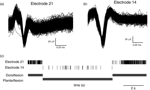
Figure 3. Neural units recorded in rat sciatic nerve from two HD-USEA electrodes on a single implanted array. (a) 968 waveforms show the summation of the responses from two units to dorsiflexion of the foot around the ankle joint recorded by electrode 21 (SNR = 5.9). (b) 1416 waveforms show a unit recorded on electrode 14 that was driven by plantarflexion (SNR = 10.8). (c) The neural events recorded by electrodes 21 (top) and 14 (bottom) during both dorsiflexion and plantarflexion (shown below raster plot). Note that electrode 21 recorded neural responses only during dorsiflexion, while electrode 14 recorded responses only during plantarflexion.
Download figure:
Standard image High-resolution image3.3. Selective motor fiber activation achieved by electrical stimulation of rat sciatic nerve
Delivering voltage-controlled stimulation via individual electrodes on the implanted HD-USEA evoked selective muscle twitches in the ankle flexor and extensor muscles. In all three rat preparations, there were 15 ± 6 and 17 ± 8 (mean ± sd) electrodes that selectively evoked ankle flexion and extension, respectively. Figure 4 shows selective muscle activation using recruitment curves generated in the ankle flexor muscle—tibialis anterior (TA)—and the ankle extensor muscles—lateral gastrocnemius (LG), medial gastrocnemius (MG) and soleius (S)—by cathodic stimulation (−2V, up to 1024 µs pulse-widths) delivered via two different HD-USEA microelectrodes on one implanted device. This selective activation of flexor versus extensor muscles was achieved by delivering stimulation via two catercornered electrodes with an approximate tip-to-tip separation of 208 µm.
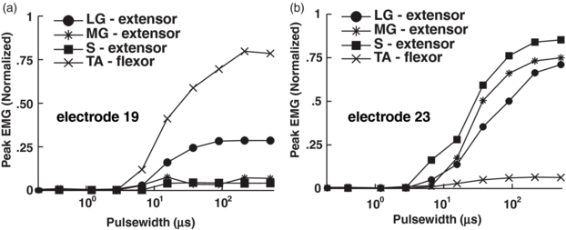
Figure 4. Selective ankle flexor and extensor muscle contractions evoked with stimulation in rat sciatic nerve. Normalized EMG peak amplitude was recorded in response to increasing stimulation amplitude (via increasing pulse-width) delivered via single electrodes on HD-USEA. (a) Stimulation delivered via HD-USEA electrode 19 evoked selective contractions in the ankle flexor muscle, tibialis anterior (TA). (b) Similarly, stimulation delivered via electrode 23 evoked selective contractions in the ankle extensor muscles: lateral gastrocnemius (LG), medial gastrocnemius (MG), and soleus (S).
Download figure:
Standard image High-resolution image3.4. Histological evaluation of HD-USEA implants
A fixed sample of the rat sciatic nerve that was implanted with an HD-USEA is shown in figures 5(a) and (b). The suture in figure 5(a) marks the distal portion of the nerve. The nerve was sectioned through the middle of the implant site. A microscopic cross section of the 1.8 × 0.8 mm nerve shows penetration of the shorter HD-USEA microelectrodes (<400 µm in length) with preservation of the intrafascicular anatomy (epineurial, endoneurial and perineurial) between electrode penetration tracks into the nerve (figure 5(c)). Figures 5(d)–(f) show the microelectrode tracks of several HD-USEA electrodes. Sections taken through the center of an electrode track show no compression of the axons around the electrode tips (figures 5(d) and (e). A section taken adjacent to the center of the electrode track shows no compression of axons around the electrode shank (figure 5(f)).
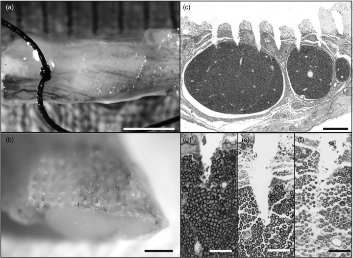
Figure 5. Evaluation of implant site in rat sciatic nerve. (a) and (b) HD-USEA electrode tracks are visible on macroscopic inspection of the nerve (a, scale bar = 2 mm; b, scale bar = 0.5 mm). (c) Microscopic cross section of the nerve shows penetration of a row of shorter length electrodes into the top portion of the rat sciatic nerve fascicles (scale bar = 200 µm). (d)–(f) show a close up of the tips of the short electrodes penetrating into a fascicle. (f) shows a section taken adjacent to an electrode shank. Notice there is no axonal compression around the tips (d)–(e) of the electrodes or around the shanks (f) of the electrodes. (d)–(f) scale bars = 50 µm).
Download figure:
Standard image High-resolution imageFigure 6(a) shows a cross-section of a feline pudendal nerve that was implanted with an HD-USEA. This section was taken from the portion of the nerve that was implanted with longer electrodes (>400 µm in length). As with the sciatic nerve implant, there is preservation of the intrafascicular anatomy in the region between electrode tracks. One electrode was broken prior to implantation and does not penetrate into the fascicular space (track marked with an arrowhead; figure 6(a)).

Figure 6. Cross-section of cat pudendal nerve implanted with HD-USEA for <10 h. (a) Low-resolution image showing penetration of four electrodes into the nerve, three of which penetrated the fascicular space. The far right track (arrowhead) is from an electrode that was broken prior to implantation. The three tracks that penetrate into the endoneurium extend approximately 450–500 µm from the edge of the epineurium to the electrode tips (scale bar = 200 µm). (b) Close up view of an electrode track from (a) (denoted by arrow) showing penetration of the electrode through the epineurium and perineurium into the endoneurial space (scale bar = 100 µm). While substantial loss of fibers in the electrode track is observed, fibers immediately surrounding the track show minimal signs of acute damage. Additionally, no evidence of complete crush injury or nerve compression is observed.
Download figure:
Standard image High-resolution image
4. Discussion
4.1. Array fabrication
We have successfully fabricated 25 electrodes/mm2 penetrating microelectrode arrays with varying length electrodes designed to access nerve fibers that are found at different depths in small peripheral nerves. The electrode proportions, impedances, number of functionally distinct electrodes and SNR of HD-USEAs are comparable to the conventionally spaced Utah electrode arrays [1, 13]. Implantation of the regularly spaced Utah arrays into sub-millimeter structures would result in neural interfaces that have a functionally low-count number of electrodes that could stimulate and record from nerve fibers. For example, implantation of a 5 × 10 conventional array (0.4 mm electrode spacing with lengths from 0.5 to 1.5 mm) into a 1 mm nerve would result in partial coverage with at most only two electrode rows penetrating into the nerve (20 electrodes). Additionally, the shortest electrode row (0.5 mm in length) would be too long to access fibers within the upper half of the nerve and the longest electrodes would pass through the nerve. Thus, as few as 6 electrodes of the conventionally spaced arrays might be functionally implanted into a 1 mm nerve. In contrast, implantation of a 5 × 10 HD-USEA would result in more complete coverage (from 0.2 to 1.0 mm) of the nerve and with a high-count number of electrodes (48 electrodes). For physiological testing of these arrays, we choose to wire-bond two different grids: a 5 × 10 grid of electrodes to custom-fit the size of the rat sciatic nerve (1.2 mm in diameter [37]) and a 4 × 10 grid to custom-fit the feline pudendal nerve (1 mm in diameter [38]).
For the fabrication of these arrays, low resistivity silicon wafers were used to reduce the ohmic contact resistance between the metal-semiconductor interfaces (the metalized tips and bond pads) and produce reliable contacts at lower annealing temperatures. The initial grid of electrodes was made bigger than the required grid to facilitate uniform acid etching of these columns in the middle regions of the 20 × 20 grid. The wet etching times were optimized to produce narrow shanks and rounded electrode tips. Wafers were cut into quarters for the wet etching steps in order to reduce the number of cuts made down from approximately 1000 to 250, which provides more uniform kerfs widths and depths. Analysis of the widths of the electrode shanks at different locations along their lengths across ten electrodes on ten different devices demonstrates the uniformity that was achieved during fabrication of these devices.
Electrode impedances were measured in vitro and in vivo to characterize the quality of the arrays. One concern in development of this device was whether we would have difficulty fabricating arrays with de-insulated tips and electrode impedances in the range needed for stimulation and recording (with SNRs >4), while producing an overall electrode geometry that would meet our anatomical goals (penetrating into fascicles that are 50–200 µm diameter [37, 38]). De-insulation of the HD-USEA microelectrode tips was carried out using two different methods and we assessed the ability of each to produce low and uniform GSAs. De-insulation using the conventional plasma etching technique requires a foil mask to protect the rest of the array from becoming de-insulated. This process can be carried out on individual electrode arrays [13] or—for microelectrode arrays that have uniform electrode lengths—on the wafer scale [24]. De-insulating HD-USEAs using the foil mask and oxygen plasma etching resulted in uniform GSAs (small distribution with standard deviation of 526 µm2), but relatively large areas (4543 µm2). Excimer laser ablation [22] was performed on one HD-USEA in order to decrease the GSA of the electrode tips and thereby, increase the selectivity of neuronal recordings or evoked motor responses. In this work, we used a novel hybrid laser technique that included an additional plasma etching step. The mean GSAs obtained with the laser ablation de-insulation (473 ± 365 µm2) were significantly lower (alpha = 0.05; p = 1.06 × 10⁻²⁶; two-tailed student t-test); however, this technique produced much less uniform tip exposures (larger distribution around the mean) likely due to the manual nature of the process. De-insulation via laser ablation was done manually for each individual electrode; however, future work is aimed at developing an automated process.
The excimer laser ablation technique used in this work required the use of oxygen plasma etching to remove the carbon debris generated by the laser ablation. The carbon debris layer is thinner than the parylene-C layer [22], and thus, we hypothesized that the etching of the carbon debris could be carried out in 2 min without the need of a foil mask. The laser ablation technique (laser spot-size) was optimized for lower-density (6.25 electrodes/mm2) microelectrodes arrays, and more work is needed to optimize the parameters for performing laser ablation on higher-density neural interfaces. The drop in impedance values after in vivo implantation for the laser deinsulated array may have been due to unknown effects of stimulation on impedance values [39]. The mean GSAs for the laser de-insulated electrodes were well within the safe limits established for penetrating microelectrodes (GSA ≤2000 µm2) [29]; however, more work is needed to decrease the GSA of electrodes de-insulated using the foil mask technique.
4.2. In vivo characterization of HD-USEAs
The conventionally spaced, lower density USEA can be implanted both acutely (<1 days) [1] and chronically (>6 months) [40, 41] with insult to the epineurium or perinerium limited to the areas penetrated by the microelectrodes. The main concern for using the newly fabricated high-density arrays of electrodes is that the high-velocity pneumatic pulse insertion [32] of the device could cause a partial or complete nerve crush injury. We were able to record spontaneous and stimulus driven neuronal units on >25 electrodes with an average SNR >4 in all animal preparations, indicating the nerve remained viable for at least the duration of these experiments (<10 h). Importantly, histological analyses of the HD-USEA implant sites showed the nerve axons and fascicles appear to manifest no global damage. Tissue insult was limited to that which was produced by the penetrating electrode tips, similar to implantation of arrays that were four times less dense. If these arrays produced an acute nerve crush injury, rather than a limited penetrating injury, we would have expected to see evidence of traumatic injury to the anatomical structure of the nerve, which may have included: the loss of myelinated axons surrounding the electrodes; the loss of continuity of axons around the electrodes with preserved connective tissue between the electrode tracks; or the complete transection of the nerve [23, 42]. The cross-sections of acutely implanted rat sciatic nerves (n = 2) and a feline pudendal nerve (n = 1) showed no signs of these types of nerve injuries outside the tracks of the penetrating electrodes. Moreover, there was little compression of the nerve fibers around the tips and shanks of the HD-USEA electrodes, as had been previously noted for the conventionally spaced USEAs [1]. Future studies will be needed to assess any chronic damage to the nerve and whether any such damage is followed by nerve regeneration, as in other nerve crush injury studies [42].
We also investigated the degree of selective motor fiber access in the rat sciatic nerve by delivering voltage-controlled stimulation via individual HD-USEA electrodes. In all three rat preparations, we were able to evoke selective contractions of ankle flexor and extensor muscles, and importantly, such selectivity could be achieved in electrodes with a tip-to-tip separation as low as 208 µm between electrodes. One advantage of the use of penetrating microelectrodes is that less current is needed to stimulate nerve fibers once the tips are inside the fascicle. Selective and complete recruitment of rat hind limb muscles was possible by delivering stimulation amplitudes of only −2 V with 50% recruitment of muscle twitches seen in some trials for pulse-widths <100 µs. Lower voltages were not investigated, as this is the lowest limit of the 1100 channel stimulator used in these studies [33].
The devices used in these experiments were designed, in part, to investigate the hypothesis that large numbers of electrodes with 200 µm spacing could penetrate intrafascicularly into peripheral nerves, and that such delicate electrodes would be not damaged (broken) by the epineurium and perineurium or vice versa. Further, experiments were designed to test the hypothesis that 200 µm spacing provided selective access both for stimulation and recording from small diameter neuroanatomical structures. In the rat preparation, selective activation of ankle flexor and extensor muscles was achieved by delivering stimulation via two neighboring electrodes in adjacent rows (≈ tip-to-tip separation of 208 µm). Another concern was that the shortest electrodes would not penetrate into the fascicles. Figure 5 shows that, in fact, the shortest electrodes were able to do so. In addition, we were able to record either single or multiunit waveforms from the 300 µm long electrodes in one animal. We were also able to selectively stimulate flexor or extensor ankle muscles by delivering low amplitude (−2 V, steps of increasing pulse-width of 50 µs) stimulation to the 300 µm length electrodes. Together, these results demonstrate HD-USEAs should provide a useful neural interface for small, delicate nervous system structures where access to nerve fibers and/or cell bodies at depths of 200 µm is needed, such as retinal ganglion cells [43], mitral cells of the rat olfactory bulb [44], or dorsal root ganglion neurons [45].
5. Conclusions
We have developed a novel, high electrode-density (25 electrodes/mm2), high electrode-count (48–96 electrodes) penetrating neural interface, designed for use in stimulation and recording in sub-millimeter neuroanatomical structures, such as small diameter nerves (<2 mm) like the rat sciatic [37], feline pudendal [38], or feline/human cochlear nerves [46]. The results reported herein illustrate that such a delicate architecture can be fabricated consistently, and importantly, that implantation of such high-density electrode arrays does not cause nerve damage, at least on the acute time frame (<10 h) studied here. Furthermore, the HD-USEA provides selective access to the fibers of small diameter peripheral nerves. The high electrode-density array described in this study adds a novel and useful architecture to currently available neural interfaces. Future studies will be needed to assess long-term efficacy and biocompatibility of these arrays for their potential use in clinical applications.
Acknowledgments
This work was supported by the National Science Foundation CBET-1134545, the Spanish National Organization of the Blind and the Ministry of Economy and Competitiveness.