

Abstract
Objective. In this study we present the development and testing in a rat model of the self-opening neural interface (SELINE), a novel flexible peripheral neural interface. Approach. This polyimide-based electrode has a three-dimensional structure that provides an anchorage system to the nerve and confers stability after implant. This geometry has been achieved by means of the plastic deformation of polyimide. Mechanical and electrochemical characterizations have been performed to prove the integrity of the electrode with very good results. Functionality of SELINEs for fascicular stimulation has been tested during in vivo acute experiments in the rat. Chronic implants were made to test the biocompatibility of the device. Main results. Results showed that SELINEs significantly improve mechanical anchorage to the nerve. Stimulation stability is considerably enhanced compared to common planar transversal electrodes and stimulation selectivity is increased for some motor fascicles. Chronic experimental results showed that SELINEs neither produce changes in the fascicular organization of sciatic nerves nor signs of nerve degeneration. Significance. The presented three-dimensional electrode provides an effective anchorage system to the nervous tissue that can improve the stability of the implant for acute and chronic studies.
Export citation and abstract BibTeX RIS
Changes were made to this article on 27 January 2015. Author affiliations were amended.
1. Introduction
Interfacing the peripheral nervous system (PNS) in a selective and stable way represents a challenging goal. A successful neural interface should be able to selectively stimulate or record neural signals from small groups of axons, induce no significant damage to the nerve after the electrode implant, and be stable over time (i.e. high selectivity—low invasiveness—high stability).
During past years, many types of electrodes have been developed to interface the PNS in order to record electrical activity from and/or to stimulate peripheral nerve fibers for different biomedical applications (Navarro et al 2005, Del Valle and Navarro 2012). PNS neural interfaces can be classified depending on nerve invasiveness as extraneural, intraneural, or regenerative. Extraneural interfaces are implanted around a peripheral nerve to stimulate or record large groups of axons at a time thus resulting in poor selectivity. Intraneural electrodes are implanted within a nerve; the intimate contact with different fascicles provides a lower threshold for axonal stimulation, improving the selectivity, and a higher signal-to-noise ratio of recordings. Regenerative interfaces are implanted in a sectioned nerve forced to grow through them.
Among all the available solutions, flexible intra-fascicular electrodes (TIME and tf-LIFE) have shown a good compromise between selectivity and invasiveness (Yoshida et al 2000, Boretius et al 2010). These electrodes succeeded in functionality and biocompatibility studies both in animal models (Lago et al 2007, Badia et al 2011a and 2011b) and in human volunteers (Dhillon et al 2005, Rossini et al 2010, Raspopovic et al 2014). However, despite their excellent experimental results, there are still some issues to solve. Movements of the limbs where the electrode is implanted can produce changes in the position of the active sites within the nerve (Goodall et al 1991), causing unpredictable modifications of the link with nerve fibers. Moreover, the signal-to-noise ratio of recorded signal decreases when the distance between the electrode and the axons increases, due to motion or interposition of scar tissue.
To prevent the above-mentioned problems, a new electrode has been developed as an evolution of LIFE and TIME, the self-opening neural interface (SELINE) (Cutrone et al 2011). This device is conceived to be transversally or obliquely inserted into the nerve, allowing the contemporary stimulation and recording from different fascicles innervating separate peripheral targets. The innovative aspect of this neural interface is its three-dimensional geometry: the electrode has a main body and two lateral wings on each side provided with active sites. Each device has a total of ten active sites. The structure is inserted into the nerve and then gently pulled back, allowing the transversal opening of the wings. Thanks to this working principle, wings can open through the tissue and remain anchored to it. Furthermore, a three-dimensional geometry offers a second dimension for contacting more axons from different sub-fascicles. Previous works from our group demonstrated the feasibility of SELINE approach from a mechanical (Cutrone et al 2011) and technical point of view (Cutrone et al 2013). This paper describes the fabrication methods and the in vitro and in vivo characterization of the SELINE.
2. Materials and methods
2.1. Electrode manufacturing
2.1.1. Microfabrication
The SELINE consists of a loop structure made of a main shaft with two wings per each side. The shaft is 360 μm wide; each wing has a total length of 400 μm and a width of 150 μm. The device has a sensitive area in which active sites (0.0037 mm2) are located. On both sides of the device there are one active site on the main shaft and two active sites on each wing (figure 1(e)). The length of the sensitive area has been designed to fit the diameter of the rat sciatic nerve, however the design can be modified to match different size nerves. Wing shape and electrode geometry are in compliance with the optimized design presented in our previous study (Cutrone et al 2011).
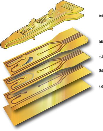
Figure 1. Microfabrication scheme of SELINE (detail of active sites area): (a) spin of PI2611 as substrate layer, (b) deposition and lift off of gold tracks, (c) spin of PI2611 as insulation layer patterned with reactive ion etching, (d) release of the electrode and memorization of curved profile of wings, (e) isometric view of a whole SELINE.
Download figure:
Standard image High-resolution imageThe materials for the SELINE were chosen in order to satisfy biocompatibility, mechanical integrity and electrical efficacy. The insulation of the electrode is made of polyimide, a biocompatible, flexible and stable polymer (Rubehn and Stieglitz 2010); active sites and electrical tracks are made of gold with titanium as adhesion layer. The microfabrication of the device follows standard lithographic techniques used for thin-film electrodes (Boretius et al 2010).
A silicon wafer (Si-Mat, silicon materials) was used as substrate for the development of the electrode layer by layer. Polyimide PI2611 (HDMicroSystem) was spin-coated at 3000 rpm for 30 s (thickness = 6 μm, figure 1(a)). Samples were hard baked in an oven with nitrogen flux at 350 °C for 1 h (Carbolite). Primer, LOL and S1813 (Microposit) were spin-coated on the wafer respectively at 3000 rpm for 30 s, 1000 rpm for 20 s, 4500 rpm for 30 s; samples were exposed to UV (Karl Suss) using a glass photomask (Frontrange Photomask) with an exposure dose of 180 mJ cm−2 (i-line). Samples were developed for 30 s using MF-319, rinsed with DI water and dried. Oxygen plasma (Gambetti) was used to mechanically functionalize the surface and increase the roughness of the layers so enhancing consequent adhesion with the metals (100 W, 15 sccm of O2, 300 mTorr). Titanium and gold were sputtered (Sistec–Leybold) on the samples with a thickness of 20 nm (90 W—1 min) and 250 nm (70 W—3 min) respectively at a vacuum of 4 × 10⁻⁶ Torr. Lift-off was made by plunging the wafer in the photoresist remover with ultrasound for 20 min (figure 1(b)). Samples were washed with DI water and dried. Samples were spin-coated with the second layer of polyimide 6 μm thick (3000 rpm for 20 s) and hard baked at 350 °C for 1 h. Aluminum was thermally evaporated on samples (1 × 10⁻⁶ Torr; 1.3 A) at a thickness of 200 nm (TecnoService). S1813 (Microposit) was spinned on samples (4500 rpm for 30 s) that were subsequently exposed to UV (exposure dose = 180 mJ cm−2, i-line). Development was done for 30 s using MF-319 and samples were rinsed and dried. Wet etching of aluminum was done with a solution of HNO3:H3PO4:HAc:H2O = 4:1:1:4 for 15 min at room temperature. Samples were dry etched with oxygen plasma with a flux of oxygen of 40 sccm at 170 W for 30 min. The aluminum mask was etched away (figure 1(c)). Electrodes were peeled off from the wafer (figure 1(d)).
2.1.2. Strategy for the memorization of wing profile
This design of SELINE provides an anchorage system to the nerve tissue during implantation. A memorization strategy is implemented to switch wings from the normal position (passive configuration) to the open position (active configuration). A mechanical plastic deformation of the electrode was applied to promote wing opening at different amplitudes. Electrodes were attached vertically to a 10 N load cell, while the base was constrained with a press. A panel was located behind the electrode to allow the wings opening on one side only. Electrodes were plastically deformed by applying stress over polyimide yield point (0.6 N mm−2) with a loading velocity of 2 mm min−1. Different angle amplitudes were obtained by regulating the applied stress to the electrode (figures 2(b)–(c)). The setup used for the memorization of wing profile is shown in figure 2(e).

Figure 2. (a) View of the final device: (1) needle and wire, (2) polyimide electrode, (3) silver glue soldering, (4) PCB, (5) connection wires. (b)–(c) View of electrode wings. (d) Front view of electrode contacts. (e) Setup used for the memorization of wing profile: the electrode is attached vertically to a load cell and the base is constrained with a press. A panel was fixed behind the electrode to allow the wing openings on one side only: (1) wing in normal position prior to memorization; (2) wing in open position after memorization.
Download figure:
Standard image High-resolution image2.1.3. Final packaging
Electrodes were rinsed in ethanol and dried. A printed circuit board (PCB) was designed (CadLine) in order to miniaturize the bulk of the whole electrode (length = 8.5 mm; width = 5.7 mm; thickness = 0.2 mm). Insulated wires (Road Runner) were soldered to the PCB. The final part of the electrode with connection pads was attached to the PCB for each side of the electrode with cyanoacrylate glue. Electrical connections between electrode pads and PCB contacts were made by using silver conductive glue (Ablestik-Henkel); followed by thermal treatment in furnace to stabilize and dry silver solderings (2 h at 150 °C). Two-component biocompatible silicone (Silbione-Bluestar Silicones) was applied on the PCB and solderings to avoid contact of the solder material with biological tissue. Polymerization of the silicone for its final stabilization was achieved by thermal treatment at 100 °C for 30 min.
The electrode was folded at its center point and a loop thread attached to a stainless steel needle (STC-6, Ethicon) was placed between the two branches. The two PCBs of the electrode were then glued together. Wires for electrical connections were inserted in a flexible silicone tube and sealed with biocompatible silicone (figure 2(a)).
2.2. Characterization of SELINE
2.2.1. Electrical, electrochemical and mechanical characterization
Ohmic resistance of gold tracks for each active site was measured with a probe tester (Cascade PM5).
Electrochemical impedance spectroscopy was used to measure impedance (Gamry). A three-electrode setup made of a platinum counter electrode, an Ag/AgCl reference electrode and the working electrode was used in 0.9% saline solution. Impedance spectra were characterized between 100 Hz and 100 kHz applying a sinus wave of 5 mV.
Tensile test (Instron) was performed on four samples in order to analyze the mechanical behavior of the electrode. The electrode was folded in its working configuration. The loop of the electrode was attached to a steel hook linked to a load cell of 10 N, whereas the electrode pads were inserted in a ZIF connector and then in a press linked to the Instron. The electrode was stressed until breakage with a loading velocity of 4 mm min−1.
2.2.2. Characterization of the anchoring system of SELINE
A mechanical study was performed in order to evaluate the efficacy of the three-dimensional anchoring system provided by the lateral wings.
Two rat sciatic nerves were harvested, and stored in PBS at −20 °C for one week. Three types of electrodes, with the same geometry but differing in the presence of open, flat, or no wings, were tested:
- SELINE (with memorization): electrodes with open wings in active configuration (seven trials).
- SELINE without memorization: electrodes with flat wings in passive configuration (four trials).
- TIME: electrodes without wings (four trials).
In the experimental setup (figure 3(A)), the nerve was fixed between two presses: on one side, a load cell of 10 N was attached to measure the pre-stress of the nerve. The electrode was constrained to the load cell of the Instron and vertically inserted into the nerve, in compliance with the SELINE way of insertion (see section 1). In order to simulate slippage of the electrode inside the nerve, the electrode was extracted in the same direction but opposite sense of insertion with a loading velocity of 50 mm min−1. Force and displacement were recorded for each trial. Mean values of maximal extraction forces for the three types of electrodes have been calculated and compared.
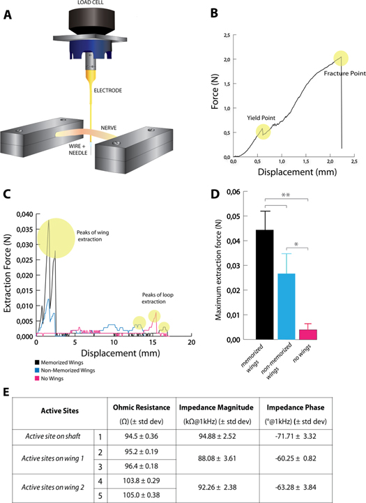
Figure 3. (A) Setup to evaluate the mechanical extraction force of electrodes from rat sciatic nerves. The electrode is first transversally inserted in the nerve and then extracted at a loading velocity of 50 mm min−1. Three different kind of electrodes have been tested (SELINE with memorized wings; SELINE with non-memorized wings and TIME, i.e. SELINE without wings). The three types of electrodes have the same shaft layout and active sites arrangement: they only differ for the presence/memorization of wings. (B) Mechanical tensile test of SELINE: the electrode has been stretched until breakage. Force versus Displacement, yield and fracture points are shown. (C) Overview of extraction force curves of the three different types of tested electrodes: SELINE with memorized wings, SELINE with non-memorized wings, TIME (SELINE without wings). Extraction curves for electrodes with wings (SELINE with/without memorization) show two initial peak forces corresponding to the extraction of the two sets of wings. Peaks are higher in memorized devices than non-memorized ones. No relevant peaks were found for TIME (SELINE without wings) extraction curves. (D) Comparison of maximum extraction force of SELINE, SELINE with non-memorized wings and TIME (SELINE without wings). *p < 0.05, **p < 0.01. Values are given as mean and SEM. (E) Values of Ohmic resistance, impedance magnitude and phase of active sites of SELINEs. Values are given as mean and standard deviation.
Download figure:
Standard image High-resolution image2.3. In vivo tests
2.3.1. Implantation of SELINE
The working principle of the SELINE implantation is divided into three phases (Cutrone et al 2011 and 2013): (i) piercing the nerve with a needle that serves as a guide; (ii) transversal insertion of the electrode across the nerve, and (iii) slight pulling back of the electrode to allow the anchorage of the wings.
In vivo experiments were made on adult Sprague-Dawley rats. All procedures were performed under ketamine and xylacine anesthesia (90/10 mg kg−1 i.p.), following protocols approved by the Ethics Committee of the Universitat Autònoma de Barcelona in accordance with the European Communities Council Directive 2010/63/EU.
Two types of electrodes were used for the comparison: SELINE and TIME. For both types, the mid point of the structure is bent in a V-shape before implantation, and disinfected with 70% ethanol, before implant. The sciatic nerve was surgically exposed at the midthigh and carefully freed from adherences to surrounding tissues. The electrode is inserted with the help of a straight needle attached to a 10–0 loop thread (STC-6, Ethicon); the thread is passed between the two arms of the electrode and pulls the arrow shaped center of the electrode strip (Badia et al 2011a). Electrodes were obliquely inserted, forming a 45° angle with the longitudinal axis of the nerve, across the peroneal and tibial fascicles of the sciatic nerve, proximal to the trifucation of the nerve at the knee (figures 4(A)–(B)). The insertion was monitored under a dissection microscope to ensure the correct placement of the electrode and the adequate positioning of the active sites inside the nerve.

Figure 4. (A) Close view of an implanted SELINE in the rat sciatic nerve. (B) Schematic cross section of an implanted SELINE in position P0 with active sites (AS1-5) crossing the tibial and peroneal fascicles and topography of the rat sciatic nerve [Badia et al 2010]. The electrode is first inserted through the fascicles and then slightly pulled back to facilitate opening of the wings at position P1. (C) Schematic representation of the top view of an implanted electrode: insertion phase; P0, the first tested position (three gold strips outside the nerve); P1, the second tested position (two gold strips outside the nerve).
Download figure:
Standard image High-resolution image2.3.2. Acute electrophysiological tests
To compare the performance of SELINE (S) and TIME (T) for selective neural stimulation, two groups of rats were used. In both groups (S, n = 8; T, n = 4) the intraneural segment of the electrode was inserted as indicated above across the sciatic nerve. After insertion, the electrode active sites were located in a given position inside the nerve fascicles, named position 0 (P0). P0 was defined as the position where the three gold strips on the loop of the electrode are located all outside the nerve (figure 4(C)).
The stimulation protocol was performed using the STIM'3D stimulator (Andreu et al 2009). Monophasic rectangular pulses at 0.5 Hz, with a width of 10 μs and an intensity from 20 to 300 μA were delivered through each one of the electrode sites of the SELINE and TIME against a small stainless steel needle electrode placed near the nerve. Electromyographic (EMG) signals were simultaneously recorded from tibialis anterior (TA), gastrocnemius medialis (GM) and plantar interossei (PL) muscles, which are innervated by different subfascicles of the sciatic nerve (Badia et al 2010). The compound muscle action potentials (CMAPs) were recorded by means of small needle electrodes placed in each muscle, connected to P511 ac amplifiers (Grass), amplified by x100 or x1000, and filtered (5 Hz, 3 kHz). Digital sampling of the signals was made with a PowerLab recording system (PowerLab16SP) at 20 kHz, and fed into Chart software. The amplitude of the CMAP was measured from baseline to peak, and normalized to the maximum CMAP amplitude obtained for each muscle in the experiment. The same protocol was repeated for all the rats and electrodes. Recruitment curves for each active site were plotted.
Measurements of the CMAP amplitude are used to quantify the activation by a specific stimulating condition to a single muscle i, among the set of muscles j (PL, GM, TA). For each active site, a selectivity index (SI) was calculated as the ratio between the normalized CMAP amplitude for that muscle, CMAPni, and the sum of the normalized CMAP amplitudes elicited in the three muscles, CMAPnj (Veraart et al 1993), as (1):
This index ranges from 0 (no activation of the target muscle) to 1 (activation of only the target muscle). Maximum selectivity obtained for each active site for each muscle was calculated for both electrode designs (SELINE and TIME), and the difference between maximum selectivities plotted. Mean values of maximum selectivity, corresponding stimulating current and CMAP amplitudes, as well as threshold current of activation, were compared for SELINE and TIME.
To assess the anchoring effect of SELINE versus TIME design and thus the stability of the implant, both types of electrodes were tested in two different positions: P0 and P1. The imposition of this transversal displacement to the implanted electrode aimed to simulate eventual slippages inside the nerve when external motion occurs. The reproducibility of the two positions was ensured by considering the gold strips marked on the loop of the electrode after implantation. In the P0 position the three gold strips were located just outside the nerve. The P1 position was obtained by slightly pulling the electrode in the opposite sense of the implant, so that only two gold strips were outside the nerve (figure 4(C)). This displacement is equal to 200 μm since the retracted distance was controlled by the 100 μm separated gold printed strips on the electrode ribbon. At P1 position the wings were expected to be more open in the tissue. Once the electrode was repositioned, stimulation through each active site was performed again.
The in vivo stability was evaluated by considering two pivotal aspects of fascicular stimulation: change of threshold current required for activation of each muscle, and change of selectivity for each active site and for each muscle. Two stability indices were introduced: threshold stability index, STth and selectivity stability index, STsel.
The threshold stability index STth considers the change of threshold current from P0 to P1 for each active site and each muscle, and it is described as (2):

where CurrtP0 and CurrtP1 are threshold currents at position P0 and P1 respectively for each active site and each muscle, Currmax is the maximum stimulating current used in the protocol (300 s the maximum stimulating current us stability over imposed movement) and 1 (high stability). In the case a given muscle is activated in one position and not activated in the other position, the stability index was 0.
The selectivity stability index STsel considers the change of maximum selectivity from P0 to P1 for each active site and each muscle and it is described as (3):

where SImaxP0 is the maximum selectivity for each active site and each muscle at position P0, and SImaxP1 is the maximum selectivity for each active site and each muscle at position P1. This value varies between 0 (low stability for selectivity) and 1 (high stability for selectivity). Kolmogorv–Smirnov test was used to statistically evaluate the differences in indices between the two types of electrodes (SELINE and TIME).
2.3.3. Chronic implantation and biocompatibility evaluation
For the study of biocompatibility and safety of chronic in vivo implants, six devices comprised of the polyimide and metal contacts of each SELINE with memorization, SELINE without memorization and TIME, were obliquely implanted, as described in 2.3.2, in the sciatic nerve of adult rats. The sensitive portion of the device was inserted within the tibial and peroneal fascicles, leaving the ribbon part of the device outside and parallel to the nerve (figure 4(A)). Then, the wound was sutured by planes, so that no parts of the electrode were subcutaneous or external to the animal. The PCB connector and wires were not implanted in order to directly assess the effect of the presence of the wings on the nerve, avoiding tethering forces on the electrode. After insertion, the SELINEs were retracted to allow the wings anchoring to the tissue (figure 4(B)). All the animals were followed for 90 d to obtain evidence of possible functional and histological damage induced on the nerve by the implanted electrode. At 10, 30, 60 and 90 d post-implantation, electrophysiological and functional properties of the implanted nerve were evaluated by means of nerve conduction, mechanical algesimetry and walking track tests. The intact contralateral sciatic nerve was used as control.
For nerve conduction tests, rats were anesthetized and the sciatic nerve was stimulated with single electrical pulses (200 μs duration at supramaximal intensity) delivered by monopolar needles placed at the sciatic notch. The CMAP of TA, GM and PL muscles were recorded with monopolar needles inserted into the muscle and recorded with an EMG machine. The latency and amplitude of the CMAPs were measured for each implanted and control nerve (Badia et al 2011a).
The walking track test was carried out to assess locomotion function. The plantar surface of the rat hindpaws was painted with ink and the rat was left to walk along a corridor to a dark cage at one end. Footprints corresponding to the implanted and intact paws were identified, and measurements made to calculate the sciatic functional index (SFI) (De Medinaceli et al 1982) to quantify changes in walking pattern.
The nociceptive responses to mechanical stimuli were evaluated by means of an electronic Von Frey algesimeter (Bioseb). Rats were placed on a wire net platform in plastic chambers. Mechanical nociceptive threshold was measured as the force (in grams) at which rats withdrew the paw in response to the stimulus. The mean of three tests was calculated and expressed as the percentage between the operated and the intact hindlimb of each animal (Casals-Dìaz et al 2009).
Three months after implantation, the sciatic nerves were harvested to evaluate morphological changes in the nerve. Rats were deeply anesthetized and perfused with 4% paraformaldehyde in PBS. The sciatic nerve segment including the electrode implant was harvested and postfixed in the same perfusion solution for 4 h. Then samples were washed and embedded in paraffin. Transverse sections (10 μm thick) were cut, mounted in silane-coated slides, and viewed under light microscopy to assess the electrode–nerve interaction. A nerve segment from 2 mm distal to the electrode implant was postfixed in 3% glutaraldehyde-3% paraformaldehyde in buffer solution, and processed for embedding in epon. Semithin 0.5 μm thick sections were stained with toluidine blue and examined. Measurement of cross-section area of the distal segment of the sciatic nerve, and counts of the number of myelinated nerve fibers were carried out using Image J software (Badia et al 2011a) to assess potential damage leading to axonal degeneration.
Data is presented as mean ± SD or SEM. Results were statistically analyzed by using GraphPad Prism software. One and two-way ANOVA followed by Bonferroni's post hoc test for comparison between groups were used when appropriate. Statistical significance was considered when P values were <0.05.
3. Results
3.1. In vitro results
3.1.1. Manufacturing results
Electrodes were peeled off from the silicon wafer without breaks around the wings by exploiting the low adhesion forces between polyimide and silicon (figure 2(b)). Plastic deformation of the wings allows the memorization of a curved profile in the active configuration. Figure 2(a) shows the final device, whereas panels (b) and (c) show the successful memorization of wing profiles. For in vivo tests, wings have been memorized to form an angle of 30° with the horizontal plane represented by the main shaft of the electrode.
3.1.2. Electrical, electrochemical and mechanical characterization results
Results of electrical and electrochemical characterizations are shown in figure 3(E). Mean Ohmic resistance of the different active sites was between 94 and 105 Ω. These results are in compliance with theoretical evaluation as illustrated in (Cutrone et al 2013). Typical impedance values at 1 kHz were around 90 kΩ.
Regarding mechanical characterization, yield and fracture points were plotted: the maximum force that caused breakage of the electrode (mean ± SD) averaged 2.14 ± 0.23 N (figure 3(B)). Since the value of electrode insertion forces inside nerves is usually in the order of 10 mN (Jensen et al 2007), it is demonstrated that SELINE tolerates well the insertion procedure, avoiding breakage of the wings and of the shaft.
3.1.3. Results of anchoring system characterization
Typical extraction curves for the three electrode types are represented in figure 3(C). Electrodes with wings (memorized and non-memorized) show two peak forces at the beginning of the curve corresponding to the extraction of the two sets of wings. No remarkable peaks were found in the extraction of electrodes without wings. The comparison between extraction forces confirms the efficacy of the anchoring system. Maximum extraction force (figure 3(D) for SELINE with memorized wings was 10 times higher than for TIME (44 mN versus 4 mN). Statistical differences were found between SELINEs and TIMEs (p = 0.0083), SELINEs with non-memorized wings and TIMEs (p = 0.04), but not between SELINE and SELINE with non-memorized wings (p = 0.287).
3.2. In vivo results
3.2.1. Results of acute stimulation tests
Stimulation tests after acute implantation proved that the two types of electrodes (SELINE and TIME) allowed excitation of different axonal subpopulations of the sciatic nerve, thus selectively activating PL, GM and TA muscles through different active sites. At low intensity stimulation, selective activation of one muscle could be detected, due to the close contact of one electrode site with the corresponding muscular nerve fascicle. By increasing the stimulus intensity, the CMAP amplitude increased to reach the maximal value (i.e., activation of the whole muscle); however, the stimulus spread to other surrounding fascicles activating two or all three of the tested muscles. Figure 5(A) shows an example of recruitment curve obtained with a SELINE that produces selective enrollment of the three muscles.

Figure 5. Electrical stimulation was delivered at increasing intensity through each of the ten active sites of the SELINE and TIME electrodes implanted in the sciatic nerve of rats and the CMAP of tibialis anterior (TA), gastrocnemius (GM) and plantar muscles were recorded for assessing stimulation selectivity. (A) Examples of recruitment curves obtained for three active sites of a SELINE showing selective activation of each target muscle. (B) Starting from the recruitment curves, the selectivity index was calculated for the set of three muscles. Maximum values of selectivity index are shown. Values were obtained for each of the ten active sites located on both sides (five active sites on Side 1 and five active sites on Side 2) of SELINE and TIME for each of the three muscles. (C) Plot of the difference of maximum selectivity index (shown in (B)) between SELINE and TIME for each active site and each tested muscle. The variation is positive in case of higher selectivity of SELINE compared to TIME (black). The variation is negative in case of higher selectivity of TIME compared to SELINE (pink). (D) Comparison of the stability index based on threshold current changes between SELINE and TIME for Plantar, Gastrocnemius and Tibialis Anterior muscles; ***p < 0.001. (E) Comparison of stability index based on selectivity changes between SELINE and TIME for Plantar, Gastrocnemius and Tibialis Anterior muscles; ***p < 0.001. Both stability indices showed significantly higher stability of SELINE compared with TIME. (F) Mean values of maximum selectivity for SELINE and TIME for each muscle, corresponding stimulation current and the percentage of CMAP normalized amplitude that they elicited. Values are given as mean and SEM.
Download figure:
Standard image High-resolution imageFor the two types of electrodes, SELINE and TIME, the minimum current of stimulation that elicited a CMAP of at least 5% of the maximal amplitude (threshold current) ranged between 20 and 200 μA with pulses of 10 μs duration. There were no significant differences between threshold mean values of SELINE compared to the TIME (see figure 5(F)).
Differences in selectivity between SELINE and TIME for each active site and muscle are shown in figures 5(B)–(C). For PL muscle, higher selectivity was achieved with TIME (six active sites more selective than SELINE); for TA muscle, similar selectivity was achieved using both electrodes, while for GM muscle, higher selectivity was achieved with SELINE on all active sites. This is confirmed also in figure 5(F) where mean values of maximum selectivity for both electrodes are summarized.
3.2.2. Stability results
Stability indices (STth and STSel) were calculated by comparing results obtained from positions P0 to P1 for SELINE and TIME implants. Both stability indices presented significant differences between the two electrodes for each muscle. Mean values and SEM for stability indices are shown in figures 5(D) and (E) respectively. The threshold stability index STth in SELINEs was 4.8 times higher than in TIMEs for PL and 3.8 times higher for GM muscles, whereas for TA muscle it was 2.7 times higher. The selectivity stability index STsel for SELINEs was 1.7 times higher than for TIMEs for PL, 1.5 times higher for GM muscles and 1.2 for the TA muscle.
3.3. Chronic implantation and biocompatibility results
3.3.1. Electrophysiological and functional results
During the three months of implant, there were no significant changes in the amplitude and latency of the CMAPs recorded during nerve conduction tests performed in animals with SELINE and TIME electrodes, and values were comparable to control ones (figures 6(A)–(D)).

Figure 6. Changes over 90 d follow-up in motor nerve conduction parameters of the three groups with implanted electrodes (TIME, SELINE with and SELINE without memorization) compared to control values. (A), (B) CMAP amplitude, and (C), (D) latency of the CMAP for tibialis anterior and plantar muscles. (E) Plots of the SFI obtained in walking track test. (F) Plots of the values of the algesimetry test expressed as percentage of the contralateral values. *p < 0.05 TIME versus SELINE, ♯p < 0.05 TIME versus SELINE non-memorized. Except for a mild decrease in the SFI at early time points, there were no functional deficits induced by any of the three intraneural electrodes.
Download figure:
Standard image High-resolution imageWalking track measurements did not show variations between the groups with the three tested electrodes from 10 d after the implant until 90 d. The SFI averaged between −20 and 0 during follow-up (figure 6(E)). Slightly low values observed in some rats at 10 and 30 d after implant are attributable to the surgical procedure itself since values returned to normal levels in the three groups at 30 d. The algesimetry test yielded similar values of pain threshold for withdrawal between the implanted and the contralateral sides (figure 6(F)), without evidence of hyperalgesia that might had been induced by nerve compression or injury.
3.3.2. Morphological evaluation of implanted nerves
The electrodes were found in place within the sciatic nerve in all studied animals and no abnormalities were observed during dissection. Light microscopy observations of nerve sections show that the electrode strip crossed the sciatic nerve fascicles and wings of memorized SELINEs were seen open inside the nerve (figures 7(A)–(B)); in contrast there was no consistent observation of open wings in non-memorized SELINEs, indicating that the memorization process is important for the chronic stability of the wings positioning. Transverse sections of the nerve segment distal to the insertion site showed that the fascicular organization and microarchitecture of the implanted nerves was similar to control nerves, and there were no signs of axonal degeneration (figures 7(C)–(H)). The number of myelinated fibers counted in the distal level for tibial and peroneal branches of the sciatic nerve were similar in the three groups of rats with SELINE, SELINE without memorization and TIME implanted, without significant differences with respect to intact sciatic nerves (figure 8). Control and TIME values are in accordance to those previously published (Badia et al 2011a), and from these data it can be concluded that the SELINE design did not cause damage to the implanted nerve.
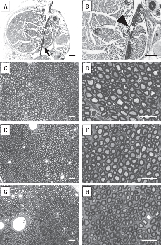
Figure 7. (A) Thick transverse section of the sciatic nerve with an implanted SELINE (arrow). (B) At higher magnification the opened wing (arrowhead) can be seen in close contact with nerve fibers. No gross damage of the nerve fascicle is observed at the implant site. (C)–(H) Semithin transverse sections taken distal to the implanted electrode show normal microstructure of the sciatic nerve. Representative images, taken at 20x (left panels) and 50x (right panels) magnification, of nerve sections distal to TIME (C)–(D), SELINE with non-memorized wings (E)–(F), and SELINE with memorized wings (G)–(H) implants. Scale bar: 100 μm (A)–(B) and 25 μm (C)–(H).
Download figure:
Standard image High-resolution image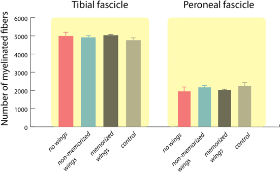
Figure 8. Quantification of the total number of myelinated nerve fibers of the tibial and peroneal fascicles for the three studied groups (no wings, non-memorized wings, memorized wings) compared to intact nerves (control). Values are mean ± SEM.
Download figure:
Standard image High-resolution image
4. Discussion and conclusions
This work presents the manufacturing, in vitro characterization and in vivo testing of an innovative neural interface for the PNS, named SELINE. The SELINE is a transversal thin film electrode, developed using standard lithographic techniques. The innovative aspect of this device is its three-dimensional geometry with lateral wings that open out within the nervous tissue. The three-dimensional geometry is conferred to the electrode by means of polyimide plastic deformation. The presence of lateral wings has a dual task: it provides an anchorage system that increases the mechanical stability of the electrode and it may allow the access to further fascicles that may not be interfaced with common planar electrodes (e.g., TIME, tf-LIFE) (Raspopovic et al 2011 and 2012).
Once implanted, the mechanical stability of SELINE has been assessed following two different protocols. The first procedure was based on the comparison of extraction forces from the rat sciatic nerve of SELINEs and TIMEs. Results showed that the force required to pull out a SELINE from a nerve is ten fold higher than that of a TIME, thus demonstrating the efficacy of the anchoring system in comparison with other intraneural electrodes without such characteristic (Branner et al 2001, Lago et al 2007, Badia et al 2011b).
The second procedure was based on the evaluation of responses during fascicular stimulation. Threshold currents and selectivity variations have been chosen as pivotal parameters to evaluate the stability in position of the implanted electrode. Variations were compared for electrode designs with open wings (SELINE) and without wings (TIME) in two different defined positions, simulating eventual slippage of the implanted device during movement. Threshold current and selectivity were measured, and two stability indices were introduced (STth and STsel). Results indicate that both stability indices are higher in SELINE than in TIME for all the recorded muscles: threshold stability index (STth) is between 2 and 5 times higher, and selectivity stability index (STsel) is about 1.5–2 times higher. Therefore, it can be concluded that the SELINE wings help the electrode to stay in the precise place where allocated during the implant. This characteristic allows reducing the position shifts of the electrode, eventually caused by muscle and nerve movements, which may interfere with the optimal long-term performance of the device.
The second advantage of SELINE is the capability to stimulate further axonal subfascicles compared to intrafascicular planar electrodes (LIFE or TIME). Hence, the maximum selectivity for activation of some muscles was higher for SELINE than for TIME. It is worth noting that the small size of the tibial and peroneal branches of the rat makes difficult to produce marked variations in stimulation selectivity, which will likely be higher in larger nerves. Threshold values for neural activation with the SELINE are in good agreement with the corresponding values of other intraneural electrodes, such as LIFE (Lago et al 2007), TIME (Rossini et al 2010, Badia et al 2011b)) and USEA (Branner et al 2001). Differences of threshold values are in compliance with selectivity data: activation of GM and TA muscles occurred at lower currents compared to the TIME.
For long-term stable interfaces, axon-electrode proximity must be maintained over time. Once the electrode is placed in an adequate position to record and stimulate nerve fibers, it is desirable that this position remains stable during the time life of the implant. For this purpose, our observations on nerves implanted with a SELINE for three months indicate that the memorization of the wings seems important to ensure that once open at the initial implantation, the wings will remain so over time inside the nerve. The degree of initial memorized opening may be adjusted to obtain an optimal position within nerve fascicles.
Some time after the implant, the fibrous encapsulation generated by the tissue reaction helps to restrain changes on the electrode position due to tethering forces. However, during the first weeks after implant (Bhadra and Mortimer 1997), the position of the active sites is susceptible to changes due to the mechanical forces generated by limb movements. During this initial period, the SELINE anchoring system may help to maintain the position of the active sites inside the nerve. Despite fibrotic reaction provides a natural fixation of the electrode inside the nerve, it has the cost of worsening the recording and stimulation functions of the electrode (Bowman and Erickson 1985, Grill and Mortimer 1994). A further advantage of the SELINE anchoring system could be the reduction of the fibrotic encapsulation induced by electrode micromotion (Grill et al 2009), as the lateral wings anchored within the tissue may avoid displacements during limb movements. Comparison of stability indices between SELINE and TIME confirmed effective anchoring during in vivo tests. After applying small displacements of the device (from P0 to P1), STth and STSI were higher for electrodes with open wings than for those without wings. This suggests that active sites on wings stay in proximity of the same nerve fibers between positions P0 and P1.
Chronic intraneural implant of both SELINE with and without memorized wings produced no significant changes in nerve conduction tests, and functional tests of locomotion and pain. This indicates that neither the implant nor the wings produced any functional deficit or damage in comparison with control animals. The fact that no differences were found between the three tested electrode designs also corroborates that the open wings of the SELINE did not impair nerve function. After 90 d, the electrodes were found in place within the sciatic nerve without signs of producing nerve damage. The number of myelinated fibers distal to the implant site was similar in all the implanted groups to the control values, and there was no histological evidence of axonal degeneration induced by the implanted device.
Overall, the newly developed SELINE has shown promising qualities and some advantages compared to previous intraneural electrode designs. Future studies are needed to analyze the chronic functionality of this electrode in comparison to other intraneural devices.
Acknowledgments
The authors acknowledge the use of the STIM'3D system developed by David Andreu, David Guiraud and coworkers at the LIRMM, Montpellier, France. We thank the technical help of Jessica Jaramillo for the histological studies. This work was funded by the European Union FP7-NMP project MERIDIAN under contract number 280778.