Abstract
In optical trapping systems the trap stiffness, or spring constant, deteriorates dramatically with trap depth due to optical aberrations and system misalignment. This can severely hamper studies that employ optical tweezers to make accurate quantitative measurements. Here, a deformable membrane mirror is used, in conjunction with a random search algorithm, to correct for these aberrations by optimizing on a merit factor that is directly proportional to the trap stiffness. Previous studies have sought to address this issue but none have used a merit factor that is directly proportional to the trap stiffness. We demonstrate that the lateral trap stiffness, measured with and without aberration correction at increasing depths, improves throughout the trapping range of a conventional trap and allows us to extend the maximum depth at which we can trap from 136 to 166 μm. At a depth of 131 μm, trap stiffness improved by factors of 4.37 and 3.31 for the x- and y-axes respectively. The aberration correction resulted in deformable membrane mirror shapes where a single shape could be applied throughout a wide range of trap depths, showing significant improvement, and had the added benefit of making the lateral trapping forces more uniform in x and y.
Export citation and abstract BibTeX RIS

Content from this work may be used under the terms of the Creative Commons Attribution 3.0 licence. Any further distribution of this work must maintain attribution to the author(s) and the title of the work, journal citation and DOI.
This article was made open access on 10 December 2013.
1. Introduction
The incorporation of adaptive optics (AO) in microscopy applications allows the user to compensate optical aberrations at large imaging depths and to restore resolution and signal strength to surface quality [1]. The principle of adaptive optics involves generating a pre-shaped wavefront with equal but opposite distortion to those introduced by the system and the sample by means of an active element, for example a deformable membrane mirror (DMM) or spatial light modulator (SLM).
Optical trapping (OT) is the confinement in three dimensions of microscopic particles through the forces exerted by the intensity gradients of a strongly focused laser beam [2, 3]. The trapping is due to the transfer of photon momentum to a transparent particle with a refractive index slightly higher than that of the surrounding medium. The net force is directed towards the highest intensity region of the beam. Light is easily manipulated and relatively noninvasive which makes optical traps especially suited for mechanical measurements of biological systems. Single molecule mechanical measurements using OT, including biological motor motility, protein–protein unbinding and protein unfolding, have attracted tremendous interest in recent years [4, 5].
For small displacements from equilibrium, the motion of a trapped particle corresponds to that of a thermally excited over damped oscillator in a harmonic potential. Its potential energy is given by U = 1/2k〈△x2〉, where k is the spring constant, often referred to as trap stiffness, and 〈△x2〉 the variance in the particle position. For small particle displacements, the behaviour of the trapped particle is often compared to that of a spring and the optical trapping force, F, is characterized according to Hooke's law, F =− kx, with x being the displacement of the particle from equilibrium. The magnitude of the trap stiffness and hence the optical trapping force relates to the intensity distribution at the laser focus and is therefore dependent on the shape of the incoming wavefronts. Perfectly spherical wavefronts will form a diffraction limited focal spot with the highest intensity gradients. Any deviation from that geometry, due to the presence of optical aberrations, will cause the focal spot to broaden and elongate and the trap strength to weaken [6]. More specifically, truncating the tails of the Gaussian beam by a finite aperture and inducing spherical aberrations result in non-ideal trapping conditions due to distorted foci [7–11]. Many optical aberrations, for example spherical aberration, are known to get progressively worse the deeper into a sample a particle or cell is trapped and therefore it is a common problem to see a decrease in trap stiffness with trapping depth.
Achieving a stronger trapping force at depth without having to increase incident laser power is especially beneficial when working with cells where prolonged exposure to high power laser radiation can affect their viability [12]. A uniform trapping strength with depth is also a critical issue when the optical trap is used as a force transducer investigating mechanical properties such as elasticity, stiffness, rigidity and torque of cells, intracellular structures, single molecules and their suspending fluids [10]. The trapping of small nano-particles is another application where a perfectly aberration-free system is crucial to the success of the experiment [13].
Over the last decade several papers have been published demonstrating aberration correction in micromanipulation and methods for compensating for the deterioration of trap performance with depth. Many of these use a spatial light modulator that is already present in the system as the corrective element, partly because in the early models the SLM itself was often the source of considerable aberration [14–20]. Examples of work using a DMM are, Theofanidou et al who extend the trapping depth by a factor of 1.7 by optimizing on the two-photon fluorescence signal generated by a trapped, dye-stained polystyrene particle [21] and Ota et al who concentrate specifically on spherical aberration and improve the axial trapping force [22]. Several groups have also changed the position or setting on an optic already present in the system in order to correct for spherical aberration. For example Ke et al improve the transverse trapping efficiency by up to 20% by changing the effective tube length of the objective used for trapping [23] and Nader et al alter the position of a collimating lens prior to the microscope objective [24].
Here we implement an aberration correction system similar to the adaptive optics systems sometimes used in optical sectioning microscopy. At the heart of the system is a DMM controlled by a random search optimization algorithm (RSA) which rapidly alters the shape of the DMM until a user defined merit factor is improved. On the whole DMMs are faster and cheaper than SLMs, although they have less dynamic range and cannot reproduce specific optical aberrations with the same level of accuracy as SLMs. Some optical tweezers setups called holographic optical tweezers, or HOTs, already have an SLM in the system which can be used to control trap position, create multiple traps and act as the corrective element [15]. There are two distinct advantages of the RSA approach. Firstly, it eliminates the need for reimaging and wavefront sensing since an a priori knowledge of the aberrations is not necessary for their correction, thereby reducing complexity and cost of the optical setup. Secondly, this approach allows for the dynamic correction of a wide variety of aberrations rather than the static correction of only one specific kind of aberration.
The key to a successful RSA approach is the choice of merit factor. Previously a fluorescently stained bead has been optically trapped and the standard deviation of the two-photon fluorescent signal used as the merit factor [21]. Here we chose a merit factor that is directly proportional to the lateral trap stiffness, the property we aim to improve, optimizing on the lateral particle displacement from equilibrium due to an applied viscous drag force. Referring back to Hooke's law it can be seen that this merit factor is inversely proportional to the lateral spring constant for a given laser beam power and minimizing this merit factor will lead to an increase in the trap strength. This approach is versatile, it can be applied to any trapped object using any laser and does not rely on trapping a fluorescently stained bead with a laser beam power appropriate for exciting two-photon fluorescence, in addition to this it avoids any issues due to photo-bleaching and non-uniformity in the fluorescence signal. In this paper we show how this approach can be used to increase the lateral trap stiffness at a trap depth of 131 μm by a factor of 4.3 in the x-axis and 3.31 in the y-axis and that by applying a pre-determined DMM shape the maximum trapping depth can be increased from 136 to 166 μm.
2. Experimentation
The experimental setup, shown in figure 1, combines an optical tweezers system with an adaptive optics system using an inverted microscope (TEU2000, Nikon). A continuous wave laser beam from a diode-pumped, solid-state laser (Laser2000, SDL-532-500T) at a wavelength of 532 nm was expanded to match the active area (15 mm) of the DMM [25]. Appropriate polarization optics allowed for an incident angle of 0° onto the DMM surface. The DMM employed in this work (Mirao52e, Imagine Optic) uses 52 independent magnetic actuators to control the shape of a highly reflective, silver coated membrane, with a maximum overall stroke of ±50 μm. The magnets can be either pushed or pulled with an individual stroke per actuator of 10-15 μm by applying control voltages of up to ±1 V to underlying coils.
The DMM was re-imaged onto the back aperture of the microscope objective via two 4f systems ensuring that both the DMM and the back aperture of the objective were in conjugate planes. Care was taken to only slightly over fill the 6 mm back aperture of the microscope objective in order to increase the power in the marginal rays at the edge of the illumination while not losing significant modulation power of the DMM in the periphery. The high NA objective (Nikon, 100 × , 1.3 NA, oil immersion) with a working distance of 0.2 mm is infinity corrected and manufactured for use with a coverslip of thickness 0:17 mm (number 1.5). The objective was mounted on a piezoelectric z-translation stage and focused the light into a sample mounted on a xy-translation stage. Both translation stages were computer controlled through custom written software. Silica beads of 1.01 μm diameter (MicroSil Microspheres, Bangs Laboratories Inc, 2.00 g cm−1 density, 1.46 refractive index) were suspended in distilled water to a final concentration of a few beads per μl. A droplet of this solution was placed into a cavity slide, secured with a cover slip and sealed to avoid evaporation and contamination.
The power was measured at the back aperture of the objective and kept at 5 mW. White light illumination was used to image the trapped particle onto a CMOS camera (Dalsa Genie M640) that was connected to a desktop PC with a GigE Ethernet interface. The camera features a pixel size of 7.4 μm and a fast acquisition rate of 300 fps at full resolution. A filter prevented the camera from being saturated by the trapping laser. The magnification of the system was measured with a target slide and used to determine the pixel to nanometre calibration with a pixel on the camera corresponding to 121 nm on the sample. All the software developed for this experiment was written using LabVIEW (National Instruments, USA).

Figure 1. Experimental setup. BSM—beam steering mirror, LE—expanding lens (f = 100 mm), LC—collimating lens (f = 750 mm), λ/2—half-wave plate, λ/4—quarter-wave plate, PBS—polarising beam splitter, BS—beam splitter. Relay lenses: L1 (f = 630 mm), L2 (f = 90 mm), L3 (f = 70 mm), L4 (f = 250 mm).
Download figure:
Standard image High-resolution imageIt has been shown that radial trap stiffness is maximized when the diameter of the trapped particle and the beam waist of the trapping beam are of the same order of magnitude [8] and therefore, with a beam waist of 0.3 μm obtained with our objective, we chose a sphere diameter of 1 μm suspended in water. Also, optimization routines have been shown to have most effect when particle diameter and beam waist are of comparable size as optimizing leads to little improvement in the trap when the beam waist is much smaller than the trapped particle [18].
3. Methodology
In general, a RSA selects an actuator at random, changes the voltage on the selected actuator by a random amount, assesses if this change has 'improved' the merit factor and then accepts or rejects the change accordingly. RSAs have the advantage over more elaborate algorithms, such as genetic ones, of using less parameters and variables, yielding high enhancement factors over reasonable lengths of time [26]. Additionally, RSAs are able to localize global extreme rather than local extreme as opposed to simpler algorithm such as a hill climbing algorithm.
Several changes were made to this general procedure in order to make the algorithm more suitable for this particular application and increase the likelihood of success. The DMM is supplied from the manufacturers with a set of actuator voltages required to make the surface flat and allow the DMM act as a standard beam steering mirror, this setting was used as the starting point for the RSA. The actuator selection process was weighted with a Gaussian function to preferentially select the central actuators which have a greater influence on the overall DMM shape than those in the periphery. This resulted in speeding up the optimization process. The DMM used has a large stroke and is therefore capable of making large changes to the wavefront in a single iteration which would often result in losing the trapped particle. To overcome this, a limit was placed on the maximum actuator voltage change allowed in a single iteration, ΔVmax, typically set to between 0.1% and 3% of maximum permitted control voltage for a single actuator. In order to increase the success of the RSA a new DMM shape was only 'accepted' if the change in merit factor was found to be above the noise level of the system. The algorithm was stopped when no change in the merit factor had been seen for several iterations and the DMM shape that produced the 'best' merit factor saved in a look up table. On several occasions an algorithm was left to run overnight to confirm that a global minimum had been achieved. Very little additional improvement was seen in these longer optimizations (compared to the abbreviated ones) and from here is was decided that roughly 60 iterations was suitable for the algorithm to reach a plateau point. A flowchart relating to the custom written RSA can be seen in figure 2.

Figure 2. Custom written random search algorithm (RSA).
Download figure:
Standard image High-resolution imageThe merit factor for the RSA was chosen to be proportional to the lateral stiffness of the optical trap, the property we wanted to improve. The trap stiffness itself can take several minutes to accurately calculate making it unsuitable as a merit factor. Our chosen merit factor can be determined in seconds. We moved the translation stage at a constant speed to exert a viscous drag force, Fv.d, on the trapped particle. This external viscous drag force resulted in the position of the particle shifting from its equilibrium position and it was the magnitude of this shift, Δx (where  ), that was used as the merit factor for the RSA.
In practice the stage was moved back and forth with an amplitude of 10–20 μm, large enough to allow the particle to reach its equilibrium position, and the speed was set to 10–30 μm s−1 to provide a measurable Δx without the particle falling out of the optical trap. For a low Reynolds number fluid, such as water, the viscous drag force can be calculated using Stokes law, Fv.d =− 6πrvV where r is the radius of the particle, v the viscosity of the water and V the speed of the stage. In order to improve the lateral trap stiffness in both the x and y-directions the sample stage was moved diagonally with respect to the intrinsic x- and y-directions of the stage which we used as our coordinate system. Great care was taken to leave the system enough time to restore dynamic equilibrium after each change in the DMM shape by allowing the stage to move back and forth a set number of times before the merit factor was calculated again and sent to the optimization routine. The motion of the particle was tracked using the CMOS camera and a custom written centre of mass tracking algorithm and the RSA minimized Δx hence increasing k. A schematic of the particle motion and the merit factor can be seen in figure 3.
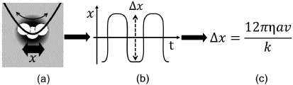
Figure 3. Calculation of the merit factor. (a) Viscous drag force imparted on the trapped particle causes it to oscillate (thin arrow) in the harmonic potential well of the trap. The drag force was imparted by the dispersion water through motion of the sample stage (thick arrow). (b) The amplitude of this oscillation (dashed arrow) is directly proportional to the spring constant k via Stokes' law (c).
Download figure:
Standard image High-resolution imageTo test the ability of the adaptive optics to correct for the aberrations at depth a particle was initially trapped close to the cover slip surface and then moved deep into the sample with the z-translation stage. Optimizations were performed by moving the microscope objective from depths of 50 to 175 μm in 25 μm steps which resulted in actual optical trapping depths of 44, 66, 88, 109, 131 and 153 μm. This discrepancy is due to the glass/water interface and moving the objective over a distance Δlens with respect to the interface causes a shift in the position of the focus of Δpeak [10]. According to Wiersma et al, this shift can be predicted using a paraxial geometric approximation to be △lens/△peak ≈ noil/nwater = 0.875 [27]. All trapping depths given in this paper were calculated by multiplying the distance the objective has moved according to the stage display with this factor.
To assess the success of the RSA and merit factor, we measured the lateral trap stiffness with trap depth by observing the Brownian motion of the trapped particle and using the theory of equipartition to calculate k, this was performed with and without aberration correction. The equipartition of energy dictates that the thermal energy per degree of freedom must equal the potential energy of the trapped particle,  where KB is the Boltzmann constant and T is temperature (taken to be 298° K). Therefore, the spring constant k of the trap can be calculated by measuring the variance 〈x2〉 of the residual motion of the trapped particle using the centre of mass particle tracking algorithm. We increased the frame rate of the camera to 1.5 kHz (for an exposure of 650 μs) by selecting a small region of interest around the trapped bead, roughly 40 × 40 pixels in size, allowing us to measure 20 000 data points over a time period of roughly a minute and accurately quantify x2. To avoid a strong bias towards the geometrical centre of the region of interest a threshold was set on the images to create a black background with the image of the particle in the centre [28]. The DMM shapes saved in the look up table were used to acquire scatter plots of the Brownian motion of a trapped particle with depth, starting at 22 μm and in roughly 4 μm intervals, until the particle was ultimately lost from the trap. This data allowed the calculation of the trap stiffness in x- and y-direction for each optimized DMM shape over a range of trap depths. Each scatter plot data set was binned, using the same parameters, and converted into a matrix for further analysis.
We analysed the aberration correction applied with each DMM shape in the look up table by imaging the DMM surface onto the sensor array of a Shack–Hartmann wavefront sensor (Thorlabs WFS150C) using a 4f system. The wavefront sensor expressed modal content of the DMM shape in terms of Zernike modes. Zernike modes are a complete set of orthonormal polynomials over the unit circle and a common way of describing wavefronts and optical aberrations in adaptive optics.
4. Results
Three representative xy scatter plots are shown in figure 4. The first row shows the scatter plot of the Brownian motion of a particle which was trapped with the flat DMM shape at depths of 44 μm, 88 μm and 131 μm respectively while the second row shows the scatter plot when the particle was trapped with a DMM shape that had been optimized for each respective depth. From the reduced spread of the plots and the increased peak value it can be seen that each optimization successfully increased the stiffness of the trap. This is quantitatively confirmed by the insets stating the trap stiffness in x- and y-directions in pN μm−1. It is also noticeable that the optimization succeeded in making the trap strength more uniform in both lateral directions. Before aberration correction the scatter plot took on an elongated, elliptical shape which is attributed to different trapping strengths in x- and y-directions. This asymmetry in the xy plane is due to the linear polarization of the laser beam along with circularly asymmetric aberrations like coma and astigmatism. After aberration correction the scatter plot shows a more circular distribution. Trapping force uniformity has been quantified by calculating the eccentricity of the optical trap given by  for kx ≥ ky. The third row in figure 4 shows the same data plotted at fixed x position and the Gaussian fit to the data. In the un-optimized case the Gaussian bell broadens and flattens out with increasing depth while the optimization is able to keep the width and amplitude of the Gaussian curve on an almost constant level. The insets give the width of the Gaussian fit in nm for the uncorrected (wu) and aberration corrected case (wc). A full list of spring constants before and after aberration corrections for the x- and y-directions and the eccentricity with increasing depth can be seen in table 1.
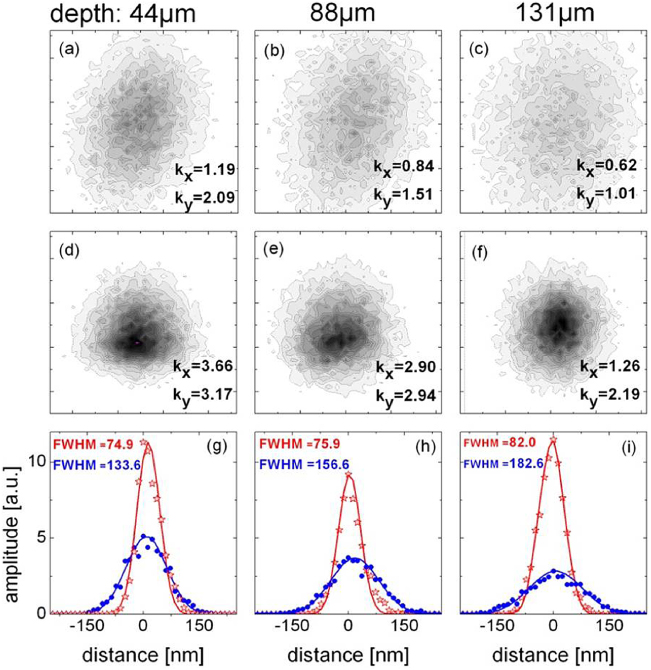
Figure 4. Contour plots of 20 000 scatter points before (first row) and after aberration correction (second row) (linear scale) and Gaussian curve fitting to the scatter plots at x = xmax before aberration correction (blue circles) and after aberration correction (red stars) at a depth of 44 μm (a,d,g), 88 μm (b,e,h) and 131 μm (c,f,i). Size of scatter box: 250 nm × 250 nm. Insets: spring constants in x- and y-directions in pN μm−1 and width of the Gaussian fitting in the uncorrected (wu) and aberration corrected case (wc) in nm.
Download figure:
Standard image High-resolution imageTable 1. Spring constants kx and ky as measured before and after aberration correction and their derived eccentricities through depth.
| Depth (μm) | Value | Before | After | Improvement ratio |
|---|---|---|---|---|
| 44 | kx (pN μm−1) | 1.26 | 3.66 | 2.90 |
| ky (pN μm−1) | 2.19 | 3.17 | 1.45 | |
 |
0.82 | 0.50 | 1.64 | |
| 66 | kx (pN μm−1) | 1.05 | 3.17 | 3.02 |
| ky (pN μm−1) | 1.84 | 2.87 | 1.56 | |
|
0.82 | 0.42 | 1.95 | |
| 88 | kx (pN μm−1) | 0.88 | 2.90 | 3.30 |
| ky (pN μm−1) | 1.59 | 2.94 | 1.85 | |
|
0.83 | 0.16 | 5.19 | |
| 109 | kx (pN μm−1) | 0.81 | 2.28 | 2.81 |
| ky (pN μm−1) | 1.40 | 2.46 | 1.76 | |
|
0.81 | 0.38 | 2.13 | |
| 131 | kx (pN μm−1) | 0.68 | 2.97 | 4.37 |
| ky (pN μm−1) | 1.13 | 3.74 | 3.31 | |
|
0.80 | 0.61 | 1.31 |
The evolution of spring constants with increasing depth is depicted in more detail in figure 5. It is clearly noticeable how the stiffness of the trap deteriorates with trap depth when no aberration correction is applied. While k is 1.721 and 2.715 pN μm−1 in the x- and y-direction respectively at 22 μm, this value decreases by 64% to 0.618 and 1.011 pN μm−1 in the x- and y-direction respectively at a depth of 131 μm. At a depth of 136 μm the particle can no longer be trapped. The spring constants for three optimizations, performed at depths of 44 μm, 88 μm and 131 μm respectively, are also shown. The arrows mark the specific depth at which the respective optimization was run, whereas the other data points indicate how this optimization performed at a depth for which it had not been specifically optimized for. Every optimization substantially increased the lateral stiffness of the trap. However, individual optimizations show quite different behaviour in terms of the range over which they might be usefully applied. We arbitrarily define the depth interval over which we call a mirror shape applicable as the range within which the spring constant remains within 5% of its optimized value. While the DMM shapes that were optimized at depths of 44 μm and 131 μm have similar ranges of applicability and remain within 5% of their respective optimized spring constant value within a range of 35 μm and 33 μm respectively, the shape obtained at 88 μm shows an increased range of applicability of 68 μm. In our experiments the maximum trapping depth has been increased from 136 μm for the at DMM shape to 166 μm for the DMM shape optimized at 131 μm.

Figure 5. Evolution of spring constants with depth using different DMM shapes. The blue squares relates to a flat DMM shape, the purple circles a DMM shape optimized at a depth of 44 μm, the green squares a shape optimized at a depth of 88 μm and the empty circles a shape optimized at 131 μm. The arrows mark the specific depth at which the respective optimization was run, whereas the other data points indicate how this optimization performed at a depth for which it had not been optimized. The lines have been displayed as a guide to the eye.
Download figure:
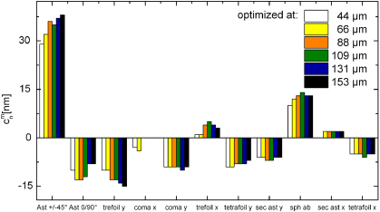
Standard image High-resolution imageFinally, figure 6 compares the modal content of each DMM shape in terms of Zernike coefficients. The dominant higher order aberrations in our setup were astigmatism and spherical aberration along with trefoil.
Figure 6. Modal content of the DMM shapes in terms of higher order Zernike aberrations.
Download figure:
Standard image High-resolution image
5. Discussion
The predominant aberrations found in our setup occur commonly in imaging. In this work, coma in y direction and secondary astigmatism appear to be constant over the entire depth range which implies they are system induced, originating from the optics in the system pre-sample. Coma is most pronounced when a microscope is out of alignment and components are hit by off-axis beams. Astigmatic aberrations are often found in multielement systems similar to that employed here and are likely to be responsible to the high level of asymmetry found in the uncorrected system as shown in figure 4. This is due to the meridional plane being usually coherent throughout the setup whereas the equatorial plane usually changes in the incident angle with each optical element. Other aberrations like astigmatism along ±45° and spherical aberration show a distinct trend with depth. This indicates that their origin is due to the system and sample and specifically due to trapping at depth and the refractive index mismatch between the oil/glass–water interface. In order to accurately correct for spherical aberration it would be necessary to observe the particle motion along the optical axis or the z-axis. In principle it would be possible to use Zernike modes as the basis set for the algorithm, the success of this approach would depend on how accurately the Zernike modes could be reconstructed using the mirror surface, in practice this is non-trivial.
Most aberrations have two counterparts corresponding to the two orthogonal, independent directions, for example coma along x and y or astigmatism at ±45° and 0°/90°. The coordinate system with which the aberrations are decomposed and defined is given by orientation of the wavefront sensor with regards to the optical system. If the coordinate system of the aberrations were to coincide exactly with the direction of the applied drag force then any optimization would potentially only apply to one type of coma and not the other for example. For the majority of cases, where the direction of the applied viscous drag force does not align exactly with one of the axis of the wavefront sensor coordinate system then it is possible to correct for all aberrations, this is true of our system and can be seen clearly in figure 6 where we correct for both forms of coma and astigmatism. The 'risk' of running exactly along the axis of an aberration increases with increasing radial order as the patterns becomes more intricate. However, these higher order aberrations will have less effect on the strength of the trap and are less likely to play a part in the aberration correction.
It is interesting to compare our measured k values with those published by others under similar experimental conditions. Polin et al reported the trapping of a silica particle (1.53 μm diameter) with a lateral spring constant of k = 0.71 pN μm−1 and an incident power of 5 mW at an unspecified depth [29]. Ghislain et al trapped a 1 μm diameter particle at a distance of 8 μm under the coverslip with an incident power of 60 mW and measured a lateral spring constant of kr,exp = 60 pN μm−1 [8]. Considering the reduced power and greater trapping depth in our experiment these results are in good agreement. Also a decrease of the lateral trap stiffness by 12% was reported by the same group when a polystyrene particle of 1 μm diameter is trapped close to the cover slip surface and then 21 μm deeper into the sample. This drop in lateral trap stiffness is in agreement with the decrease measured in our experiments, although our experiment goes on to measure k up to a trap depth of 136 μm.
In terms of level of correction achieved our approach, resulting in an average lateral improvement factor of 2.63, compares well with other methods and is generally higher. In many cases a direct comparison is hard since an SLM is used or the bead size or range of trap depths etc is different. It is clear from Theofanidou et al, who optimize on the two-photon fluorescence from a strained bead, that optimizing on a merit factor that it directly proportional to the trap strength is advantageous [21]. In addition, by allowing the DMM to correct for all aberrations, not just spherical, we see a larger improvement factor than Ota et al who reported factors of 1.35 and 1.83 when they used a DMM to correct for spherical aberration [22].
Each optimization took roughly 60 iterations, the manufacturer's quote the rise time of a single actuator to be less than 5 ms, therefore, in theory, an optimization should take less than a second. In practice the optimization algorithm used here took a lot longer, typically 30 min up to an hour, this was due to the in-house software used which displayed several diagnostics of the system continuously and allowed for a long pause between optimizations to ensure the bead was still trapped and that the drag force had reached an new equilibrium. In future experiments it is anticipated that this time could be reduce to less than 10 min, ∼6 iterations a minute.
The search space of mirror shapes is, in theory, of infinite dimensions. However, as the shape of the DMM is controlled via 52 actuators, the search space of possible mirror shapes is in practice reduced to 52 dimensions. Within this search space there is no certainty that a unique solution exists to a given problem as several different mirror shapes could well lead to the same improvement in merit factor. Inversely, each optimization could end in a different mirror shape if it were to be repeated under the exact same conditions and not left to run indefinitely, giving a possible explanation for the different ranges of applicability of mirror shapes in this work.
6. Conclusion
We have demonstrated the use of a DMM to increase the lateral trapping force of an optical trap. The optimum shape of the DMM was determined with a random search algorithm using lateral particle displacement from equilibrium due to a viscous drag force as a merit factor. This displacement from equilibrium is directly proportional to the stiffness of the optical trap, the property of the trap we sought to improve. A study of trap stiffness with and without aberration correction at varying trap depths reveals that the stiffness of the trap can be improved throughout the trapping range of a conventional optical trap and beyond. The average improvement factor achieved was 2.63 in x and y. At a depth of 131 μm the trap stiffness was improved by a factor of 4.37 and 3.31 for the x- and y-axis respectively. The maximum trapping depth was increased from 136 to 166 μm. Furthermore, the same mirror shape obtained from an optimization at one depth leads to an improvement of trap stiffness throughout a wide range of trap depths. The optimization routine also has the beneficial effect of making the trapping forces in the lateral directions more uniform and hence reducing the eccentricity of the trap. A benefit of this approach is that is relies on no prior knowledge of the aberrations present and therefore running a single optimization routine at a given depth will correct for both the system and the sample induced aberrations. In future the routine could potentially be sped up by using an 'intelligent starting point' to the optimization, for example, starting with a DMM shape determined at a different trap depth. This technique will prove useful in applications of optical traps as force transducers where a constant and uniform lateral trapping force with increasing depth is paramount or when the viability of the trapped particles/cells is of concern.
Acknowledgments
The authors would like to thank Richard Bowman (University of Glasgow) and Loyd J McKnight (University of Strathclyde) for their help. AJW acknowledges funding from EPSRC and the Royal Academy of Engineering and MCM from the Scottish University Physics Alliance (SUPA) prize studentship. Preliminary work was supported under the EU ACCORD scheme in collaboration with Imagine Optic.