
Abstract
Thin layer membranes with controllable features and material arrangements are often used as target materials for laser driven particle accelerators. Reduced cost, large scale fabrication of such membranes with high reproducibility, and good stability are central for the efficient production of proton beams. These characteristics are of growing importance in the context of advanced laser light sources where increased repetition rates boost the need for consumable targets with design and properties adjusted to study the different phenomena arising in ultra-intense laser-plasma interaction. We present the fabrication of sub-micrometric thin-layer gold or aluminum membranes in a silicon wafer frame by using nano/micro-electro-mechanical-system (N/MEMS) processing which are suitable for rapid patterning and machining of many samples at the same time and allowing for high-throughput production of targets for laser-driven acceleration. Obtained targets were tested for laser-proton acceleration through the Target Normal Sheath Acceleration mechanism (TNSA) in a series of experiments carried out on a purpose-made table-top Ti:Sa running at 3 TW peak power and 10 Hz diode pump rate with a contrast over ASE of 108.
Export citation and abstract BibTeX RIS

Original content from this work may be used under the terms of the Creative Commons Attribution 3.0 licence. Any further distribution of this work must maintain attribution to the author(s) and the title of the work, journal citation and DOI.
Laser-driven plasma ion acceleration has attracted notable attention due to its ability of providing ion beams with energies up to tens of MeV over very short acceleration distances, typically a few micrometers [1]. This could pave the route to high quality energetic ion beams for a number of scientific, medical and technological applications ranging from fast ignition [2], charged particle radiography[3], ion therapy [4, 5], and radioisotope production [6]. The field is further boosted by the increasing availability of extreme light infrastructures owning the promise to allow for ultra-high power laser experiments at unprecedented repetition rates between Hz and kHz in the near future [7].
The most investigated laser acceleration mechanism to date is the so-called Target Normal Sheath Acceleration (TNSA), which is the leading mechanism at currently accessible laser intensities of 1018−1021 W cm−2 [8, 9]. In this scenario, ions are accelerated from the rear target surface by the intense electric field built up by relativistic electrons originating from the laser beam incidence on the front surface of the target, typically a thin solid foil of 0.1 ÷ 10 μm thickness [10]. In order to use TNSA for practical applications it is necessary to improve the acceleration performance in terms of maximum ion energies, beam current and spectral shape. To this purpose, several groups have recently focused on the development of smart targets beyond the thin foil concept to increase the energy transfer from the laser pulse to the accelerated ions. For example, nano and micro structured surfaces have proven advantageous to increase maximum proton energies [11] while higher ion yields with a narrower energy spread have been observed from metallic targets carrying micro-dots with a high content of hydrogen [12].
However, few authors have focused until now on the development and validation of strategies for a cost effective and high-throughput production of solid targets for laser driven particle accelerators. This is the key to meet both the technological challenges for the production of proton beams, and to fully exploit the oncoming possibilities of PW pulses available at high-repetition rates. Current N/MEMS processing, including either top-down and bottom-up fabrication routes, are very suitable for this purpose as discussed in [13]. MEMS have been previously applied in this context to fabricate silicon membranes of about 17 μm doped with hydrogen which were shown able to produce high-current and multi-MeV proton beams [14]. Here, we focus on the fabrication and characterization of sub-micrometric metallic membranes according to MEMS processing.
Micro-and nanometer thick aluminum or gold membranes embedded in a silicon frame were obtained by processing standard 4 inch (100 mm) silicon wafers (525 μm thickness) as schematized in figure 1, involving pattern transfer and sacrificial layers etching.

Figure 1. Principal steps of the fabrication process. (Drawing not to scale).
Download figure:
Standard image High-resolution imageFirst, a thermal SiO2 layer (1019 ± 3) Å thick is grown on both wafer sides followed by a low stress Si3N4 layer with a thickness of (1810 ± 24) Å deposited on the front side through low pressure chemical vapor deposition (LPCVD) and then exposed to UV light through the etch mask. After development of exposed regions, unexposed layers were dry etched in a CHF3 atmosphere. Thereafter, back wafer sides were metalized either by a sputtered aluminum layer with thicknesses ranging between 0.25 μm and 1 μm, or by three evaporated layers of 20 nm of Ni, 30 nm of Ti, and 70–100 nm of Au. Once back metalized, 2 μm of the positive photosensitive resist AZ 6512 were spin-coated on the back side and then exposed to UV light through the mask. After resist development, exposed regions are etched in a chemical bath leaving in this way the desired aluminum, or gold, pattern confined within the area corresponding to that of the window to be opened on the front side. The latter is accomplished by using anisotropic etching of silicon in a hot bath (80 °C) of 30 wt% KOH solution followed by rinsing with deionized water for 5 min. Silicon micromachining is spontaneously stopped by the underlying buried oxide. KOH etching of silicon is based on the different etching rates of the hydroxide ions contained in the alkaline solution on silicon crystal planes, which is fastest for (100) and (110) planes and lowest for (111) planes. This, results in the typical 'V' shaped 3D structures like the truncated pyramids visible in figure 1. Then the SiO2 layer is etched away in a 1 wt% HF bath. In addition, we also used targets with membranes supported on the thin silicon oxide layer (i.e., omitting this etching step) and compared results from both target configurations.
The targets are arranged in arrays covering major parts of the wafer surface. Each target cell (1 cm2) contains up to 16 thin layer membranes with a surface area of (1000 μm)2 embedded in a silicon frame to achieve high-throughput production of thin-layer membranes with reproducible properties. Fabricated membranes are found in a state of compressive stress and show the typical buckled folding with worm-like shapes which can be appreciated in figure 2(a). The residual mechanical stress exhibited by CMOS thin film materials is deeply related to the process flow and the deposition techniques used [15]. This is usually compensated either by depositing a passivating layer of silicon nitride characterized by tensile stress opposite to SiO2 [16], or by applying thermal cycles [17]. In our case, a rapid annealing of membranes above 400 °C is sufficient to convert compressive stress into tensile one resulting in flat membranes, as those represented in figure 2(b), which are beneficial for a precise laser alignment and focusing on the target, although more fragile. Atomic force microscopy (AFM) characterization results are shown in figures 2(c)–(d) and represent 3D view reconstructions of the surface analysis. According to these, the surface roughness increases with the oxide layers thickness, in agreement with former results [18].
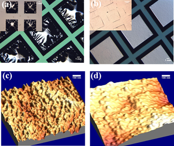
Figure 2. (a) Optical microscope picture of fabricated membranes in compressive stress and (b) membranes in tensile stress (in the insets the same on the respective back wafer sides). (c) and (d) 3D renderings of AFM pictures showing surface roughness for 1 μm Al membranes supported by 100 nm and 300 nm of SiO2, respectively.
Download figure:
Standard image High-resolution imageProton acceleration experiments have been performed on a purpose-built Ti:Sa laser operating at a wavelength of 0.8 μm and based on Chirped Pulsed Amplification (CPA). It can deliver pulses of 265 mJ (165 mJ on target) with a duration of 55 fs (FWHM) up to a repetition rate of 10 Hz and has recently been commissioned in systematic tests on flat foil targets obtaining maximum proton energies around 1.7 MeV [19]. The amplified spontaneous emission (ASE) level was around 10−8 of the main pulse. The pulse is focused on the target by a f/3 off-axis parabola with a focal spot size of about 5 × 11 μm2 (FWHM) measured with a camera, and which results in an irradiance on target of I ≈ 4 × 10¹⁸ W cm−2. Target positioning is controlled through a He:Ne laser coupled along the same optical path of the Ti:Sa beam.
Inside the interaction chamber, the target holder is mounted on a motorized system providing x, y, z movement with a precision of 2.5 μm. The holder can load up to 16 target cells resulting in 256 spots available in one vacuum cycle (figure 3(a)). It is suitable for exploring systematically the effects of various target parameters in one experiment.

Figure 3. (a) Holder with mounted target cells. (b) The focus is adjusted in position 1 and the following shots (2–6) are performed within ±100 μm from the focus.
Download figure:
Standard image High-resolution imageLaser pulses are focused on membranes at an incidence angle of 30° to prevent detector damage and to avoid back reflection. The longitudinal focus position is adjusted for only one membrane of each cell by means of a back reflection interference pattern which is formed on the target surface provided a roughness of the order of the laser wavelength [20]. Then it is maintained throughout membranes belonging to the same cell. Some laser shots have been performed at longitudinal distances between −100 μm and 100 μm (figure 3(b)) from the optimum focus to study the influence of the alignment precision on the measured proton energies.
The spectral characterization of accelerated protons was achieved by two different particle detectors as detailed in [19]. A time-of-flight (TOF) detector based on a fast plastic scintillator coupled to a photomultiplier (PMT) was mounted at a distance of 227 cm behind the laser target. The PMT anode pulses were recorded on a fast digital oscilloscope. In addition, for some laser shots a passive material (CR-39 plates) which is highly selective for the detection of protons and ions was placed 100 cm behind the target. After 4 h etching at 90 °C in a 6.25 M NaOH bath, spectral information can be obtained from a unique relation between proton energy and measured track diameters. To extend the energy range aluminum absorber foils (up to 43 μm thickness) were used to cover the CR-39 plates and the corresponding energy loss was corrected with SIMNRA [21].
All experiments were carried out in a regime of low repetition rate with laser pulses of 265 mJ and 55 fs duration. Clear proton tracks on CR-39 detectors have been observed for all tested membrane thicknesses and material compositions, an example is shown in figures 4(a) and (b). Typical proton energy spectra obtained from TOF data are shown in figure 4 (c).

Figure 4. (a) and (b) CR-39 plates covered with 18 μm and 35 μm Al absorbers, respectively, used for showing proton tracks from 0.65 μm Al membranes supported on 400 nm of SiO2. (c) Proton spectra obtained by the TOF detector at five longitudinal positions with respect to the laser focus.
Download figure:
Standard image High-resolution imageIn figure 5 the maximum proton energies around the focus position are compared for different membranes. Maximum proton energies have been obtained from TOF data and the uncertainty, where depicted, has been determined by averaging over at least three shots. Otherwise data points are intended to be single-shot measurements results. For all thicknesses, the highest energies have been observed close to the position of the smallest laser focus (0) except in the case of the 0.5 μm membrane where the maximum is slightly shifted to the left, in agreement with the precision of the initial positioning (±25 μm). The maximum proton energy suffers only slight variations (less than 10%) in intervals of ±50 μm around the focus position.
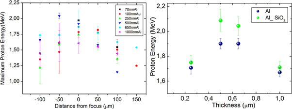
Figure 5. (a) Maximum proton energy around focus position, as obtained with the TOF detector, for membranes with different thicknesses and material composition. (b) Comparison between maximum proton energy for aluminum membranes supported or not by SiO2.
Download figure:
Standard image High-resolution imageIn the range of target thicknesses investigated here the maximum proton energies are quite similar. Thinner gold membranes have almost the same performance as thicker aluminum ones (see figure 5(a)). This is in agreement with previous results from the same setup, but using flat foil targets [19], and has also been observed in former experiments with similar laser contrast [22]. A direct comparison of aluminum membranes supported by a nanometric oxide layer and free-standing ones, obtained after SiO2 etching, may indicate slightly higher proton energy with SiO2, as shown in figure 5(b). These results could be explained in terms of the increased content of hydrogen in the bulk of these targets which thus provide a uniform amount of protons throughout the target, as observed in [23]. They should be confirmed in more detailed experiments and possibly at higher laser contrast as they are especially interesting from the fabrication point of view, because etching of SiO2 is a quite critical step requiring very short dipping times (≈1 s) and the use of hydrofluoric acid.
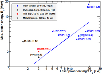
Finally, in figure 6 we compare our results with those of published experiments. We focus our attention on a temporal interval similar to ours (30–65 fs) and target thicknesses below 1 μm. Data obtained with our setup are coherent with previous results [22, 23, 24–27] considering the moderate laser power, and with the scaling typical of the TNSA mechanism for particle acceleration [28]. Previous measurements with flat membranes produced with MEMS techniques are rare. One result by Picciotto et al [14] is included in figure 6 for completeness although the experimental conditions using a 500 J, 300 ps laser were very different to the others.
Figure 6. Comparison between maximum proton energy versus laser energy on target from published experiments (blue), with our setup (black solid triangle), and from this experiment (red). A previous result from MEMS targets by Picciotto et al [14] is included (hollow triangle). Materials and thickness (μm) are indicated in the labels. The line is the result of calculations assuming the model of Zeil et al [28].
Download figure:
Standard image High-resolution image
We have presented the large-scale fabrication of conductive, submicrometric membranes used as targets for ultra-intense laser-plasma interaction by applying standard MEMS manufacturing methods allowing for high throughput production of membranes, which were shown advantageous for laser-driven proton acceleration with respect to plain foils typically employed as targets for ultra-intense laser experiments. MEMS based processing makes it possible to tune the membrane properties, such as thickness and material composition, with great flexibility, and to adapt them to different experimental needs. Our aim is to reduce the lateral size of our structures at least by a factor 5 to increase significantly the number of individual targets. This would be very advantageous for the development of laser-plasma applications relying on high repetition rates.
Acknowledgments
The authors highly appreciate the collaboration of Radosys (Budapest) which provided CR-39 detector material, etching bath, and readout equipment. This project has been financed by the Spanish Ministry for Economy and Competitiveness within the Retos-Colaboración 2015 initiative, ref. RTC-2015-3278-1. P Mur has received a grant of the Garantía Juvenil 2015 program. This work has made use of the Spanish ICTS Network MICRONANOFABS partially supported by MEINCOM.