
Abstract
Embedded actuator and sensor technology provides accurate structural health monitoring and proper structural response of a structure in any harsh servicing situation. This paper describes the fabrication of a smart composite by embedding shape memory alloy (SMA) wires and fibre Bragg grating (FBG) sensors into a glass fabric reinforced polymeric composite. Mechanical performances of the composite under martensitic and austenitic stages of the SMA wires were studied, and its natural frequencies were also measured accordingly. The result shows that the shift of the natural frequency arises from temperature change, thus changing the mechanical properties of the SMA wires. The changes of strain, stress, curvature, and damping ratio were predicted from an asymmetrical lamination model. It was found that this model demonstrates certain attractive effects, including mechanical properties, the change of shape, and the natural frequency upon activation of the SMA wires.
Export citation and abstract BibTeX RIS
1. Introduction
The potential of glass fibre reinforced plastics (GFRPs) in the global market is enormous, and this global market will grow to a total of US $29.4 billion in 2013 [1]. GFRPs have already been employed widely in aerospace, automotive engineering, railway, and wind energy industries for many years. However, their main disadvantage is their complex failure mechanisms. Smart materials have attracted growing interest as they responds to environmental stimuli in particular conditions, and this has lead to many potential applications. Embedded sensor and actuator technology is a promising solution to provide active control on composite structures. Therefore, the market tends to focus on the development of smart composites whose properties are altered appropriately in response to environmental fluctuations, rather than on conventional GFRPs. These smart composites are defined as an integrated structure consisting of actuating and sensing devices to form a smart system similar to a human body [2–4].
Fibre reinforced composites with embedded shape memory materials have been extensively focused on because of their superior potential for the applications of vibrational and structural controls [5]. The advantages of shape memory alloy (SMA) in the field of actuating systems include (1) high reversible strain, (2) high damping capacity, (3) large reversible change of mechanical and physical characteristics, and (4) high recovery stresses [6]. SMA composites demonstrate their extraordinary performance in adjusting their shape, vibration, acoustic transmission, and impact resistance through a centralized control system; for instance, vibration control can be achieved by controlling the stiffness of SMA wires with heat, and thus the whole composite structure [7].
A fibre Bragg grating (FBG) sensor is an optical fibre sensing technology that has drawn enormous attention for over 20 years [8–11]. The advantages of FBG sensors include the following: (1) they are light in weight, (2) they are small in size, without degradation of structural integrity, (3) they are insensitive to electromagnetic interference, (4) they have a high degree of multiplexability, and (5) they have the ability to be used in environmentally unfavourable conditions [12]. Embedding an FBG sensor into a composite helps to monitor the curing temperature of its structure during the manufacturing process; the sensor can subsequently be used for lifetime performance monitoring [13].
A multi-layer asymmetric composite structure starts to be bent when subjected to a temperature change. An asymmetric structure is formed by orientating fabric layers in different directions or constructing the structure using distinct materials with different mechanical properties and coefficients of thermal expansion (CTEs). The asymmetrical lamination of a composite can result in the combined effect of bending moment and laminate extension. Another phenomenon is the formation of curvature resulting from an action to bending of an asymmetrical laminate under temperature change [14]. An undesirable formation of the curvature is unfavourable to a composite structure if it is applied to real-life engineering applications. Korakianitis et al [15] have found that the change of curvature of a composite blade affects the aerodynamic profile of the blade seriously, which in turn induces some problems of vibration and stalling of the airflow. Besides, they have also found that an appropriate blade curvature design results in maximizing the aerodynamic performance with a prevention of flow separation [15].
However, existing studies of SMA reinforced composites have revealed the lack of basic understanding of the effect on their temperature change, especially the issues concerning the generation of distinct thermal expansions because of their hybrid material properties. Therefore, the mechanical and acoustic properties of these composites have to be well understood before implementing them in real-life engineering applications. In this paper, the mechanical and dynamic properties of an asymmetric SMA reinforced composite subjected to a temperature change have been investigated through experimental and theoretical approaches.
2. Experimental study
2.1. Materials
Ni–Ti alloy SMA wires with a diameter of 0.2 mm were used in the current study. Polymeric matrix GY251 epoxy resin mixed with GY956 hardener was supplied by Shing Hing chemical Co., Ltd. The ratio of the epoxy resin to the hardener was 5:1. The plain weave glass fabrics (style AF218) that were used to make a composite were supplied by Colan, Australia.
The FBG sensors used in this study were written in polyimide-coated, standard monomode optical fibres. The gratings were fabricated and centred in λB = 1540, 1536, or 1530 nm, with a gauge length of 8 mm.
2.2. Sample manufacturing
The optical fibres and SMA wires were cleaned by ethanol applied to a lint-free wipe to remove contaminants including dust particles, human hand oils, and so on, in order to enhance the adhesion of the optical fibre and SMA wires to the surrounding epoxy matrix.
Composite samples were made by a hand lay-up process, which was followed by vacuum bagging and mounting inside a frame. The frame was used for prestraining and aligning the SMA wires and optical fibres in the right direction. In total, eight plies of glass fabrics were used. The length, width, and thickness of the composite beam for the calibration and tensile tests were 200 mm × 30 mm × 1.94 mm, respectively. Two types of lamination symmetric and asymmetric composite were prepared. Symmetrical composite beams were fabricated for temperature and strain calibration tests. The SMA wires and the optical fibre were embedded in the same plane and at the mid-thickness of the composite beam, as shown in figure 1(a). The asymmetric composite beam was fabricated as indicated in figure 1(b).
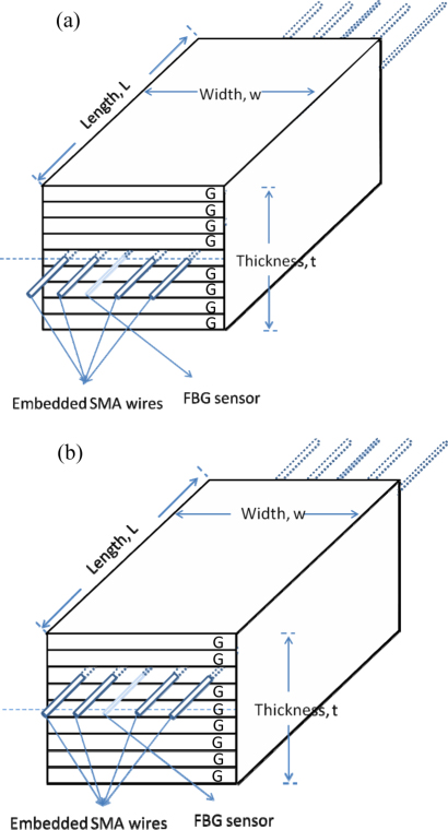
Figure 1. Model of the composite for (a) the strain and temperature calibrations and (b) the experimental and theoretical analyses. (G represents a layer of glass fabric.)
Download figure:
Standard image High-resolution imageFor the composite beam fabricated asymmetrically, six layers of glass fabric were underneath the SMA wires, and the optical fibre and two layers were placed above. The distance between the SMA wires and the optical fibre with a prewritten FBG grating (FBG sensor) was 5 mm. In total, five SMA wires were embedded in parallel into the composite.
2.3. FBG detection system
An array of at least two FBG sensors was used in each composite sample. One of the FBGs was embedded inside the composite beam as a strain sensor while another was attached to the composite beam's surface as a mechanical-strain-free sensor to compensate for the thermal strain effect. A pigtail of the array was spliced into a patchcord and connected to an interrogator. A PC with the LabView program was connected to the interrogator for data acquisition. Interrogator models sm125 and sm130, from Micron Optic Inc., were used in the experiment for static and dynamic measurements, respectively. The sampling frequency and measurement resolution of the static machine were 1 Hz and 1 pm, and the corresponding values for the dynamic machine were 2000 Hz and 5 pm.
2.4. Symmetrical composites
2.4.1. Temperature and strain calibration of the FBG sensors.
An FBG sensor can be made using different fabrication techniques, and consequently different sensing properties are obtained. Therefore, the strain and temperature sensitivity coefficients of the FBG sensor should be determined experimentally by conducting the calibration test prior to any property test of the composite beams. In this study, the calibration of strain and wavelength shift of the sensor was determined by performing a simple uniaxial tensile test of the sample, as shown in figure 1, at room temperature. The change of strain was measured with a surface-mounted strain gauge. The wavelength shift induced by the applied strain ε at constant temperature is given by the following equation [16]:

where Pe is the photoelastic coefficient of the fibre and Kε is the strain sensitivity. The linear correlations between the change of ΔλB/λB with the change of applied load and the change of ΔλB/λB with the change of strain are shown in figures 2(a) and (b). Kε is obtained as the slope of the graph of ΔλB/λB versus the strain variation (με), which is equal to 7.5 × 10⁻⁷ ((pm/pm)/με). The result indicates that every 1.16 pm shift of the Bragg wavelength of the FBG sensor corresponds to 1 με in the case of 1541 nm wavelength.
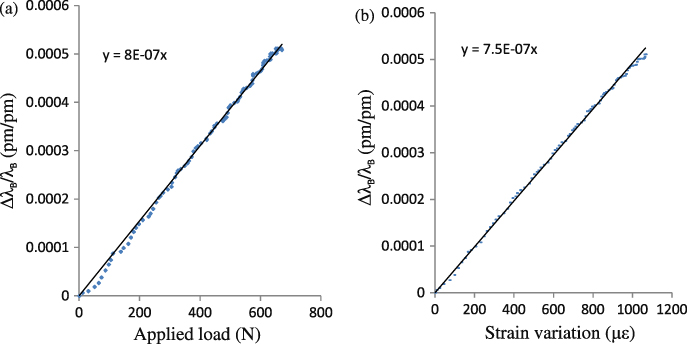
Figure 2. ΔλB/λB versus (a) the applied load and (b) the strain variation in the strain calibration test at room temperature.
Download figure:
Standard image High-resolution imageTo calibrate the thermal-induced strain of the FBG sensor, the composite beam was heated up by the embedded SMA wires via electrical resistance heat, that is, by applying the current to the wires and using their electrical resistance properties in order to generate heat themselves. Since the SMA wires were embedded into the composite beam which is relatively thin, the surface temperature of the composite beam at the location where the wires were embedded should be very close to the temperature of the SMA wires. The simultaneous wavelengths of the strain-free FBG were recorded from room temperature to 35 ° C. According to the temperature change measured by thermocouples, the corresponding wavelength shift is given by [16]

where the temperature sensitivity coefficient ST = α + ξ, in which α is the thermal expansion coefficient and ξ is the thermo-optic coefficient. The linear correlation between the change of ΔλB/λB and the temperature is shown in figure 3. ST was obtained as the slope of the graph of ΔλB/λB versus the change of temperature. From figure 3, it can be see that ST is 6.2 × 10⁻⁶ ((pm/pm)/°C−1). This result demonstrates that every 9.55 pm shift of the Bragg wavelength of the FBG sensor corresponds to 1 ° C in the case of 1541 nm wavelength.
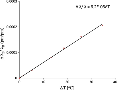
Figure 3. Temperature calibration for the FBG sensor.
Download figure:
Standard image High-resolution image2.5. Unsymmetrical composites
2.5.1. Mechanical properties.
A tensile test was conducted to obtain the Young's modulus of the composite beam, as shown in figure 1(b). The composite beams were mounted onto the MTS testing machine (Alliance RT/50) with tailor-made supporting fixtures for the test. The crosshead speed of the test was 1.5 mm min−1. The phase transformation temperatures of the SMA wires were measured by using a differential scanning calorimeter (DSC), and the results are listed in table 1. A DC supplier was used to supply electrical current into the wires to generate electrical resistance heat to a specified temperature. The properties of the composite beams at the SMA's transformation temperatures, namely the martensite finish temperature (Mf) and the austenite finish temperature (Af), are shown in table 1.
Table 1. Material and mechanical properties of the SMA and composite materials.
| Description | |
|---|---|
| SMA | |
| Coefficient of thermal expansion (CTE) | |
| Martensite (°C−1) | 6.6 × 10⁻⁶ |
| Austenite (°C−1) | 11 × 10−6 |
| Transformation temperatures (° C) | |
| Martensite finish (° C) | 20 |
| Martensite start (° C) | 35 |
| Austenite finish (° C) | 60 |
| Austenite start (° C) | 45 |
| Glass fibre epoxy composite | |
| Young's modulus (GPa) | 25 |
| CTE of glass fibre (m3 °C−1) | 4 × 10⁻⁶ |
| CTE of epoxy (m3 °C−1) | 55 × 10−6 |
| SMA composite | |
| Young's modulus at RT (MPa) | 2900 |
| Young's modulus when T > Af (MPa) | 2470 |
| Density (kg m−3) | 2500 |
Figure 4 shows the stress–strain curve obtained from the tensile test and conducted at (a) room temperature and (b) 50 ° C. Notwithstanding that the Young's modulus of the composite beam at T < Mf is higher than that measured at T > Af, the strength of the composite beam at T < Mf is lower than that at temperature above Af. This result confirms that the composite beam is more ductile when the SMA wire is in its martensitic state as compared to that in the full austenitic phase.
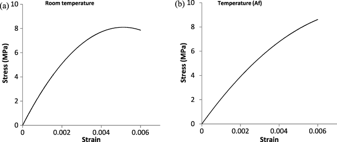
Figure 4. Result of the tensile test at (a) room temperature and (b) T > Af (50 ° C).
Download figure:
Standard image High-resolution imageAt the beginning of the tensile test, it is interesting to see that the force required to generate strain is lower, as expected. This phenomenon is due to the realignment of a curved composite beam that was formed by the differential thermal expansions of plies inside the composite beam upon heating. Therefore, the force was initially used for straightening the composite beam instead of stretching the SMA wires. Therefore, the Young's modulus of the composite beam measured during the tensile testing at a temperature above Af was lower than that at a temperature below Mf. Most previous studies ignored this thermal distortion effect, which, however, is a crucial factor for any precise smart control system. After the curved composite beam was aligned, the stress started increasing as the SMA wires effectively took part of the load via a stress transfer mechanism between the wires and the surrounding matrix [17].
Figure 5 shows the strain responses at the top surface of the composite beam when the temperature increases from room temperature to 35 ° C. Since both ends were fixed by the predesigned testing fixture, no longitudinal expansion was allowed during the heating process. Instead, the unsymmetrical nature of the composite beam induced bending of the composite beam's surface due to unsymmetrical thermal expansions of the top surface and the bottom surface. Therefore, the longitudinal strain of the top surface was lower than the longitudinal strain of the bottom surface when the composite beam was heated up by the SMA wires.

Figure 5. Strain response when the temperature increases under the strain gauge investigation (number of layers = 9).
Download figure:
Standard image High-resolution imageAs seen from figure 6, a good bonding at the interfaces between the optical fibre and the matrix and between the SMA wire and the matrix was obtained, so that the stress could be transferred from the matrix to the SMA wire. It is proved that the shift change of wavelength of the FBG is due to the change of temperature.
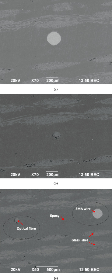
Figure 6. Scanning electron micrographs of (a) an SMA wire, (b) an optical fibre, and (c) a sample comprising an SMA wire, an optical fibre, and glass fibre reinforced epoxy.
Download figure:
Standard image High-resolution image2.5.2. Change of strains.
An SMA reinforced composite beam for longitudinal and transverse strain analyses is shown in figure 7. Figures 8(a)–(c) depict the reflected spectra of an FBG sensor extracted at room temperature, ΔT = 20 °C, and ΔT = 40 °C. Figures 8(d)–(f) show the reflected spectra of FBG 1, FBG 2, and FBG 3 obtained according to the change of temperature. The change of the strain shifts the Bragg wavelength by dilating or compressing the grating and changing the effective index of light in the optical fibre. In figure 8(e), it can be see that the reflected light intensity is increasing as the temperature rises. As the composite beam was deformed owing to distinct thermal expansion of the asymmetric lamination, this induced a pressure shift in the composite. The composite was bent due to the thermal expansion, and thus the intensity of the reflected light was changed.
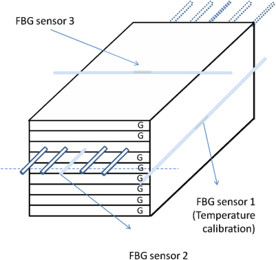
Figure 7. An experimental model of the composite for the longitudinal and transverse strain analyses. (G represents a layer of glass fabric.)
Download figure:
Standard image High-resolution image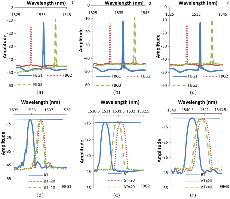
Figure 8. Reflected spectra of a grating extracted at (a) room temperature, (b) ΔT = 20 °C, and (c) ΔT = 40 °C. Reflected spectra of (d) FBG 1, (e) FBG 2, and (f) FBG 3 obtained according to the change of temperature.
Download figure:
Standard image High-resolution image2.5.3. Change of natural frequency.
The natural frequencies of the composite beams were measured with a Brüel & Kjær (B&K) accelerometer for calibration. The configuration of the B&K set-up included an accelerometer, charge amplifier, pulse front-end pulse dongle, and a computer for time signal and spectrum analysis. The frequency range of the set-up was 0–250 Hz.
A series of cantilever composite beams was impacted at a distance of approximately 15 mm from the clamped end. The frequency response functions of the clamped–free sample recorded by an accelerometer and FBG sensor are plotted in figure 9. Obviously, the natural frequencies obtained by the two different techniques are the same. The response peak is sharp, and it represents the natural frequency of 29.1 Hz for the composite at room temperature.
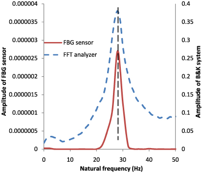
Figure 9. Natural frequencies obtained from the FBG sensor and a B&K system.
Download figure:
Standard image High-resolution imageFigure 10 shows the comparison of natural frequencies of the samples obtained from the FBG sensor at T < Mf and T > Af. The natural frequency of the cantilever composite beam is shifted from 29.1 Hz to 26.5 Hz when T > Af. During the experiment, it was found that the embedded SMA wires could regulate the natural frequency of the cantilever composite beams. The natural frequency of the cantilever composite beams depends on their dimension and constitution, the number of embedded SMA wires, and their transformation temperatures. However, the decrease of the natural frequency of the cantilever composite beams at T > Af was mainly due to the generation of an internal compressive stress by the mismatch of thermal expansions between the layers of glass fibre/epoxy, SMA wires, and optical fibre [18, 19]. Since the SMA wires and the optical fibre were not embedded in the neutral axis of the samples, the mismatch of the thermal expansion would therefore cause the bending of the sample accordingly upon heating.

Figure 10. Natural frequencies obtained from the FBG sensor at different temperatures.
Download figure:
Standard image High-resolution imageFigure 11 illustrates the vibration response of the cantilever composite beam subject to a localized impact loading. The damping properties of the cantilever composite beam at T < Mf and T > Af were analysed by an FFT analyser. In figure 11, it can be seen that, when the temperature increases, a reduction in the vibration amplitude occurs. Besides, the excitation is attenuated when the temperature increases. During the experiment, it was found that the damping properties and natural frequency of the cantilever composite beams could be modulated by increasing their temperature. This phenomenon was due to the change of the modulus, induced internal stress, and geometry of the cantilever composite beam.

Figure 11. Settling time of the composite at (a) T < Mf and (b) T > Af.
Download figure:
Standard image High-resolution image3. Theoretical analysis
3.1. The relationship of temperature and curvature of the unsymmetrical composite
Figure 12 shows the theoretical model of an unsymmetrical composite plate. For thin plates subjected to small deformations, the fundamental assumptions of Kirchhoff's hypothesis for plates are summarized as follows [20–23].
- (1)Deflections of the mid-surface are relatively small compared to the thickness of the composite plate, and the slope of the deflected plate is small.
- (2)The mid-plane is unstrained (ε = 0) when the plate is subjected to pure bending.
- (3)Plane sections that are initially normal to the mid-plane remain normal to the mid-plane after bending.
- (4)Normal out-of-plane strains are assumed to be zero when plate deflections are due to bending.
- (5)The condition σz = 0 is assumed to be valid.

Figure 12. Laminate stacking sequence nomenclature. (G represents a layer of glass fabric.)
Download figure:
Standard image High-resolution imageFor a thin laminated plate, in which the total laminate thickness is usually small compared to other plate dimensions, the plane stress relationship between Cartesian stresses and strains is
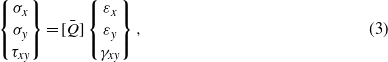
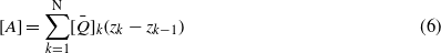
where ε, σ, τ, and γ are the strain, stress, shear stress, and shear strain, respectively. ![$[\bar {Q}]$](https://content.cld.iop.org/journals/0964-1726/22/12/125015/revision1/sms481972ieqn67.gif) is the in-plane elements of the stiffness matrix under plane stress condition. Each laminate through the thickness may have a different fibre orientation and consequently a different
is the in-plane elements of the stiffness matrix under plane stress condition. Each laminate through the thickness may have a different fibre orientation and consequently a different ![$[\bar {Q}],[\bar {Q}]_{\mathrm{GF}}$](https://content.cld.iop.org/journals/0964-1726/22/12/125015/revision1/sms481972ieqn68.gif) and
and ![$[\bar {Q}]_{\mathrm{SMA}}$](https://content.cld.iop.org/journals/0964-1726/22/12/125015/revision1/sms481972ieqn69.gif) . Under conditions of plane stress, the Cartesian components of the stress in the kth layer are
. Under conditions of plane stress, the Cartesian components of the stress in the kth layer are
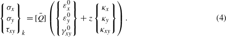
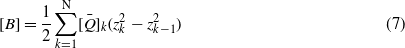
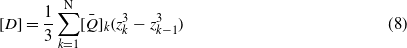
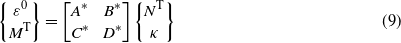
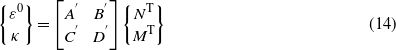
The above relationship is assumed to be valid for any layer of the laminate. However, the strain variation through a laminate is a function of both mid-surface strain and curvature, and it is continuous through the plate thickness, whereas the stress is not required to be continuous through the plate. The loads and the moments incorporated with thermal loads and thermal moments are expressed as
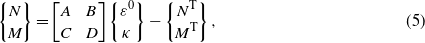
where N is the external load, M is the external moment, NT is the thermal load, and MT is the thermal moment.


When a two-phase model consisting of the austenite and martensite phases connected in series is applied, the elastic modulus of the SMA wire can be expressed as [24],

where ξ, EA, and EM are the volume fraction of martensite, and the elastic moduli of the parent phase and the martensite phase, respectively. If the volume fraction of martensite is assumed to be linearly proportional to the temperature, the longitudinal thermal expansion coefficient [20] can be obtained as
The transverse thermal expansion coefficient is given by [20],

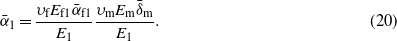
According to the data listed in table 1, the theoretical responses of strain and stress at different layers with the change of temperature are shown in figure 13. The neutral axis is shifted and no longer exists in the middle through the thickness of the model. The difference in strain between the bottom layer and the upper layer increases when the temperature increases. The composite plate was bent because of the distinct thermal expansion to cause strain decreasing in the upper layers but increasing in the lower layers. Figure 14 shows the curvature in the longitudinal and transverse directions as a result of the temperature change.
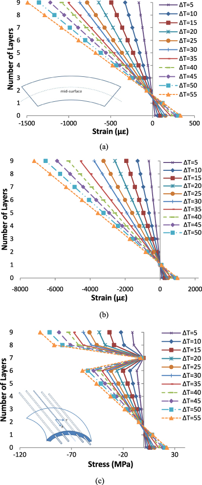
Figure 13. Responses of (a) a longitudinal strain, (b) a transverse strain, and (c) a stress in different layers with the change of temperature.
Download figure:
Standard image High-resolution image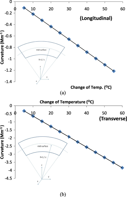
Figure 14. Generation of curvature in (a) a longitudinal direction and (b) a transverse direction as a result of the temperature change.
Download figure:
Standard image High-resolution imageIn figure 15, it is found that the strains in both cases decrease, but the stresses increase with increasing volume fraction of embedded SMA wires. The magnitude of stresses provides a general trend from positive to negative values when moving from the bottom layer to the upper layer. This is apparently attributed to the internal compressive stresses generated in the upper layer and the tensile stress in the bottom layer of the composite plate. Figure 16 shows that the curvature decreases with increasing volume fraction of SMA wires in the SMA reinforced composite, so the modulus of the composite increases.

Figure 15. Responses of (a) a strain and (b) a stress in different layers with different SMA volume fraction at ΔT > Af.
Download figure:
Standard image High-resolution image
Figure 16. Generation of curvature in (a) the longitudinal direction and (b) the transverse direction at ΔT > Af as a result of the different SMA volume fraction.
Download figure:
Standard image High-resolution image3.2. Damping ratio and damping coefficients of the composites
The damping ratio of the composite under the change of temperature can be evaluated by measuring the vibration amplitude in free vibration motion using the following damping equation [19]:
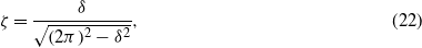
where  ; δ is the natural logarithm of the ratio of any two successive displacement amplitudes (u1 and u2) in the same direction. Figure 17 shows the damping ratio of the composite plate with the change of temperature. The internal damping of the material was changed according to the different temperatures. The maximum damping ratio is achieved when ΔT = 60 °C. The damping ratio tends to increase when the temperature and the curvature of the composite plate increase, as a result of the thermal expansion of the asymmetric laminate. Additionally, the energy dissipation arises from the internal friction at the interface of the stress-induced martensite. After ΔT > 60 °C, the damping ratio decreases, which is ascribed to the polymer softening as the glass transition temperature starts at around 65 ° C.

Figure 17. Damping ratio of the composite with the change of temperature.
Download figure:
Standard image High-resolution imageThe mathematical expression of the natural frequency of the composite is [22, 25]
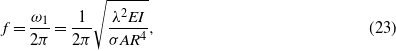
where E is the Young's modulus, I is the moment of inertia, A is the cross-sectional area, R is the radius of the curved composite beam, σ is the density of the composite, and λ is equal to 1.875 for the first mode of vibration. Figure 18 shows that the natural frequency increases with the temperature change from 0 to 15 ° C owing to the thermal expansion of the composite. When the temperature changes above 15 ° C, the decrease of the natural frequency can be mainly due to the reduction of the Young's modulus.

Figure 18. Natural frequency of the composite with the change of temperature.
Download figure:
Standard image High-resolution image
4. Conclusion
The mechanical and dynamic properties of a smart asymmetric composite made from glass fibre reinforced epoxy with embedded SMA wires and FBG sensor were studied in this paper. The experimental and theoretical analyses have shown that the composite underwent an abnormal shift of its neutral axis due to the formation of curvature upon heating up the SMA wires, and thus the composite. The natural frequency decreased as the temperature of the composite increased above the austenite finish temperature of the SMA wires. However, due to the change of the Young's modulus of the SMA wires, the damping ratio increases with the increase of temperature until reaching the glass transition temperature of the epoxy. The formation of curvature was due to the differential thermal coefficients of expansion of the different materials in the composite, which thus induced an internal stress to deform the composite. In this study, we proved that SMA wires and FBG sensors can be effectively used as intrinsic actuators and sensors for a smart composite system. However, the formation of internal stresses, which may alter the geometry of a composite structure, is an issue that has not be thoughtfully discussed elsewhere in the past. The use of embedded sensors can provide reliable information to the system in any case in which the deformation may reach a critical state.
Acknowledgment
This project was support by a University Research Grant (G-YK84) from The Hong Kong Polytechnic University.