


Abstract
Electrodes fabricated using commercially available silver nanowires (AgNWs) and single walled carbon nanotubes (SWCNTs) produced sheet resistances in the range 4–24 Ω □−1 with specular transparencies up to 82 %. Increasing the aqueous dispersibility of SWCNTs decreased the bundle size present in the film resulting in improved SWCNT surface dispersion in the films without compromising transparency or sheet resistance. In addition to providing conduction pathways between the AgNW network, the SWCNTs also provide structural support, creating stable self-supporting films. Entanglement of the AgNWs and SWCNTs was demonstrated to occur in solution prior to deposition by monitoring the transverse plasmon resonance mode of the AgNWs during processing. The interwoven AgNW/SWCNT structures show potential for use in optoelectronic applications as transparent electrodes and as an ITO replacement.
Export citation and abstract BibTeX RIS

Content from this work may be used under the terms of the Creative Commons Attribution-NonCommercial-ShareAlike 3.0 licence. Any further distribution of this work must maintain attribution to the author(s) and the title of the work, journal citation and DOI.
1. Introduction
Transparent electrodes are an important component in various optoelectronic devices, such as flat panel displays [1, 2], solar cells and light emitting diodes [3–5]. Indium tin oxide (ITO) has become the most prevalent transparent electrode material due to its low sheet resistivity (15–60 Ω □−1) and high optical transparency (>90%) [6]. Lifetime cost analysis of conventional organic photovoltaic (OPV) devices reveals that ITO is the most expensive component of current optoelectronic technologies, accounting for up to 87% of the total lifetime energy cost [7, 8]. The high cost associated with the use of ITO has encouraged research into alternative transparent electrode materials including carbon nanotubes (CNTs) [9–11], graphene [10–15], semi-conducting polymers [16–20], ultra-thin metal films [21, 22] and metal oxides [23, 24]. In recent years, silver nanowire (AgNW) electrodes have been gaining interest as a transparent conductive electrode material due to the ease of nanowire manufacture, scalable solution processability [25–28], high conductivity and mechanical ductility [29, 30]. Hu et al [31] have reported on the optimization of AgNW morphology for transparent electrode applications and conclude that long thin wires provide the highest conductivity and transparency. Furthermore, De et al [32] have optimized AgNWs surface loadings to 47 mg m−2, achieving a sheet resistance of 13 Ω □−1 at 85% transmittance.
The inter-nanowire junction resistance has been found to be a significant limitation to the overall conductivity and approaches such as coating AgNWs with gold via a simple galvanic process reduced the junction resistance dramatically from >1 GΩ to 450 Ω [31]. Garnett et al [33] have fused AgNW junctions using a self-limiting light-induced plasmonic welding technique, reducing the junction resistance by a factor of over 1000. Mechanically pressing AgNW films has also been found to increase the electrode conductivity by increasing the contact area between the AgNWs [31, 34], while the fabrication of AgNW composites with conductive interconnecting materials such as metal oxide nanoparticles [35] and single walled carbon nanotubes (SWCNTs) has also proved effective [36].
Diffusion of free carriers in organic photovoltaic electrodes relies on a continuous conduction pathway to ensure efficient extraction of free charges generated within the active layer, however, AgNW-only films with high optical transmission typically consist of a sparse nanowire network with holes of up to 1 μm [37]. Therefore, a second interpenetrating network or matrix is required to efficiently collect free charges within holes of the AgNW network. Recently, Tokuno et al [36] fabricated AgNW/SWCNT interwoven films via a drop coating method from an ethanol dispersion resulting in a decreased sheet resistivity, from 132 Ω □−1 for AgNW-only films to 29 Ω □−1 after the addition of SWCNTs at a weight fraction of 6 wt% [36]. However, as the ratio of SWCNTS was increased to 50 wt% the sheet resistivity increased significantly to 1.1 × 10⁶ Ω □−1 which is far above an operational sheet resistivity for optoelectronic devices [36].
This paper reports on a solution processing approach to the fabrication of AgNW/SWCNT transparent electrodes which can achieve excellent optical and electrical properties up to 50 wt% SWCNT content.
The morphology of the AgNW and AgNW/SWCNT films were determined using atomic force microscopy (AFM) and found to be an interwoven network of AgNWs and SWCNTs. UV–visible AgNW transverse plasmon resonance was used to determine at which point AgNW and SWCNT entanglement occurred.
2. Experimental
2.1. Materials
AgNWs were purchased from Seashell Technologies (San Diego, USA) which were supplied as a suspension in isopropyl alcohol (IPA). An aliquot of the AgNW suspension was diluted to 0.1 mg ml−1 with IPA and stored until use. Carboxylate functionalized (P3 type) SWCNTs with a carbonaceous purity of >90% were purchased from Carbon Solutions (California, USA). A sample of the SWCNTs was suspended in water via probe sonication (Sonics VibracellTM) at 40% amplitude for 2 min before being diluted to a concentration of 0.25 mg ml−1 with deionized water. To reduce the bundle size of the functionalized SWCNTs the carboxylate functionalized SWCNTs (50 mg) were refluxed further in 3 M HNO3 (50 ml) for 12 h which has been shown to increase the dispersibility of SWCNTs in water [38].
2.2. Methods
AgNW/SWCNT films were prepared via vacuum filtration through mixed cellulose ester membranes (MF-Millipore Membrane, USA, mixed cellulose esters, hydrophilic, 0.4 μm, 47 mm). Various volumes of the prepared AgNW (0.1 mg ml−1) and SWCNT (0.25 mg ml−1) solutions were added to 300 ml of deionized (DI) water so that surface loadings of 198 and 98 mg m−2 could be achieved in the final electrode (64 mm2). Electrode patterning was achieved by placing a smaller pore size mixed cellulose ester template (MF-Millipore Membrane, mixed cellulose esters, hydrophilic, 0.025 μm, 47 mm) under the 0.4 μm membrane during filtration (figure 1(a)). After filtration the patterned electrodes were then placed on pre-cleaned glass substrates (sonicated in acetone and isopropanol for 15 min) (figure 1(b)). The glass and patterned electrodes were then subjected to heating at 80 °C under a pressure of 0.16 kg cm−2 in a vacuum oven (Memmert, Germany) for 30 min. The mixed cellulose ester filter paper was subsequently removed by dissolution in acetone for 30 min leaving behind the patterned AgNW/SWCNT films on the surface of the glass substrate (figure 1(c)).
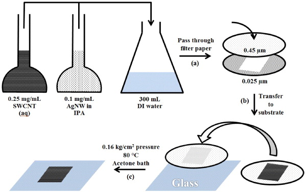
Figure 1. Schematic showing transparent electrode fabrication through (a) membrane filtering, (b) glass transfer, (c) heating under pressure followed by acetone dissolution. DI refers to deionized water.
Download figure:
Standard image High-resolution imageStructural integrity of the patterned electrodes was tested by floating the AgNW/SWCNT films on the surface of acetone. Immediately following vacuum filtration the patterned cellulose ester membrane substrates (64 mm2) with the AgNW and AgNW/SWCNT films were lowered into an acetone bath via two metal wire supports to avoid complete film submersion. After a certain period (0–10 s) the cellulose ester membrane was dissolved by the acetone leaving behind a self-supporting film of either AgNWs or AgNW/SWCNTs floating on the acetone surface. The films were monitored for AgNW re-suspension, an indicator of the integrity of the film.
Sheet resistance measurements were performed using a four point probe (KeithLink Technology Co, Ltd, New Taipei City, Taiwan). The values reported were an average of ten measurements on two separate 64 mm2 samples.
Specular transmission was measured by using a Varian-Cary 50 Bio UV–visible spectrophotometer. The specular transmission of each film was measured and is reported as the average transmission over a wavelength range of 800–400 nm. Solution UV–visible studies were performed on the same instrument. Solution phase interactions between the SWCNTs and AgNWs were monitored by isolating the AgNW transverse plasmon mode in the presence of increasing SWCNT concentration. 0.5 ml of a 0.1 mg ml−1 AgNW IPA solution was placed in 5 ml of deionized water in a quartz cuvette, the spectra was recorded over 500–325 nm. SWCNTs were subsequently added to the AgNW suspension at 10, 20, 33 and 50 wt% and the spectra re-collected. The AgNW spectra were isolated by background subtracting the SWCNT contribution from the spectrum.
Scanning electron microscopy (SEM) images were acquired using a Philips XL30 field emission scanning electron microscope (FE-SEM) (FEI company, Oregon, USA) working at an accelerating voltage of 5.0 kV and a distance of 10 mm.
Transmission electron microscopy (TEM) images were acquired on a Philips CM200 transmission electron microscope (FEI company, Oregon, USA) at an accelerating voltage of 200 kV. SWCNT dispersions were drop cast onto amorphous carbon backed copper grids and allowed to dry before imaging.
All atomic force microscope (AFM) measurements were acquired using a Bruker Multimode AFM with Nanoscope V controller. NSC15 Mikromasch Silicon tapping mode probes with a nominal spring constant of 40 N m−1, resonant frequency of 325 kHz and tip radius equal to 10 nm were used. AFM images were acquired in tapping mode with all parameters including set-point, scan rate and feedback gains adjusted to optimize image quality and minimize imaging force.
3. Results and discussion
The nanomaterials were characterized to confirm their aspect ratios. Figure 2(a) shows that the lengths of the as-purchased AgNWs are in the order of 5–50 μm with a diameter of approximately 100–200 nm. Figure 2(b) shows the morphology of the drop cast SWCNTs and the insert reveals that the SWCNT bundle diameter is 5–15 nm, considerably less than the hundreds of nanometre bundle size observed by Tokuno et al [36].
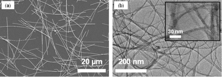
Figure 2. (a) FE-SEM image of AgNWs and (b) TEM image of SWCNTs. The inset is a higher magnification TEM image showing the diameter of SWCNT bundles.
Download figure:
Standard image High-resolution imageTypically, individual SWCNTs are approximately 2 nm in diameter, however SWCNT bundling occurs due to van der Waals interactions between the carbon nanotube side walls [39].
Figures 3(a) and (b) show the average specular transparency (closed squares) and variation of sheet resistance (closed triangles) of AgNW/SWCNT electrodes (64 mm2) loaded on the electrode surface at 195 and 98 mg m−2, respectively. It can be seen in figure 3(a) (195 mg m−2 AgNW surface loading) that as the weight fraction of SWCNTs is increased the average specular transparency decreases (figure 3(a), closed squares). Since the surface loading of AgNWs remained constant (at 195 mg m−2) the observed decrease in average specular transparency is due to increased concentration of SWCNTs, which is an absorptive species [40]. Interestingly, as the SWCNT weight fraction is increased it is found that the measured sheet resistance reaches a minimum at a SWCNT loading of 20 wt% (figure 3(a) closed triangles). The decrease in sheet resistance up to a weight fraction of 20 wt% can be explained due the presence of bridging SWCNTs between adjacent AgNWs which act as a conductive interconnecting material.

Figure 3. Variation of sheet resistance and transparency of AgNW/SWCNT 64 mm2 electrodes as a function of weight fraction of SWCNTs at two AgNW surface concentrations (a) 195 mg m−2 and (b) 98 mg m−2. Closed squares refer to transparency and closed triangles refer to the sheet resistance. The effect of mild acid reflux of SWCNT on sheet resistance (open triangle) and transparency (open square) is also shown at 50 wt% (b). Error bars represent the standard deviation of ten measurements.
Download figure:
Standard image High-resolution imageIt is important to note that only the specular transmittance is reported here in order to provide a direct comparison to that reported by Tokuno et al [36]. In many applications for ITO replacement materials, functional layers are adjacent to the electrode and some diffuse transmittance (forward scattering) is not an issue and may be a benefit to overall device performance. The diffuse scattering of the 98 mg m−2 AgNW sample was found to be 5% using an integrating sphere, providing a total transmittance of 89%. Reflections arising from refractive index mismatches provide another significant contribution to the reduction in the total light transmitted.
For films with a AgNW surface loading of 98 mg m−2 (figure 3(b)) the average spectral transmission and sheet resistance was shown to remain similar to that of the AgNW only film, remaining at approximately 80–85% and 10 Ω □−1, respectively up to 33%. The 50% SWCNT weight fraction sample had an increased sheet resistance of 24 Ω □−1 (figure 3(b), closed triangles) while the average specular transmission is reduced to 60% (figure 3(b), closed squares). These results are contradictory to those reported by Tokuno et al [36], who found that a SWCNT weight fraction of 6 wt% exhibited a sheet resistance of 29.2 Ω □−1. However, at weight fractions of SWCNTs above 6 wt% the sheet resistance increased dramatically, up to 1.1 × 10⁶ Ω □−1, for SWCNT weight fractions of 50 wt% [36]. The improvement, shown in figures 3(a) and (b), over that reported by Tokuno et al is thought to be due to the morphology of the nanomaterials used in the film production. In particular, the purchased SWCNTs were carboxylate functionalized which enhanced the dispersibility in water, reducing bundle size, and therefore increased the number of possible connections between the AgNWs.
To explore the influence of SWCNT bundling, a 50 wt% AgNW/SWCNT composite at a surface loading of 98 mg m−2 AgNW was fabricated with SWCNTs which had undergone refluxing in 3 M HNO3 for 12 h. Figure 3(b) shows the sheet resistance of a 50 wt% SWCNT film fabricated with refluxed SWCNTs showing a decrease from 24 to 11 Ω □−1 and an increased specular transmittance from 54 to 76%, following the trends established for lower weight fraction SWCNT films. Interestingly, the sheet resistance of lower weight fraction AgNW/SWCNT films remained unchanged within experimental error when fabricated using SWCNTs which had been refluxed in 3 M HNO3. It is speculated that reduction of the sheet resistance arises from a reduction in SWCNT bundle size in the interwoven film, resulting in closer contact of the AgNWs. Moreover, in lower weight fraction SWCNTs films, the SWCNT surface concentrations are too low to affect the AgNW contacts. The increased average specular transparency may be explained by a more uniform surface coverage of SWCNTs at the same SWCNT surface loading. Importantly, this observation shows that increasing the dispersibility of the SWCNTs can provide increased conductivity whilst maintaining optical transparency in high weight fraction composites.
Figures 4(a)–(f) show AFM images of films containing AgNWs only, SWCNT films at 10, 20, 33 50 and 50 wt% with 3 M acid refluxed SWCNTs respectively. Height profiles along the AgNWs, indicated in each AFM image as a black line, are shown in figure 4(g, 1–5). It is clear from figure 4 that after the addition of SWCNTs (10–50 wt%) to the AgNWs, an interpenetrating woven network is created (figures 4(b)–(e)). Height data along the AgNWs (figure 4(g, 1–5)) shows that as the fraction of SWCNTs increases the AgNWs surface becomes increasingly rough due to the association of the SWCNTs with the AgNWs. At a surface loading of 50 wt% the AgNWs become completely encased in the SWCNT layer and bundles of SWCNTs are present at the surface (figures 4(e) and (g, 5)). It may be concluded that at a weight fraction of 50 wt% the SWCNTs are present in a sufficient concentration to inhibit direct contact of overlapping AgNWs, a possible explanation for the observed increase in the sheet resistance of 50 wt% films (figures 3(a) and (b), closed triangles). The height amplitude variation along the AgNW (figure 4 (g, 6) for the refluxed SWCNTs (figure 4(f)) is less than that of non-treated SWCNTS (Figure 4 (g, 5)), which is presumably due to the increased dispersibility of the SWCNTs after treatment with 3 M HNO3. The continuous networks of SWCNTs between the AgNW, observed at 33 and 50 wt% (figures 4(d) and (e)) are likely to be advantageous for charge collecting electrodes since the generated charge carriers have less distance to travel before being collected by the SWCNT or AgNW electrode matrix in an effect analogous to that observed for in charge collecting grid electrodes with various spacing [37].

Figure 4. AFM height images of AgNW and SWCNT films on a glass substrate at (a) 0, (b) 10, (c) 20, (d) 33 and (e) 50 wt% SWCNT fraction without further treatment, while (f) is for a 50 wt% SWCNTs film after refluxing in 3 M HNO3. The white scale bars correspond to a distance of 2 μm. Panel (g) shows the height data long AgNWs indicated in each AFM height image as a black line. The black scale bars in panel (g) correspond to a height of 40 nm.
Download figure:
Standard image High-resolution imageThe structural integrity provided by the interwoven nature of the film was investigated by observing the stability of a self-supported film floating on acetone. Figure 5(a) shows that upon dissolution of the cellulose ester membrane, the AgNW only film has minimal integrity and tears immediately before disintegrating entirely within 240 s due to the lack of any significant attractive force between the AgNWs. As the SWCNT weight fraction was increased, the films remain increasingly stable after dissolution of the cellulose ester membrane (figures 5(b)–(d)). At a SWCNT weight fraction of 20 wt% (figure 5(b)) disintegration around the edges of the film are visible after 60 s of cellulose membrane dissolution, however, for the films fabricated with weight fractions of 33 and 50 wt% SWCNTs (figures 5(c) and (d)) there was no observable degradation of the film, other than the original damage that occurred during fabrication. Furthermore, the films remained structurally stable for more than 24 h.
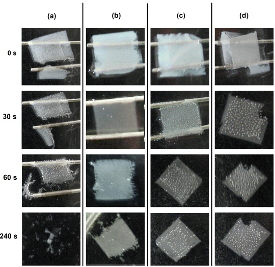
Figure 5. Colour photographs of the (a) AgNW only films and AgNW/SWCNT films at a SWCNT weight fraction of (b) 20, (c) 33 and (d) 50 wt% during structural integrity testing floating on top of an acetone bath. The area of each film is 64 mm2.
Download figure:
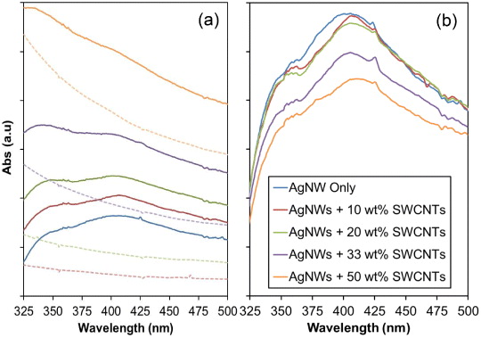
Standard image High-resolution imageTo better understand the stage of processing at which the SWCNTs entangle with the AgNWs, the solution transverse plasmon resonance of AgNWs was examined by UV–visible spectroscopy. If SWNTs were to wrap around the AgNWs, the resulting interaction with nanotubes would reduce the density of electrons that support plasmon propagation in the AgNWs, therefore, the absorbance due to surface plasmon resonance will be affected. Figure 6(a) shows the UV–visible absorption spectra for films of AgNWs only, SWCNT films at 10, 20, 33 and 50 wt% and figure 6(b) shows the true intensity absorption spectra for films of AgNWs only, SWCNT films at 10, 20, 33 and 50 wt% with the SWCNT absorption contribution background subtracted, isolating the AgNW absorption for each solution. The background data for each sample is shown in figure 6(a) as dashed lines in corresponding colours.
Figure 6. UV–visible spectrophotometer data in the AgNW plasmonic absorption wavelength range. Solid lines show AgNW only and SWCNT suspensions at 10, 20, 33 and 50 wt% (a), dashed lines show the SWCNT background data which was subtracted for each suspension to obtain data in (b). (b) AgNW only films and SWCNTs with the SWCNT contribution background subtracted showing reduction in AgNW transverse plasmon mode (solid line minus corresponding dashed line from (a)).
Download figure:
Standard image High-resolution image
Figure 6(b) reveals two AgNW absorptions at approximately 350 and 400 nm. The absorption at approximately 350 nm can be assigned to bulk silver and the broad absorption band at 400 nm is that of the transverse plasmon mode typically observed for cylindrical nanowires [41, 42]. The longitudinal plasmon absorption is not observed due to the high aspect ratio of the AgNWs. The broad absorption profile at 400 nm is due to the large range of nanowire widths (approximately 100–200 nm, figure 2(a)). Figure 6(b) shows a decrease in the transverse plasmon resonance intensity at 400 nm with increasing SWCNT loading. This quenching may be explained as the interaction of SWCNTs with the surface of the AgNW reducing the density of generated plasmons. As expected, this effect is more pronounced for higher weight fraction SWCNT composites (33 and 50 wt%). Moreover, the shape of the transverse plasmon mode absorption in figure 6(b) changes upon the addition of SWCNTs, which may indicate whether there are significant electrostatic or side wall interactions between the SWCNTs and AgNWs.
4. Conclusions
AgNW/SWCNT films with electrical/transmission properties over a superior compositional range than previously reported have been fabricated via solution-based processing, with sheet resistances between 4–24 Ω □−1 and specular transparencies up to 82%. It was shown that the SWCNTs wrap around the AgNWs resulting in a conductive interconnect as well as a mechanical support providing structural integrity in free floating films. In high weight fraction SWCNT films, large bundles of SWCNTs prevent close contact of AgNW. Critically, the sheet resistance and optical transparency at higher SWCNT loadings was demonstrated to be dependent on the dispersibility of the SWCNT in solution prior to deposition, which reduced bundle size in the final composite allowing close contact of AgNWs. Quenching of the AgNW transverse plasmon mode in UV–visible spectroscopy provided evidence for solution-based interaction of the SWCNTs and AgNWs, indicating the association between these structures prior to deposition as a film and opening solution processing opportunities. The morphology of high weight fraction SWCNT composite films are expected to yield improved charge collecting efficiency due to interwoven nature of the SWCNTs and AgNW network and the increased secondary conduction pathways. The interwoven films presented have significant promise for use in optoelectronic applications as the transparent electrodes and as an ITO replacement.
Acknowledgments
This work was supported by the CSIRO Future Manufacturing Flagship: Flexible Transparent Electrodes for Plastic Electronics Cluster which includes The University of Queensland, University of Technology, Sydney and Flinders University. We are grateful to the Australian National Fabrication Facility (ANFF) for access to the electron microscope facilities.