


Abstract
Continuous monitoring of a cloud of antiprotons stored in a Penning trap for 405 days enables us to set an improved limit on the directly measured antiproton lifetime. From our measurements we extract a storage time of  equivalent antiproton-seconds, resulting in a lower lifetime limit of
  with a confidence level of
  . This result improves the limit on charge-parity-time violation in antiproton decays based on direct observation by a factor of 7.
Export citation and abstract BibTeX RIS

Original content from this work may be used under the terms of the Creative Commons Attribution 3.0 licence. Any further distribution of this work must maintain attribution to the author(s) and the title of the work, journal citation and DOI.
1. Introduction
As a consequence of the charge-parity-time reversal symmetry [1], it is required that the proton (p) and the antiproton ( ) lifetimes,
  and
and  , are identical. Any asymmetry in
  and
and  would constitute a challenge to the Standard Model and contribute to our understanding of the universal baryon asymmetry. In the context of searches for baryon-number violation [2], the lifetime
  of the proton has been one of the subjects of investigation. In direct measurements stringent limits up to
  a [3] have been derived, while in specific decay channels even constraints up to
  a [4] were achieved. However, experimental limits on the antiproton lifetime
  are much lower. For example, model-dependent estimates on the antiproton lifetime have been derived from comparisons of the measured cosmic-ray
  flux, with models describing the production and propagation of antiprotons in the interstellar medium [5]. From these considerations the limit
  a has been reported. Other
  lifetime constraints have been derived from Fermilab's storage-ring based APEX experiment [6], which placed limits on 13 charged leptonic antiproton decay modes. Depending on the considered decay channel, lifetimes in the bounds of
  a to
a to  are extracted [6]. However, some decay modes favoured by supersymmetric Grand Unified Theories [7, 8], such as
  have so far only been constrained experimentally by Penning-trap experiments which reported
  [9] and
  [10], respectively.
Here we report on a 7-fold improved constraint on the directly measured antiproton lifetime obtained by continuous counting of antiprotons stored in the cryogenic Penning-trap system of CERN's BASE collaboration. In our 2015/2016 experimental run a cloud of antiprotons was trapped for 405 days, to our knowledge antimatter trapping for such a long time period has never been reported before. Within the entire observation time we have not observed any antiproton decay or annihilation with residual gas. Based on the available data samples we extract  at
at  confidence level. In addition, we discuss the feasibility of extending this demonstration to a dedicated trap-based antiproton lifetime measurement.
2. Methods
2.1. Apparatus
The BASE apparatus [11] is located at CERN's Antiproton Decelerator (AD) facility in Geneva, Switzerland, and consists of four stacked Penning traps. A Penning trap is formed by the superposition of a homogeneous magnetic field in axial direction and a quadrupolar electrostatic field by applying appropriate voltages to trap electrodes of carefully chosen geometry [12]. The trajectories of trapped particles are composed of three independent harmonic oscillator modes [13]: the axial oscillation along the magnetic field lines  , and the two radial oscillation modes
  .
.  is the free cyclotron frequency with the static magnetic field
  and the antiproton charge-to-mass ratio
  . In the traps of our apparatus, the axial mode has a frequency in the order of
  kHz, the modified cyclotron mode
  MHz, and the magnetron mode
  kHz, respectively. The traps are placed inside an indium-sealed copper cylinder with a volume of 1.2 l and cooled to about 6.2 K. Cryo-pumping of the hermetically-sealed trap cylinder is the key to provide the ultra-low pressure and consequently the long antiproton storage time.
2.2. Particle trapping, detection and manipulation techniques
The trap most relevant to the experiments described here is the reservoir trap (RT) [10, 11] shown in figure 1.
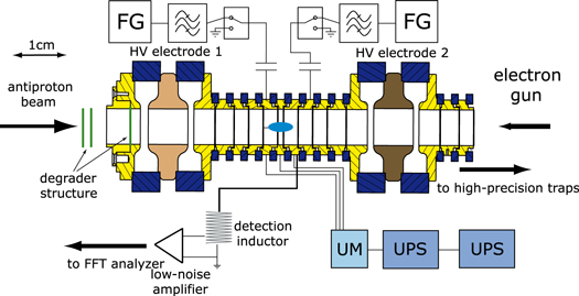
Figure 1. The reservoir trap (RT) contains a cloud of antiprotons. Its central electrodes are biased by a highly stable DC source (UM), which is secured against power outages by uninterruptable power supplies (UPS). The other electrodes are grounded, except for the transport procedures during the particle extraction. The particle signal is detected with a sensitive image-current detection system consisting of a superconducting tuned circuit and a cryogenic low-noise amplifier. Furthermore, radiofrequency drives for particle manipulation are connected to the trap electrodes. These drives are generated by frequency generators (FG) and are bandpass-filtered and connected to ground whenever possible to prevent parasitic excitation of the particles.
Download figure:
Standard image High-resolution imageThe trap electrodes are biased by a high-precision voltage source [14], which is protected against power cuts of up to 20 hours by uninterruptable power supplies. Radiofrequency drive lines are connected to the electrodes to manipulate the trapped particles. To detect the particles, a highly-sensitive superconducting image-current detection system [15] is connected to an electrode next to the central ring electrode of the trap. This device is used for detection and resistive cooling [16] and allows for the continuous monitoring and counting of trapped antiprotons. It has a resonance frequency of  kHz, an inductance
  mH and a quality factor
  , resulting in an effective parallel resistance of
  MΩ. High-voltage electrodes for antiproton catching are placed upstream and downstream of the central trap electrodes. A degrader structure to slow down the 5.3 MeV antiprotons provided by the AD is located upstream of the trap. Downstream, a field-emission electron source is installed, which provides electrons for sympathetic cooling of antiprotons [17].
To catch a pulse of antiprotons, we first load about 104 electrons into the trap and subsequently apply  kV to the high-voltage electrodes. An adequately timed high-voltage pulse, which is applied to the upstream catching electrode and is triggered by the AD antiproton ejection, traps a 10−4 fraction of the
  incident antiprotons. After about 10 s of sympathetic cooling, the electrons are removed by a strong resonant axial radiofrequency drive. Subsequently, potentially co-trapped negatively-charged ions are removed by a noise drive that excites all ions with mass-to-charge-ratio
  u/e, u and e being the atomic mass unit and the elementary charge, respectively. The axial oscillation frequency of negatively-charged hydrogen ions (m/q ≈ 1 u/e) is about 400 Hz lower than the frequency of the antiprotons, which makes their decisive identification possible. To remove them, we do not directly excite their axial oscillation because the excitation could act on the antiprotons as well. Instead, we excite the modified cyclotron mode
  of the hydrogen ions, which is separated by about 30 kHz from the antiprotons' modified cyclotron mode, and lower the trapping potential to a few
  mV afterwards. In such shallow potentials, anharmonic coupling transfers radial to axial energy and the excited ions escape from the trap along the magnetic field lines. In a next step, the antiprotons are cooled resistively by adjusting the trap voltage V0 such that
  is tuned to the resonance frequency
  of the superconducting detector. Finally, sideband coupling is applied to cool the radial modes of the antiprotons [18]. By following this procedure we typically prepare about 100 cold antiprotons per AD extraction.
2.3. Particle–detector interaction
Once the axial energy  of the trapped antiprotons is cooled to thermal equilibrium with the detector,
  , where
  is the Boltzmann constant and Tz is the temperature of the detection system, the equivalent particle impedance shorts the thermal noise
  [19] produced by the real part
  of the detector's impedance. In this case a notch occurs in the frequency spectrum of un [16]. The fast Fourier transform (FFT) of the time transient of such an axial frequency signal is shown in figure 2. Due to incoherent averaging of the thermally uncorrelated trapped particles, the width
  of the observed frequency dip is proportional to the number N of trapped antiprotons
  . Here,
  ms is the cooling time, and
  mm is a trap-specific length. From fits to the measured spectra we extract
  . For an FFT averaging time t, the rms scatter of
  extracted by our fitting routine is a linear function
  . Here,
  is the single-particle dip width, and the parameter α is a function of the parameters of the detector, such as quality factor and signal-to-noise ratio, stability of the power supply biasing the trap electrodes, settings of the FFT analyser and also of FFT overlapping and weighting algorithms in the fitting routine. Consequently, the time required to achieve single-particle resolution at 68% confidence level is
  . For the current parameters of our experiment,
  .
.
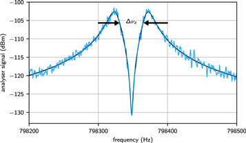
Figure 2. Fast-Fourier transform of a time transient signal of the axial detection system with a cloud of 18 antiprotons tuned to the centre of the detector. The width of the short in the noise resonance is proportional to the number of trapped particles. Measured data is shown in blue, the black curve represents the fit to the data. For more information, see text.
Download figure:
Standard image High-resolution image2.4. Calibration of the particle number
To derive limits on the lifetime of the antiproton from such measurements, the RT time transients un are recorded continuously, and a frequency spectrum is computed typically every 60 s. When the main experiment requires particles, we extract a single antiproton from the RT and shuttle it to the adjacent precision trap (PT). Consequently, the width of the frequency dip in the RT is reduced and the extracted particle appears on the detector spectrum of the PT. Figure 3(a) shows results of one of these extraction sequences. Such measurements allow us to perform a careful calibration of the width  of the axial frequency dip in the RT as function of the number N of trapped antiprotons. Figure 3(b) shows results of this calibration, which was obtained by sequentially reducing the number of trapped antiprotons from the RT and extracting
  . A straight-line fit to the data yields the calibration
  with
with  .
.
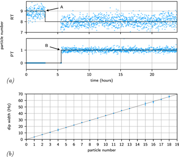
Figure 3. (a) Particle numbers obtained from the measured dip widths as a function of time in the reservoir trap (RT) and the precision trap (PT). Extraction removes a particle from the RT (A). The particle is then transported to the PT where it appears on the detector's noise spectrum (B). (b) Measured dip widths as function of particle number. By fitting a straight line to integer numbers as function of the dip widths yields the calibration factor to determine the number of particles.
Download figure:
Standard image High-resolution image3. Results
The data set which contributes most to the antiproton lifetime limit derived here is shown in figure 4. It is a consistent sample of continuously-recorded axial frequency dip widths  , with particles which were initially trapped in November 2015. Continuous data logging started in January 2016 with 18 trapped particles and was concluded in December 2016 with a single particle, collecting about
  data points. Within the entire data collection period we have not observed any antiproton decay or annihilation due to interaction with residual gas. All the observed steps
  can be unambiguously correlated to particle extraction from the reservoir. Extractions are caused by particle losses in the precision Penning-trap cycle of the experiment, which are either related to experiment operation or to tracked errors in the experiment control. Periods of high particle consumption (see figure 4) are linked with the development of experiment routines, whereas continuous measurement periods, such as [20], have a low consumption rate.

Figure 4. Determination of the exposure in the RT. The filtered dip width data as function of the date is shown as blue dots, the corresponding particle number as black line. Each time when a particle is extracted towards the precision traps, the particle number decreases by one. Integrating the time including the corresponding particle numbers yields the exposure, shown as red curve.
Download figure:
Standard image High-resolution image
To obtain the equivalent single-particle exposure time from this dataset, we integrate  , the result being represented by the red line in figure 4. The integrated single-particle equivalent exposure extracted from this sample is
  a. In addition we keep a record on the particles in the other traps, from which we obtain an equivalent exposure of
  a. We add to these two main data sets results from experiments carried out in the 2015 antiproton run, which were recorded before 01/01/2016,
  a, as well as the previously published storage time from our 2014 run [10], with
  a. By summing up these results we obtain the total integrated single-particle equivalent exposure of
  a, as summarised in table 1.
Table 1. List of individual data sets which contribute to the derived antiproton lifetime limit, see text for details.
| Specific dataset | Exposure time (years) |
|---|---|
| RT | 5.77 |
| Precision traps | 1.72 |
| RT systematics | 2.61 |
| 2014 run | 1.56 |
| Sum | 11.66 |
By modelling the decay as a Poisson process  with
with  and
and  events, we extract the lower lifetime limit for a chosen confidence level CL by solving following equation for
  :
:
Based on this approach and for an equivalent one-particle exposure of  a, we extract a lower limit on the directly measured antiproton lifetime of
  at
at  confidence level and
  at
at  confidence level. Based on this result we can derive upper limits of the partial pressures of hydrogen
  and helium
  in the cryopumped trap can. We follow the approach of [21] and obtain
  mbar and
  mbar at 68% confidence level.
4. Discussion
This demonstration experiment to derive antiproton lifetime limits based on the continuous, non-destructive direct observation of individual trapped antiprotons was carried out in the BASE Penning traps. The number of 18 trapped particles which were initially stored was deemed to be sufficient to reach the goal of operating BASE experiments independently of the accelerator for a shutdown period of six months—eventually experiment operation of even more than 405 days was demonstrated successfully. The number of particles was sequentially reduced to supply the adjacent precision Penning traps. The derived value for  is limited by the small number of initially trapped particles and the particle consumption by the main experiment. Our measurement technique is an extension of one described in [10], with sophisticated data accumulation and analysis, and significantly different from the lifetime measurement described in [9], where the number of trapped antiprotons was not determined on the single-particle level, but measured destructively by their annihilation signal on a scintillator. However, both measurements are sensitive to particle disappearance decay channels.
With an explicitly dedicated experiment, a much more stringent limit on directly measured antiproton lifetime could be derived. Here, a second trap with a cloud of continuously-monitored highly-charged ions, located in the same volume as the antiproton trap, could be used as highly-sensitive in-situ pressure gauge. This helps to disentangle whether potentially observed antiproton losses are related to intrinsic decays or caused by annihilations with background gas. For highly-charged ions of charge Z the sensitivity to background gas is enhanced by Z, compared to antiprotons. Loading and charge breeding of e.g.  in a closed cryogenic trap can has been demonstrated [22], and the implementation of such a highly-charged ion co-trap is feasible [20]. In the ideal case, and with the apparatus used here, in which we operate experiments at inter-particle correlation lengths lc above the Debye length
  , for example, about 120 days of data taking would be required to achieve with a cloud of 10 000 trapped particles the required single particle resolution at
  confidence level. Given the characterised stability of our experiment and the fact that 405 days of continuous antiproton storage has been demonstrated here, we consider it feasible to reach trap-based lifetime limits of order
  –
– a. Larger numbers of trapped antiprotons can be achieved by stacking, which has been demonstrated by other AD collaborations. Using optimised degrader structures, values of orders up to several 105 are reported [23, 24]. Further extension to experiments operating in the plasma range
  might be possible, however a detailed feasibility discussion of this case requires additional experimental studies.
Acknowledgments
We acknowledge support by the Antiproton Decelerator group, CERN's cryolab team, and all other CERN groups providing support to Antiproton Decelerator experiments. We acknowledge financial support by the RIKEN Initiative Research Unit Program, RIKEN President Funding, RIKEN Pioneering Project Funding, RIKEN FPR Funding, the RIKEN JRA Program, the Grant-in-Aid for Specially Promoted Research (grant number 24000008) of MEXT, the Max-Planck Society, the EU (ERC advanced grant number 290870-MEFUCO), the Helmholtz-Gemeinschaft, and the CERN Fellowship program.